In 1882, the Russian scientist N. N. Benardos was the first in the world to connect metal parts using electric arc welding. In his installation, he used non-consumable carbon electrodes and separate supply of filler material and flux. Based on this method, Benardos also developed gas shielded welding and electric arc cutting. Six years later, welding technology was invented using consumable electrodes, which over time almost completely replaced coal electrodes. Currently, the latter are limited in their application to three main areas: removal of excess metal, arc cutting and welding of individual materials.
On the Russian Internet, in articles about welding technologies you can often find such a name as “graphite electrode”. Without going into detail about the reasons for this phenomenon, it should be noted that GOST does not provide for the production of welding electrodes from graphite. The state standard regulates only graphite spectral electrodes used for laboratory research. Manufacturers can produce carbon and graphite rods as shaped products according to TU 1915-086–00200851, but in this way, as a rule, they produce only thick electrodes for cutting scrap and processing castings.
In addition, metallurgical enterprises that use graphite electrodes for electric arc furnaces independently produce non-standard welding electrodes from the fragments of these large-sized products, which, in fact, can also be called graphite.
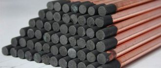
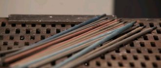
Figure 1 - Graphite electrode
Purpose of carbon electrodes
Carbon electrodes are mainly used for sealing defects in forgings, castings and rolled metal products, removing excess metal from the surface of welds and massive workpieces, as well as for welding certain types of metals and their alloys. They are usually used for such types of work as:
- elimination of tides, sinks and other defects;
- planing the roots of welding seams;
- cutting off tacks and old welding;
- burning holes;
- cutting off rivets;
- welding metal workpieces with thin edges;
- welding of non-ferrous metals;
- welding connection of cores and busbars during electrical work.
When cutting off excess metal, the gouging method is usually used - blowing boiling metal out of the weld pool with a narrowly directed stream of compressed air (see below). In this way, cavities in cast billets and forgings are cleaned, and the defective layer of metal is removed from welds.
The use of these products for welding non-ferrous metals is mainly limited to cast iron, copper and its alloys (see table).
| № | Part material | Filler rod material | Flux | Add. conditions |
| 1 | Copper | Tin-phosphor bronze, silicon brass and copper (M1 or MCr1). | Borax with the addition of charcoal, sodium hydrogen phosphate and silicic acid. | — |
| 2 | Bronze | Same as the main product. | For tin bronzes - borax, for aluminum bronzes - chlorides and fluorides. | Before welding, warm up to 250÷350 °C. |
| 3 | Brass | Same as the main product. | — | Immersing the end of a carbon rod in molten metal so that the arc is completely surrounded by zinc vapor. |
| 4 | Cast iron | Cast iron rods grades A and B. | Based on borax. | — |
Welding of rolled sheets with carbon electrodes is usually carried out without the use of filler rods, by melting the metal of the edges of the workpiece. In this case, the thickness of the welded sheets is usually 1÷2 mm, and their edges are joined either end-to-end with a flange (folded edges) or overlapped.
Alternative connection methods
It is not always possible to weld current-carrying conductors. Difficulties are caused by the lack of an inverter (welding machine) or insufficient experience in performing this type of work. In this case, it is recommended to consider alternative wire connection options.
Methods for forming reliable contact between several cores:
- Twisting (crimping). It differs from the process described above in the absence of a welded joint. It is not recommended to do this, since there is a high probability of lack of direct contact between several wires, which can lead to a resistive effect - heating.
- Soldering. Unlike welding, solder and flux are used. They should fill the space between the twisted wires. Convenient for connecting small cross-section cores.
- Contact clamps. They can be screw or mechanically fixed. The former are used for switching a large number of wires. Mechanical fixation is recommended for connecting large diameter cores for networks with a high load rating.
For each technique, an individual procedure for performing work is adopted. But in any case, generally accepted safety rules are followed.
Device and characteristics
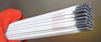
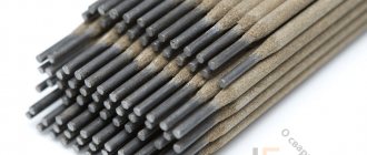
Carbon electrodes are round or rectangular rods made from electrical coal, which is a mixture of carbon (in the form of coke or anthracite), soot and binders (coal tar or liquid glass). Round ones are made by extrusion and supplied to consumers in the form of rods with a diameter of 4 to 18 mm and a length of 250÷700 mm, and rectangular ones are made by pressing in molds. In addition to GOST standard sizes, special rods of increased thickness (15x15, 20x20, etc.), manufactured according to specifications, are also used.
Carbon electrodes are much cheaper and stronger than graphite electrodes. But the resistivity of electrical coal is several times higher than that of graphite. Therefore, to improve the electrical characteristics of carbon rods, their surface is coated with copper.
As an example, the table shows the main parameters of round copper-plated carbon electrodes of the VDK brand with a length of 305 mm.
| Diameter (mm) | Operating current (A) | Metal Removal (g/cm) | Groove (width/depth) (mm) | Cutting thickness (mm) |
| 4 | 150÷200 | 10 | 6÷8/3÷4 | 7 |
| 6 | 300÷350 | 18 | 9÷11/4÷6 | 9 |
| 8 | 400÷500 | 33 | 1÷13/6÷9 | 11 |
| 10 | 500÷550 | 49 | 13÷15/8÷12 | 13 |
A prerequisite for using these products is to perform work only with straight polarity. When turned back on, the arc is very unstable, the quality of the weld due to carburization of the metal is low, the operating temperature of the carbon rod is much higher, which increases the rate of its evaporation.
Most popular brands
To better understand the properties of graphite electrodes and what consumables you can buy, let's look at a few of the most popular brands.
EG
Graphite electrodes made from petroleum coke and coal pitch. Designed to operate with a current density of no more than 25 A/sq. see Some manufacturers supply rods with nipples. Electrodes are used in electric arc apparatuses and ore-smelting furnaces. The most common models are EG 1 AND EG 2. They differ in resistance.
EGS
The rods are made from stone pitch and needle coke. They are used in steelmaking and refining applications.
EGP
Electrodes are designed for cutting. They consist of petroleum coke and coal tar pitch. The materials are additionally impregnated with pitch. They are used in ferroalloy furnaces and the metal foundry industry.
EGSP
The basis of these rods is needle coke with a special impregnation of coal tar pitch. They are used on electrothermal devices and electric arc apparatuses. The resistance of the electrodes varies depending on the diameter. The brand is represented by 2 models EGSP 1 and EGSP 2.
Types of carbon electrodes
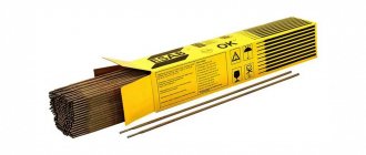
The regulatory framework for the production of domestic carbon electrodes is GOST 10720-75, which contains a description of three types of such products: VDK, VDP, SK, which can be produced either copper-plated or uncoated.
Air-arc round air-arcs should be manufactured with a length of 300 mm and four standard sizes in diameter. SK (welding round) - 250 mm long and six standard sizes in diameter. VAF (air-arc flat) - 350 mm long and two sections. At the customer's request, it is allowed to manufacture SK products with a linear dimension of up to 700 mm. In addition to domestic electrodes, the Russian market offers products from well-known international welding brands and manufacturers from East Asia. The Swedish concern ESAB offers over twenty types of copper-plated carbon electrodes. In addition to products used for direct polarity direct current welding, the ESAB range includes four standard sizes for alternating current welding. And the well-known German manufacturer of welding accessories ABICOR BINZEL, when advertising its products, focuses on the fact that it is made of “synthetic graphite” (i.e., graphitized carbon). It is likely that these products were pressed from powder obtained from the remains and scrap of metallurgical graphite electrodes.
In addition, there are pressed electrodes made of electrical and graphite carbon on the market, which are custom-made by manufacturers of carbon and graphite products according to TU 1915-086–00200851.
As a rule, they are rectangular rods with a thickness of 10, 20, 30 or more millimeters and are used for large-scale work at high welding currents: cutting metallurgical scrap, eliminating profits on castings, through cutting of thick metal, etc.
Welding Tips
When welding copper conductors, remember that first of all you need to prepare and clean the surfaces to be welded, and then securely fix them.
Welding of copper wires and busbars is carried out only in a top-down position, since molten copper has increased fluidity. In this case, boron slag flux is used. Another feature of this type of electrode is that the melting process is almost indistinguishable, since evaporation begins almost immediately (electrical coal melts at a temperature of 3800 °C, and evaporates at 4200 °C). The recommended sharpening angle for the ends of carbon rods is 60÷70°, but for welding non-ferrous metals they must be sharpened at an angle of 20÷40°. Sheet copper up to 4 mm thick can be welded without the use of filler rods (but with mandatory flanging of the edges), and over 4 mm - end-to-end with filler material and cutting the edges at an angle of 45°. Brass welding technology requires cutting edges at an angle of 60÷70° with blunting of the ends by 1÷2 mm. Welding is done by immersing the end of the rod, which must be completely enveloped in zinc vapor.
Figure 5 - Brass wires
Recommended welding current modes for different conductors
The magnitude of the welding current depends on the cross-section size and the number of strands in the twist: the thicker the twisted bundle, the greater the current value must be set on the welding machine:
- 2 cores, cross section of each 1.5 mm² - 70 A;
- 3 cores, cross section of each 1.5 mm² - 80-90 A;
- 2-3 cores, cross section of each 2.5 mm² - 80-100 A;
- 3-4 cores, cross section of each 2.5 mm² - 100-120 A.
The specified welding current modes are indicative. Wires from different manufacturers differ in chemical composition and declared cross-section, and welding devices also differ in their characteristics. Therefore, it is better to select the value of the welding current practically on a small section of the same wire. When choosing a mode experimentally, the optimal one will be when the arc is stable and the tip of the electrode does not stick to the welding site.
For modern inverter-type devices:
- stable welding discharge , ensuring high-quality welding work;
- When welding, liquid metal does not splash;
- the arc does not blind the welder due to the low melting point of copper;
- inverters are not heavy, their dimensions are small , which allows them to be carried to the installation site on a belt.
Carbon gouging
Gouging is the removal of a narrow surface layer using carbon arc welding.
The word itself originates from the verb “to plan,” since this process is somewhat similar to the processing of grooves on a planing machine. Gouging technology is based on heating the metal with an electric arc to boiling temperature, followed by blowing it out of the weld pool with a narrowly directed air flow. Gouging is carried out to depths of up to tens of millimeters, and its productivity, depending on the thickness of the carbon electrode and the current strength, is measured in grams of metal removed per centimeter of groove. When performing gouging, the electrode is moved forward evenly at an angle of 30÷45°, forming a groove that is several millimeters wider and deeper than the diameter of the electrode. Planing is carried out with a special air-arc cutter, which has an established slang name “planer”. The contact plate with air supply nozzles is located on the lower jaw of the planer, so the air flow is directed along the bottom of the electrode towards the weld pool (see figure below). The air supply should stop a few seconds after breaking contact between the electrode and the metal.
Figure 6 - Air direction during welding
The use of welding with carbon electrodes for connecting electrical busbars made of copper and aluminum is regulated in detail by the instructions of Roselectromontazh I 1.08-08. But it doesn't say anything about welding wires. At the same time, there are quite a lot of photographs on the Internet demonstrating the use of such welding when installing electrical wiring in ordinary apartments and office premises. However, we have not yet been able to find even a mention of a regulatory document regulating such technology. If you know anything about this, please write a comment on this article.
How to weld twists?
To prevent possible melting of the cable insulation, a metal radiator must be attached to the base of the twist. A clamp with a large surface that improves heat transfer will help remove excess heat from the twist. It is advisable that the radiator be made of copper, as it has high thermal conductivity.
Safety rules for welding work.
The twist welding process is preceded by a preparatory stage, during which the wires are freed from their sheaths and insulation. The length of the exposed cores must be at least 10 cm, then the twist will be no shorter than 5 cm.
When twisting the wires, you need to ensure that they fit as closely as possible to each other. You also need to ensure that their ends end up at the same level, otherwise some of the wires will end up outside the welded joint. If necessary, the end of the twist is cut off with side cutters.
Near the radiator, a ground clamp is attached to the twist, after which an electrode is brought to the tip of the wires. The contact time should not exceed 2 seconds. After it is interrupted during twisting, a small influx of spherical shape is obtained. The remaining twists are welded in the same way.