- September 12, 2020
- Repair Tips
- Ivan Gresko
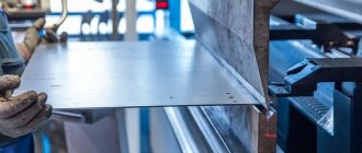
Many radio amateurs and home craftsmen are familiar with this heating device. It can be used to connect various parts made of ferrous and non-ferrous metals. Owners are often interested in the question: how to repair a soldering iron at home? The fact is that this tool can fail as a result of improper handling. Of course, you can take it to a workshop and have it done by a professional. However, many owners prefer to do it on their own.
How to fix a soldering iron? This is especially of interest to those who have just begun to master this heating device. In general, this task will not be difficult to cope with if you identify the cause of the breakdown and strictly adhere to a certain algorithm of actions. Information on how to repair a soldering iron at home is presented in this article.
Components of the tool
Before you are interested in how to repair a soldering iron at home, you should know how it works. In this case, if there is a breakdown, it will be easier for you to determine the cause and fix it. The soldering iron device is represented by the following elements:
- Copper rod. It is wrapped in insulating material and housed in a steel tube.
- Heater. This task is performed by nichrome thread.
- Sting. They use solder to directly connect metal parts.
- With a pen. Thanks to it, the master can hold the soldering iron.
- Cord equipped with a plug.
Description of design
The copper rod is an effective conductor of heat that flows from the heater to the tip. The rod is located in a steel tube wrapped in mica or glassy tissue. A wire is wound over the mica, which acts as a heating element. To prevent heat loss and short circuit, the nichrome winding is insulated, covered with asbestos for this purpose. The ends of the spiral are connected to the conductors of the power cord. To make the design more reliable and the connection point not to overheat from the heat generated, the nichrome spiral is bent in half and folded in half. Additionally, the point of contact of the spiral with the copper wire is crimped using an aluminum plate. In addition, the twisting area is covered with an insulating tube. All of the above elements are housed in a metal casing. It is mounted on a handle, which can be made of wood or thermoplastic. Inside the handle there is a special channel for the electrical cord. The housing is fixed to the metal tube using overlay rings. Those who are interested in how to repair a soldering iron at home should also know about the technical characteristics of the electrical appliance.
Simple from resistor
Calculation
The simplest soldering iron can be made from a wire resistor; this is a ready-made nichrome heater. It is also easy to calculate: when the rated power is dissipated in free space, the wirewound resistors heat up to 210-250 degrees. With a heat sink in the form of a sting, the “wireworm” maintains a long-term power overload of 1.5-2 times; The temperature of the tip will not be lower than 300 degrees. It can be increased to 400, giving a power overload of 2.5-3 times, but then after 1-1.5 hours of operation the soldering iron will need to be allowed to cool.
Calculate the required resistor resistance using the formula: R = (U^2)/(kP), where:
R – required resistance;
U – operating voltage;
P – required power;
k – the above power overload factor.
For example, you need a 220 V 100 W soldering iron for soldering copper pipes. The heat transfer is large, so we take k = 3. 220^2 = 48400. kP = 3*100 = 300. R = 48400/300 = 161.3... Ohm. We take a 100 W resistor 150 or 180 Ohm, because There are no “wireworms” at 160 Ohms, this rating is from the range of 5% tolerance, and “wireworms” are no more accurate than 10%.
The opposite case: there is a resistor with a power p, what power can you make a soldering iron from it? What voltage should it be powered from? Let's remember: P = U^2/R. Let's take P = 2 p. U^2 = PR. We take the square root of this value and get the operating voltage. For example, there is a 15 W 10 Ohm resistor. The power of the soldering iron is up to 30 W. We take the square root of 300 (30 W * 10 Ohm), we get 17 V. From 12 V, such a soldering iron will develop 14.4 W, you can solder small things with low-melting solder. From 24 V. From 24 V – 57.6 W. The power overload is almost 6 times, but occasionally and for a short time it is possible to solder something large with this soldering iron.
Manufacturing
Making a soldering iron from a resistor
How to make a soldering iron from a resistor is shown in Fig. higher:
- We select a suitable resistor (item 1, see also below).
- We prepare the parts of the tip and fasteners for it. Use a file to select a groove on the rod for the ring spring. Threaded blind holes are made for the bolt (screw) and the tip, pos. 2.
- We assemble the rod with the tip into the tip, pos. 3.
- We fix the tip in the resistor-heater with a bolt (screw) with a wide washer, pos. 4.
- We attach the heater with the tip to a suitable handle in any convenient way, pos. 5-7. One condition: the heat resistance of the handle is not lower than 140 degrees; the resistor terminals can heat up to this temperature.
Subtleties and nuances
The soldering iron described above made from 5-20 W resistors was made by many (including the author in his pioneer days) and, having tried it, they were convinced that it could not be used seriously. It takes an unbearably long time to heat up, and it only solders small things with a poke - the ceramic layer interferes with the heat transfer from the nichrome spiral to the tip. This is why the heaters of factory soldering irons are wound on mica mandrels - the thermal conductivity of mica is orders of magnitude higher. Unfortunately, it is impossible to roll mica into a tube at home, and rolling 0.02-0.2 mm nichrome is not for everyone either.
But with soldering irons from 100 W (resistors from 35-50 W) the matter is different. The ceramic thermal barrier in them is relatively thinner, on the left in the figure, and the heat reserve in the massive tip is an order of magnitude greater, because its volume grows by the cube of its dimensions. It is quite possible to qualitatively solder a joint of 1/2″ 200 W copper pipes with a resistor soldering iron. Especially if the tip is not prefabricated, but one-piece forged.
Wirewound resistors, suitable and unsuitable for making soldering irons
Note: wirewound resistors are available for dissipation power up to 160 W.
Only for the soldering iron you need to look for resistors of old types PE or PEV (in the center in the figure, still in production). Their insulation is vitrified and can withstand repeated heating to light red without losing its properties, only darkening as it cools. The ceramic inside is clean. But the resistors C5-35V (on the right in the figure) are painted, and so are the insides. It is completely impossible to remove paint from the channel - ceramics are porous. When heated, the paint becomes charred and the tip sticks tightly.
How does the device work?
Those who do not know how to repair a soldering iron with their own hands should familiarize themselves with the principle of operation of an electrical device. The soldering iron functions by converting electricity into heat. As a result, heat is transferred through the heated spiral to the rod, as a result of which the tip becomes heated. You should know that in the area where soldering is carried out, the temperature varies from 400 to 4500 °C. As a result, a mixture of viscous-liquid consistency is formed. Subsequently, it fills the cavity between the parts being soldered. When the mixture cools, the metal parts are securely connected.
About voltage
If there is a need to repair the device, take into account the voltage indicator. Depending on the model, its value may be:
- 220 V. This value is mainly found in domestic models.
- 12-42 V. Devices with a reduced voltage transformer are used in conditions with high levels of dust or humidity in order to protect the technician from electric shock.
- 5 V. Miniature USB soldering irons have this indicator.
Rules for using power tools
On the shelves of construction stores you can find different models of electric soldering irons that operate on mains power - from 12 to 220 W. The process of choosing a tool should take into account the safety of the working craftsmen and the voltage in the electrical network at the work site.
Attention
In rooms with high humidity, where grounding is provided, it is permissible to use soldering irons with a power of 36 Watt, 25 Watt and lower. In this case, it is necessary to ground the instrument body.
If the instrument is made independently, then a thin wire will be required for its correct reconstruction. It will be wound onto a spiral. The required power is from 12 to 100 W, even more is possible. The material will spread evenly over the surface of the plates if the melting temperature exceeds the temperature in the soldering iron itself.
About power
This technical characteristic determines the functionality of the soldering iron. For example, for home use to work with wires, a power of 30 W will be sufficient. These soldering irons are mainly used by radio amateurs. Professional installers operate devices with power up to 60 W. Such devices are convenient for soldering wires and cables of various diameters. Soldering irons over 60 W are used in automobile workshops. These soldering irons are suitable for tinning large metal products. It is noteworthy that the higher the power indicator, the larger and heavier the device itself. With increasing power, the size of its tip (sting) also increases. Thus, a soldering iron with more power will heat up the soldering area better. What to do if your electric soldering iron breaks down? How to fix the device?
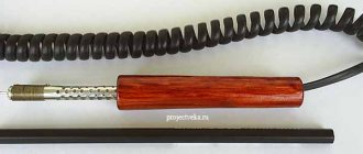
Applications and types
- The AC electric soldering iron with spiral heating of the core operates from a standard power supply network for household equipment at 220V 50-60Hz.
- A cordless electric soldering iron is used for desoldering wires and other small-sized elements where high power up to 15 W is not required;
- There are varieties of gas soldering irons that are used for strong heating of metal elements and refractory alloys;
- To work with low-melting tin during the installation and repair of radio equipment, pistol-type soldering irons with pulsed voltage supply are widely used. When you press the trigger, the tip of the soldering iron heats up; after soldering is completed, the trigger is released and the heating element cools down;
- Soldering irons with ceramic rods have a long service life and allow you to select the desired temperature mode and power consumption;
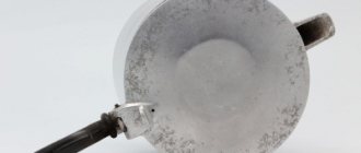
Soldering iron with ceramic tips on the rod
- Induction soldering irons are widely used. An inductive coil creates a magnetic field on the ferromagnetic tip, which heats the core. When the magnetic properties of the core are lost, heating stops; this is a significant drawback of such models.
An electric soldering iron is used as a hand tool. With its help, solder is melted to a liquid state, which fills the cracks and irregularities of heated metal elements at the joints, for which alloys of low-melting metals are used:
- tin;
- lead;
- zinc;
- nickel;
- copper and others.
The melting temperature of solders must be less than the melting temperature of the metal elements being connected.
The industry produces different types of soldering irons. The most commonly used in industry and at the household level are spiral soldering irons, which are worth describing in more detail.
Repairing a burnt-out soldering iron. Where to begin?
Before you repair the soldering iron yourself, you should disassemble it. This is necessary in order to get to the heating element, namely the nichrome wire. For this purpose, unscrew the mounting bolts and disassemble the device. Overall you will only need to remove two bolts. When they are removed, take out the soldering iron “filling”, which is contained inside the metal case. To do this, you will have to carefully open the case itself. At this stage you must be very careful not to damage the thin and very fragile insulation. If handled carelessly, it may fall apart.
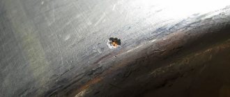
Restoring the heating element
When you get to the heating element, carefully inspect the nichrome wire. It may happen that several turns of wire are burnt out. To restore the heating element you need to do the following. Take an old broken soldering iron and remove a small piece of wire from it. Next, connect it and wind it instead of the burnt out turns. According to experts, when connected without adding wire, the spiral will burn out again due to reduced resistance. You need to wind it so that the turns do not touch each other. Then connect the power cord.
Why doesn't the soldering iron heat up? How to fix it?
Most often, the cause of this malfunction is poor contacts. First check the voltage supply. If it turns out that the current power is normal, then most likely the malfunction is caused by an incorrect location of the tip. This happens especially often in electrical appliances with retractable rods and screw terminals. Often the tip wears off or for some other reason ends up being too protruded from the body. If the working surface is located normally, then its end part in the form of a core is completely located in a mica tube. Thus, the contact of the rod with the heating element occurs fully, due to which the tip heats up more. If it is removed from the tube at least halfway, the heating intensity will decrease significantly. Repairing the device is easy. Home craftsmen insert the sting deeper into the body and fix it. It may be that the rod turns out to be too short. In this case, it is replaced. Also, the soldering iron may not work due to scale on the tip. It is removed, if necessary, and then the surface is cleaned using ordinary fine-grained sandpaper or a needle file.
The sting is then heated and dipped in rosin, after which its tip is rubbed on a braid with solder. As a result of such actions, the rod will be covered with an even layer of solder. Experts recommend performing this procedure more often with soldering irons equipped with copper rods, since scale forms on them faster. Also, the soldering iron may not heat up due to improper sharpening of the tip. For effective heat transfer, the working surface must have the shape of an oval bevel.
Simplest
Let's not get into the complications for now. Let's say we need a regular 220V soldering iron without any fuss. We go to choose and see that the difference in prices reaches 10 times or more. Let's figure out why. First: heater, nichrome or ceramic. The latter (not “alternative”!) is practically eternal, but if the soldering iron is dropped on a hard floor, it can break. The tip of ceramic soldering irons is necessarily non-replaceable, which means you need to buy a new one. And a nichrome heater, if the soldering iron is not forgotten to be turned on at night, lasts more than 10 years; with occasional use - over 20. And in extreme cases, it can be rewound.
The difference in price has now been reduced to 3-4 times, what else is the matter? In a sting. Nickel-plated copper with special additives is poorly dissolved by solder and burns very slowly in the soldering iron holder, but is expensive. Brass or bronze heats up worse, and it is impossible to solder SMD with it - the temperature hysteresis cannot be brought back to normal due to the thermal conductivity of the material being much worse than that of copper. The red copper tip is eaten by solder and swells quite quickly from copper oxide, but it is cheaper.
Note: a tip made of electrical copper (a piece of winding wire) is unsuitable for a conventional soldering iron - it quickly dissolves and burns. However, for SMD such a sting is just right, its thermal conductivity is the highest possible, and thermal inertia and hysteresis are minimal. True, you will have to change it often, but the sting is about the size of a match or less.
Burning and swelling of the red copper tip can be dealt with simply by being careful: after finishing the work and allowing the soldering iron to cool, take out the tip, peel off the oxide, tapping it on the edge of the table, and blow out the channel of the soldering iron holder. Solder dissolution is worse: sharpening the tip is often inconvenient and it quickly wears out.
You can make a soldering iron tip from ordinary red copper many times more resistant to the action of molten solder by not sharpening its working end, but by forging it to the desired shape. Cold copper can be forged perfectly with an ordinary metalworker's hammer on the anvil of a bench vise. The author of this article has had a forged tip in the ancient Soviet EPSN-25 for more than 20 years, although this soldering iron is in use, if not every day, then certainly every week.
About using solder
If you notice that your tool heats up weakly, then most likely you have chosen the wrong solder. For example, for low-power electrical appliances rated at 26 watts, it is not recommended to use low-tin solder (POS-30). You will not melt this solder with this soldering iron. It is best to get POS-60 or POS-61 solder. Other solders with a high lead content are suitable for higher power electrical appliances.
About rewinding an electrical appliance
Beginners often ask the question: how to rewind a soldering iron? Judging by numerous reviews, very often device repair is limited to replacing the burnt nichrome winding. Before starting this procedure, use a special table to calculate the diameter of the wire, as well as the number of turns. For example, how to repair a 200W soldering iron? To do this, select the soldering iron power consumption indicator of 200 W (in the left column of the table). To this value, the winding resistance at a voltage of 220 V will be 242 Ohms. It will be best to rewind the entire reel.
In this case, there will be no weak points in the device. It is very important that the new wire has the same parameters as the old winding. If it is not possible to select a similar insulating layer, then it can be replaced with mica in the form of a tube or plates. You can also use heat-resistant fiberglass or asbestos gaskets to make an insulating layer. After the insulation is ready, wind the winding (first layer) around it. Next, put another layer of insulation on the turns and wind the winding again (second layer). Now all that remains is to connect the ends of the wire to the power cord.
Sequence of calculation of electrical circuit parts
Selecting the power of the soldering iron
The main indicator of the efficiency of the design is the amount of heat generated at the tip when electric current passes through it. Its strength, specially increased by the short circuit mode, heats up the copper of the tip.
The current passing through the tip of my soldering iron is slightly more than 200 amperes. I specially checked it with a current clamp. But the voltage, even in idle mode, is less than tenths of a volt. Therefore, it does not pose any particular danger when soldering.
The product of the current passing through the power winding and the voltage across it is characterized by the secondary or output power of transformer S2. This is the quantity that interests us. However, to simplify the calculation, we will begin to operate with primary power S1, which determines electricity consumption.
It differs by the coefficient of performance - efficiency. Its value of 65 watts is taken as the basis for the industrial design shown in the first photo. For my purposes, I chose 80 watts.
Effect of efficiency
The design relationship between the secondary power of transformers for radio-electronic devices and efficiency is given in the table.
| Efficiency | Power in watts |
| 0,95÷0,98 | ≥1000 |
| 0,93÷0,95 | 300÷1000 |
| 0,90÷0,93 | 150÷300 |
| 0,80÷0,90 | 50÷150 |
| 0,50÷0,80 | 15÷50 |
Set of magnetic core with transformer iron plates
The magnetic characteristics of the magnetic core and the transformer as a whole are determined by:
- volume of iron;
- and its properties.
We cannot particularly influence the second parameter, because we use the iron from an old transformer that came to hand. Therefore, we use the simplest averaged method, without going too much into complex coefficients, corrections, and graphs.
For a soldering iron, we can choose a magnetic core of one of the following shapes:
- rectangle;
- W-shaped.
Its cross-sectional area for each case is shown in the picture. Formulas for calculation are also given here.
Having chosen the primary power of the soldering iron in watts and knowing the shape of the magnetic circuit, we calculate Qc - the cross-sectional area using the empirical formula.
Having determined it and measured the size “A” on the iron, you can calculate the depth “B”, which will need to be dialed with a certain number of plates.
Calculation of wire for coil winding
Diameter determination
Based on the primary power, for example, 80 watts and a voltage of 220 volts, it is not difficult to calculate the current that will flow through the primary coil.
80/220=0.36 A.
Next, the empirical formula works: d=0.8√I.
Where d is the wire diameter in mm, and I is the current in amperes.
Determination of the number of turns
We use an empirical law called the number of turns per volt - ω'. It is calculated:
ω'=45/Qc.
Primary coil
Qc has already been calculated earlier. Having determined ω', this value should be multiplied by 220, because we have such a voltage in the primary winding, and not one volt.
Secondary coil
For the backlight circuit, the voltage is 4.5 volts. We multiply the resulting value ω' by it.
Both calculated values: diameter and number of turns are averaged. They will have to vary within small limits, taking into account the fact that the space in the magnetic circuit window is limited. It is better to immediately underestimate the diameter of the wire - the soldering iron works in short-term mode.
But you should be more careful with the number of turns. They greatly influence the current-voltage characteristic of the soldering iron and the overall pattern of tip heating.
The power coil is made with two turns.
Broken wiring
How to fix a soldering iron with your own hands if the electrical cord is faulty? Judging by numerous reviews, this reason for device failure is considered the most common. You can correct the situation on your own. Many owners simply replace the plug or cord. Of course, it all depends on which part the break occurred in. This defect is correctable, and you can fix it yourself. To determine exactly where the break occurred, you will need to acquire a special device, namely a multimeter. Use the probes of this device to examine the wiring. In the place where the break occurred, you need to reconnect the wires and insulate them.
How to fix a soldering iron with a regulator yourself?
Such electrical devices are equipped with a special device for adjusting the temperature of the tip. Using this soldering iron is quite convenient. The master knows that it is heating up thanks to the LED, which glows while the tip is heating. When the working surface reaches the desired temperature, the LED will go out, after which you can begin soldering. According to reviews from owners of such soldering irons, these power tools often fail. For example, there are times when buttons come off or an LED does not light up. Some home craftsmen wrap buttons with insulating tape. To repair the device, you must first carefully disassemble it. When you do this, you will see the op amp. It is a microcircuit in which, most likely, one of the small batteries has become disconnected. It needs to be reattached. For this purpose, you first need to clean the “legs” of the battery, tin them, and then solder them in their original place. After completing these steps, the soldering iron can be assembled and tested.
Elimination of tip overheating
Refinement of the power regulator
A homemade contact sensor is made from an old Soviet capacitor and balls from a bearing. The device is placed on the factory board without modifications to the case. When the soldering iron is placed on the stand with the tip up, the sensor opens the circuit and the heating temperature decreases. When we start soldering, the contacts inside close and the tip warms up to the set temperature in accordance with the position of the regulator.
Let's look at a few more examples of such modifications in relation to various models of soldering devices.