A cutter for cutting trapezoidal threads is shown in Fig. 200. The angle between the side cutting edges of the cutter should be equal to 30°; The length t of the leading edge is taken according to the profile of the thread being cut. All angles (α, α1, α2) are selected in the same way as the angles for cutting a rectangular thread. And in this case, holders are used to secure the cutters (see Fig. 199).
The cutter for cutting trapezoidal threads is sharpened according to a pattern similar to that used when sharpening cutters for triangular threads, and in the same order. The sharpened cutter is finished.
Rice. 200. Cutter for cutting trapezoidal threads
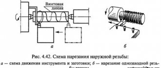
Techniques for cutting trapezoidal threads . Installation of the cutter when cutting trapezoidal threads is done in the same way as for rectangular threads. Threads with pitches up to 3 mm are cut with one cutter having a full profile. Cutting threads whose pitch exceeds 3 mm is carried out in several stages (Fig. 201, a). A helical groove is cut with a groove cutter, the width of which is 0.1-0.2 mm less than the width of the thread root. The diameter of the groove “along the bottom” must be equal to the internal diameter of the thread being cut. After this, two cutters (right and left) give the helical groove a trapezoidal shape, and the width of the groove, measured by the outer diameter, should be 0.3-0.4 mm less than the final one. Each of the incisors must have an apex angle of 30°; the length of the front cutting edge of the cutter is made 1-3 mm less than the width of the cavity of the thread being cut. The final finishing of the thread is done with a cutter having a full profile. Only the sides of the thread profile are finished with this cutter.
Rice. 201. Techniques for cutting trapezoidal threads
Another, very productive method of cutting trapezoidal threads is shown in Fig. 201, b. A preliminary groove is cut using a cutter whose width is 0.3-0.4 mm less than the final width of the helical groove, measured by the average diameter of the thread. The diameter of the groove, measured “along the bottom,” should be 0.3–0.5 mm larger than the average thread diameter.
The preliminary groove is then deepened to the inner diameter of the thread.
The width of the cutter used should be 0.2 mm less than the final width of the cavity. The profile is finished sequentially with two cutters that have the full profile of the thread being cut. The first of the cutters has a concave (grooved) front surface, which provides greater ease of chip separation and a clean thread surface. The second cutter should have a flat front surface.
Checking trapezoidal threads . To check trapezoidal threads, limit gauges are used, similar in design to the limit gauges for triangular threads. The profile of the trapezoidal thread is checked with the protrusion C of the template (Fig. 202). If it is necessary to determine the average diameter of a trapezoidal thread, it is checked indirectly. To do this, the template is applied to the thread, as shown in Fig. 202. If the bottom of the template recess touches the top of the thread profile, and points A and B touch its sides, the average diameter of the thread is correct.
Rice. 202. Template for checking the profile and average diameter of trapezoidal threads
It should be noted that this method of checking the average diameter is rough, since the outer diameter of the thread, on the accuracy of which the result of the check in Fig. 202, is processed with a low degree of accuracy. An exception to this are trapezoidal thread screws (lead screws), in which the side surface serves as a mounting base, when cutting threads using steady rests. The outer diameter of such screws is therefore more accurate than conventional ones.
Trapezoidal threads designed to transmit movement are divided into large, normal and small. Depending on the pitch and diameter of the thread, various methods of their manufacture are used. For example, threads with a pitch of up to 4 mm are cut with a cutter whose profile matches the thread profile. In this case, the cutter is installed according to the template so that the main cutting edge of the cutter is parallel to the axis of the part.
Trapezoidal thread cutting
A cutter for cutting trapezoidal threads is shown in Fig.
200. The angle between the side cutting edges of the cutter should be equal to 30°; The length t of the leading edge is taken according to the profile of the thread being cut. All angles (α, α1, α2) are selected in the same way as the angles for cutting a rectangular thread. And in this case, holders are used to secure the cutters (see Fig. 199). The cutter for cutting trapezoidal threads is sharpened according to a pattern similar to that used when sharpening cutters for triangular threads, and in the same order. The sharpened cutter is finished.
Rice. 200. Cutter for cutting trapezoidal threads
Techniques for cutting trapezoidal threads . Installation of the cutter when cutting trapezoidal threads is done in the same way as for rectangular threads. Threads with pitches up to 3 mm are cut with one cutter having a full profile. Cutting threads whose pitch exceeds 3 mm is carried out in several stages (Fig. 201, a). A helical groove is cut with a groove cutter, the width of which is 0.1-0.2 mm less than the width of the thread root. The diameter of the groove “along the bottom” must be equal to the internal diameter of the thread being cut. After this, two cutters (right and left) give the helical groove a trapezoidal shape, and the width of the groove, measured by the outer diameter, should be 0.3-0.4 mm less than the final one. Each of the incisors must have an apex angle of 30°; the length of the front cutting edge of the cutter is made 1-3 mm less than the width of the cavity of the thread being cut. The final finishing of the thread is done with a cutter having a full profile. Only the sides of the thread profile are finished with this cutter.
Rice. 201. Techniques for cutting trapezoidal threads
Another, very productive method of cutting trapezoidal threads is shown in Fig. 201, b. A preliminary groove is cut using a cutter whose width is 0.3-0.4 mm less than the final width of the helical groove, measured by the average diameter of the thread. The diameter of the groove, measured “along the bottom,” should be 0.3–0.5 mm larger than the average thread diameter.
The preliminary groove is then deepened to the inner diameter of the thread.
The width of the cutter used should be 0.2 mm less than the final width of the cavity. The profile is finished sequentially with two cutters that have the full profile of the thread being cut. The first of the cutters has a concave (grooved) front surface, which provides greater ease of chip separation and a clean thread surface. The second cutter should have a flat front surface.
Checking trapezoidal threads . To check trapezoidal threads, limit gauges are used, similar in design to the limit gauges for triangular threads. The profile of the trapezoidal thread is checked with the protrusion C of the template (Fig. 202). If it is necessary to determine the average diameter of a trapezoidal thread, it is checked indirectly. To do this, the template is applied to the thread, as shown in Fig. 202. If the bottom of the template recess touches the top of the thread profile, and points A and B touch its sides, the average diameter of the thread is correct.
Rice. 202. Template for checking the profile and average diameter of trapezoidal threads
It should be noted that this method of checking the average diameter is rough, since the outer diameter of the thread, on the accuracy of which the result of the check in Fig. 202, is processed with a low degree of accuracy. An exception to this are trapezoidal thread screws (lead screws), in which the side surface serves as a mounting base, when cutting threads using steady rests. The outer diameter of such screws is therefore more accurate than conventional ones.
Slicing rules
The quality of the profile depends on many factors:
- Workpiece errors. Underestimation or overestimation of the diameter of the rod and hole, respectively, is the reason for the incomplete height of the turns. The difference in height along the length is a consequence of the taper of the original surface.
- A torn surface is caused by a dull tool, high speed, or incorrectly chosen lubricant.
- Shrinkage of the nut along the average diameter is typical with similar wear of the tap.
- The stretching of the coils occurs due to the braking of the self-extending mandrel.
- Breaking the nut along the average diameter is possible from a large rake angle, which facilitates the pressing of the tap feathers.
To avoid this you must:
- Choose the equipment and cutting method wisely.
- Prepare the workpiece according to the technological documentation or the instructions in the reference tables.
- Select the correct cutting modes and coolant.
- Set up the machine for processing, calculate and assemble the guitar if necessary.
- Control sharpening and installation of the cutter according to the template.
- Check the first finished parts, make adjustments, and periodically repeat the check in the future.
- Monitor the serviceability of devices and sharpen tools in a timely manner. Thread quality control Providing the required service characteristics of the connection is determined by the compliance of the actual values: outer, inner, average diameters, half of the profile angle, pitch. Checks are performed:
- Calibers. They control thread diameters in mass production.
- Pedometers (threaded templates), micrometers with replaceable inserts. The first to check for clearance are P and α/2, the second are equipped with a set of replaceable inserts for different ratings and are designed to measure the average diameter of bolts. They are used in small-scale workshops, measurements are not accurate.
- Accurate measurement of the average screw diameter is performed using three wires, a micrometer or an optimometer. The error of the latter is up to 2 microns.
- Particularly important parts are checked using instrumental microscopes, which make it possible to reliably determine diameters, pitches, and angles.
trapezoidal thread
Please tell me how to cut a trapezoidal thread yourself? External and internal)))
wawbew You must have a lathe with a steady rest, and at least several years of experience.
Alex___dr teks, there is neither one nor the other, then another question is whether it is realistic to buy a stud somewhere (a range of sizes is acceptable) M8-M10-M12-M14-M16 mm with a metric thread and a thread pitch of 3-4mm
wawbew Threaded rods M14 and M16 will have a pitch of 2mm; M18, M20, M22 will have a pitch of 2.5mm; M24 - 3mm.
those. Can’t this even be done to order as an exception?
wawbew Back to the lathe and trapezoidal threading. In a trapezoidal thread, a 3mm pitch starts from a thread diameter of 10mm, a 4mm pitch from 16mm.
those. basically according to my parameters, i.e. M10 etc is suitable for a trapezoidal thread, did I understand correctly?
wawbew If you need a large pitch with a relatively small diameter - yes.
Thank you very much, let's look (c) in order to cut such threads, the machines do not have to be CNC?
wawbew wrote: in order to cut such threads, the machines do not have to be CNC?
You don't need a CNC machine, a regular lathe is enough. In general, you don’t even need a machine; you can easily find a die or tap
newbas wrote: you can freely find a die or tap
And where did you see these? It’s not that I haven’t seen it, it’s actually the first time I’ve heard about such
It is much easier to find some working old turner from the once numerous factories and institutes. Or there are no more factories left in Krasnodar (:
2wawbew Where is this needed? Maybe we can recommend something else. I remembered that on my ancient jack there is a screw with a nut with a trapezoidal thread of only dia. there EMNIP is larger, about 18mm
» > Download the price list and find it. For example, I ordered a ladder M12x2 left
Or there are no more factories left in Krasnodar
There are none left, but I have a lathe. It’s just faster and easier to use a ready-made tap - the hole is through, and my size is F12. And if there is no machine, then only a tap and a die
newbas wrote: In general, you don’t even need a machine, you can easily find a die or tap
Vidis wrote: And where did you see these?
I join the question.
Vidis wrote: It’s not that I haven’t seen it, it’s actually the first time I’ve heard about such
2Alex___dr Gugel rules. It’s just that such threads are not very common - jacks, lead screws. I don't know anymore.
Only this is a rather unique tap.
newbas wrote: Just using a ready-made tap is faster and easier -
But not cheaper. » > Neither the reference book nor Google knows about dies for trapezoidal threads.
Vidis wrote: 2wawbew Where is this needed? Maybe we can recommend something else.
Depending on the load on the thread, screws with a pitch of less than 3 mm can be used. Only the speed of movement will decrease or the number of turns of the handle will have to be made more.
Here in hardware they sell two-meter studs M8-M10-M12-M16. .
Alex___dr wrote: Message from Vidis And where did you see these?
I join the question.
Only special orders at factories. But he held it in his hands.
MMR ladder 12x2 left - set (No. 1 and No. 2) - 1180 rubles with VAT » >
when I was a turner on my native collective farm (I turned there for 3 years, all sorts of crap had to be repaired), I cut such threads on a regular 16v20 lathe. True, they didn’t come across diameters smaller than 16. But 16 at a length of 600 with normally bored jaws was cut in half an hour. Screw + 25 minutes nut. It cost about 200 rubles (a bottle of good vodka, some money).
Types and properties of cutters
Classification
In practice, cutters for external and internal threads with a rectangular section holder are used. Less common are disc, prismatic, sharpened along the front surface. The working profile of all corresponds to the dimensions of the screw groove. In the direction of the cut spiral, left and right ones are released.
There are solid and prefabricated instruments. The first ones are mainly made of high-speed steel, small section or disk. The bulk is equipped with cutting plates secured by soldering with refractory solder or mechanically, allowing replacement when worn.
Threaded cutters: external (Fig. 1), internal (Fig. 2)
Features that a trapezoid in thread provides
Original angles - profile at 15-40 0 and rise at 30 0 - determining the pattern of grooves;
Minimal friction (with proper selection of lubricant);
Self-braking, virtually eliminating the possibility of part deformation, even if it is subject to severe loads;
Impressive wear resistance (better than tubular or rectangular).
These properties are most clearly manifested in notches with a medium pitch: with their use, fairly accurate axial movements are achieved.
The easiest way to check the distance between the turns is with a caliper: measure the area on the rod, count the number of grooves, divide the found length by this number, get the result, check it with the reference data and make sure that it is within the normal range.
Now about why in the accompanying documentation you can often see the entry “trapezoidal thread Tr”: GOST 9484-81, which also regulates markings, establishes that when applying symbols the Latin alphabet should be used. And these two letters indicate the type of notches.
This profile design has a number of advantages:
When placed in the middle of a double radius, it is not difficult to identify radial clearances.
With it, complex devices and functionally complex objects can be repeatedly dismantled and constructed, and the process of their construction is simplified.
Due to the screw and nut, it ensures the conversion of rotation into translational motion, which means it has a positive effect on the overall performance of the mechanisms.
Allows you to adjust the compression force as needed, which speeds up the assembly of functional units.
Does not reduce the strength or other useful characteristics of the finished product - the quality of the latter is affected by the material, and not the number or geometry of the turns.
But trapezoid carving, the dimensions of which we will consider below, also has certain disadvantages:
If friction is still observed, it will provoke the appearance of significant stresses in the areas of the depressions.
This cutting pattern is not suitable for mechanisms used under strong vibrations - with constant vibrations, the fasteners can be unscrewed arbitrarily.
High cost in multi-pass design - they cost relatively high, are demanding on the technological base, and their production consumes a lot of electricity and time.
Therefore, it is not relevant everywhere, but in strictly defined areas - it is applied to specific parts, the number of which is usually extremely limited.
Trapezoidal thread: diameters and pitches according to GOST 24737-81
This interstate standard specifies values up to 640 mm for the cross-section and up to 24 mm for the distance between adjacent turns. But we will focus only on common values that are used frequently, and not in isolated cases.
Focus on these reference data when choosing a cutting option and remember: standard values of geometric parameters are the key to high compatibility of parts and especially fasteners.
Let's look at the most common and used design options today.
Trapezoidal thread left
It is applied with a flat contour blade rotating counterclockwise (as if from the observer).
This type of connection has been known perhaps the longest, but even now it remains relevant - in the following areas: In mechanical engineering - for fixing various parts on the machine shaft; it practically eliminates self-twisting of the workpiece during its processing.
As a universal fastener - wheels of SUVs and trucks, radiator nipples in heating systems, fan blades, bicycle units, motor gearboxes, circular saws, chucks with drills, and so on.
To control the trajectory of cutting and other tools - it is a kind of means of stopping production when dangerous situations arise.
In the automotive industry - to protect original factory components from counterfeiting.
It is very easy to distinguish it from others - by the letter “L”, with which it is required to be marked.
Right
This trapezoidal thread, according to GOST standards, is applied clockwise - a flat contour blade creates it, moving along in relation to the observer’s position. This is the main type of notch on screws, bolts, nuts and studs, and most screws and dowels used on an industrial scale also have it.
It is not difficult to understand that it has exactly this direction: just place the fastening element on your palm with the chamfer facing up and see where the turns are directed - they should come from you. Another obvious indicator is the letter “R” on the side of the product. Although it is not difficult to fake this option of applying grooves, that is why the same manufacturers of auto components are indifferent to it.
Where right-hand cutting is actively used is in the production of oxygen cylinder reducers in order to prevent an emergency when using them.
Single-start trapezoidal thread: main dimensions
Its pitch and diameter are regulated by interstate standards 24739-81 and 25347-82, along with the maximum possible processing tolerances, and will be given below. Now we want to focus on such a distinctive feature as the geometry of the pattern.
It got its name because it is performed by moving one blade. And it’s quite easy to determine that this is it: you just need to look at the end of the fastening element - 1 end of the turn should go out to it, but no more.
The distance between adjacent threads always coincides with the stroke value, so choosing, adjusting and maintaining it during application is relatively simple (and this is its advantage). The disadvantage is the relatively low strength of the connection of the final product and is explained by the fact that the internal diameter is too short to ensure reliable contact. Therefore, it is problematic to transfer significant loads with it, which means it is of limited use.
It will not be difficult to recognize it by its marking - the Latin letter “H”.
Multi-start ladder thread: GOST, dimensions
You probably already understood how it differs from the previous one: its groove pattern is formed by several blades at once. Therefore, on one thread there are 2 or 3 turns at once. In practice, it is its two- and three-way varieties that are most in demand, which means we will consider them as examples.
Such notches are relevant for tension structures - they are:
Application
Let us immediately emphasize that due to the excellent braking properties and the ability to withstand significant friction without deformation, literally all of its varieties do not require additional fastening. Therefore, in most situations it becomes a lead screw - a kind of drive for presses.
In practice, Tr (trapezoidal thread GOST 9484-81) helps solve the following problems:
Control the trajectory of actuators, lifting and other mechanisms.
Feed and stop movement on machines.
Ensure the movement of workpieces and products along the conveyor belt to the assembly point.
Support the press (and similar machines) in a given direction, most often vertical.
It is also applied to the surfaces of parts that are components of regulators, machine tools, and complex equipment.
The list of main areas of its use:
And the secondary industry is parts of motor gearboxes.
Mechanical engineering – functional units of various units.
Steam locomotive engineering – braking devices for electric locomotives operating in mines.
And separately, robotics with ultra-precise design (in especially critical and isolated cases).
Rules for sharpening turning tools
In order for the processing of workpieces on metal lathes to be effective, high-quality and accurate, the cutters should be regularly sharpened, thereby giving their working part the required shape and obtaining angles with the required parameters. Only tools whose cutting part is made in the form of a disposable carbide plate do not need sharpening. To perform such an important procedure in large manufacturing enterprises, machines with special devices are used, and a separate structural unit is engaged in this.
In order to sharpen a turning tool with your own hands on a home machine or do it in a small enterprise, you can use various techniques. This procedure can be performed using chemical reagents or using conventional grinding wheels. It should be noted that sharpening turning tools on specialized or universal machines that use an abrasive wheel is the most inexpensive but effective method of giving cutters the required geometric parameters.
Options for sharpening cutters with cutting inserts
Of course, the highest quality metal turning tools are sharpened on a machine specially designed for this procedure. If you don’t have such equipment at your disposal, you can use a universal machine with a grinding wheel. When choosing such a circle, it is important to pay attention to the material from which the working part of the tool being processed is made. So, in order to effectively sharpen a carbide cutter, you will need a carborundum wheel, which has a characteristic green color. Tools, the working part of which is made of carbon or high-speed steel, are perfectly processed on machines with medium-hard wheels made of corundum.
Sharpening of turning tools for metal can be done without cooling or with cooling, which is more preferable. If sharpening is carried out with cooling, then cold water should be supplied evenly to the place where the turning tool comes into contact with the grinding wheel. In the case when cooling is not used during the sharpening process, after sharpening it is impossible to immediately cool the tool sharply: this can lead to cracking of its cutting part.
You can learn how to sharpen turning cutters on a sharpening machine with your own hands using an instructional video. When performing this procedure, it is important to adhere to a certain sequence. First of all, the rear main surface is processed on the grinding wheel, then the rear auxiliary surface, and lastly the front surface is sharpened. The last stage of sharpening is processing the tip of the cutter - giving it the required radius of curvature.
During the sharpening process, the cutter is constantly moved in a circle, trying not to press it too hard (this can be seen in the video). It is necessary to adhere to this recommendation so that the surface of the circle wears evenly, and also so that the cutting edge of the turning tool is as smooth as possible.
Trapezoidal thread: dimensions table
Its main geometric characteristics are:
Nominal diameter (nominal diameter) is 1.5-48 mm.
The average angle is 30 degrees.
The pitch - the distance between adjacent turns (at identical points) - lies in the range of 0.75-24 mm.
The gap is up to a maximum of 0.5 mm.
All this is official statistical data, given in even more detail in the interstate standard 24737-81. We will present the main ones right now – in the most visual format:
How to thread a bolt and nut
The question of how to cut the thread of a bolt or nut is far from idle. During repairs, apartment and house owners are faced with the need to restore old threads of anchors, bolts, nuts, or simply threads found in metal plates.
Or you may even need to cut a new thread on the bolt or nut. For professional turners or mechanics, this task does not present any difficulties, but those who have never encountered such a process need to arm themselves with some theoretical knowledge, which is outlined in this article.
Classification, decoding and diagrams of threaded threads on a lathe
Thread cutting on a lathe is an alternative to using specialized equipment. Classification, diagrams, tools, decoding, materials.
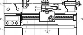
Thread cutting on a universal lathe is a common operation, especially in repair departments. The presence of a lead screw and a large feed range make it possible to cover basic needs without readjustments and special tools - a few threaded cutters are enough. The possibility of mechanized cutting with manual, machine taps, and lechers simplifies setup and speeds up the process while maintaining acceptable quality of fasteners.
Characteristics of metric thread
Before you begin the practical steps of thread cutting, you need to know its basic parameters and types. In the construction and renovation of housing, metric threads are used in most cases. What does it mean? According to the shape of the tooth, the thread can be metric, inch, rectangular, trapezoidal, etc.
Characteristics of metric thread
The thread we are interested in has the shape of a triangle, while the trapezoidal thread has the shape of a trapezoid. In addition, there is such a thing as a thread pitch, that is, the distance between its vertices: in the case of a metric thread, between the vertices of the thread triangle. And, of course, the characteristics of the thread include its diameter.
Let's consider the paragraph described above using the example of the M 12 thread, where the letter “M” indicates that the thread is metric, the number “12” determines the diameter of the thread. Where is the step size? The fact is that metric threads are divided into main and small, and if there is no other digital value after the number, it means the main thread. But if we have a thread M12 x 1.5 or M 12 x 1.25, then this means that the thread pitch is 1.5 and 1.25 mm, respectively. The pitch of the main thread M 12 is 1.75 mm.
Recommended drill diameters (in mm) for cutting metric threads
All these values for any type of thread can be found in reference books or on the pages of the corresponding websites on the Internet. For internal threads (nuts), there is another reference value - the diameter of the thread hole, which can be found there. For our M12 bolt, the internal diameter of the nut should be 12 mm minus the height of the tooth profile, that is, according to the reference books, 10.2 mm. For small thread M 12 x1.25, the diameter will be correspondingly smaller - 10.4 mm.
It is worth noting that something similar applies to a bolt or, as it is called in reference books, a rod. Again, for an M 12 thread, the diameter of the rod should be slightly less than 11.7 mm, but for an M 12 X 1.25 thread - 11.9 mm. If you do not comply with the dimensional tolerances for the threads for both the nut and the bolt, the thread will be of poor quality, weakened on one side, and on the other, if the tolerance is larger, it will simply break.
Accessories and tools for thread cutting
Don’t be afraid of the word “equipment” because, in essence, this is a device where the cutting tool is attached: taps and a die (cutter). The old name of the die is given in parentheses, but it can still be found. The equipment includes wrenches of a fairly simple design into which a tap is inserted for cutting threads in nuts and another type of device where a die for cutting bolt threads is attached.
Accessories and cutting tools for thread cutting
Taps, as well as dies, are made of high-carbon cast iron, so they are fragile and susceptible to heavy loads. Threading in nuts is mainly carried out by two taps: N 1 and N 2. The first has an incomplete thread for preliminary penetration, following which the second tap makes the cut.
Taps for thread cutting
As a result, the thread is full and of high quality, which means it will firmly hold the connection with the nut. Another type of tap is used, called a "machine" tap, which combines two tap numbers.
Die holder and die set
It would seem convenient, but this type of tap is long and inconvenient to use. Used for cutting long threads. As for the dies, they have one number.
Another type of equipment, without which the thread cutting process is almost impossible, is a medium-sized bench vise. What this is, probably, no one needs to explain. The only thing to remember is that the vice must be securely fastened.
Threading techniques
It is immediately necessary to make a reservation that the rod at the end and the threaded hole in the nut must be chamfered by any available method. Chamfers are necessary for precise entry without distortion of the cutting tool, that is, the tap and die. Next, we clamp the thread cutting object into the driver, clamp the rod or workpiece under the nut from a vice and proceed to thread cutting.
Thread cutting with a die
This is done without the use of excessive force and always with a lubricant, for which sulfo-fresol is ideal. However, if this is not available, you can use an emulsion (a solution of mineral oil in water) or simply vegetable oils.
By the way, if you decide to cut the thread of a bolt made of stainless steel or copper, there is no better lubricant than ordinary lard, which has been tested more than once in practice.
When cutting a thread, you need to feel the tap or die: if they begin to spring a little, that is, resist strongly, you need to turn them out and clear them of chips. If this is neglected, the cutting tool may simply crack and you will have to prepare a new rod or blank for the nut again.
And finally: if you do not have the opportunity to order blanks for a bolt or nut from a turner, purchase round timber (rolled metal in the form of a circle), which can have a diameter of five to 20 mm, and you don’t need more, because it is almost impossible to cut large-diameter threads by hand.
Technology for using taps and dies
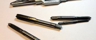
The tap is used when it is necessary to cut internal, mainly metric threads in holes of small diameter. It is a screw-shaped steel rod with grooves for chip removal located in the longitudinal direction. The tool consists of the following parts:
- Shank;
- Calibration part;
- Fence part.
To form a high-quality thread with a tap, 3 types of this turning tool are used sequentially, which can be distinguished by the number of marks placed on the shank:
The speed of work on a lathe with installed taps can be quite high. As an example, for aluminum, cast iron and bronze parts this technology indicator is about 6-22 m per minute, while for other materials it is from 5 to 12 m per minute.
The die is designed for cutting external threads. It is a flat cylindrical tool, in the center of which there is a hole with sharp edges and channels for removing chips. It looks like a nut. The calibrating part of the die is located in its middle, and the intake cone is located on each side. The tool on the lathe is fixed into a die holder - a special chuck in the tailstock quill. In order for the tool to enter the workpiece without effort, a chamfer is removed at the end of the workpiece, the height of which corresponds to the thread profile.
The dies can be split or solid. The diameter of the former is subject to adjustment within small limits, which makes it possible to restore the performance characteristics of the tool after wear. Solid versions are used to form high-precision threads. Alloy or carbon steel is used in production.
When using a die on a turning machine, the surface of the workpiece is subjected to preliminary turning to the required thread diameter, but taking into account the following tolerances:
- For threads 6-10 mm, the tolerance is 0.1-0.2 mm;
- For 11-18, the tolerance is 0.12 - 0.24 mm;
- For 20-30 mm, the tolerance is 0.14-0.28 mm.
The speed of thread cutting with a die installed in a lathe is adjusted in accordance with the workpiece material and directly affects the wear rate of the tool:
- For steel - 3-4 m per minute;
- For cast iron - 2-3 m per minute;
- For brass - 10-15 m per minute.
Application of Die Heads
When cutting threads on a screw-cutting lathe, the use of threading heads is used less frequently than the tools described above. The role of their working element is made by special combs of several types:
- prismatic;
- tangential;
- round;
- radial.
The first type of dies is used for cutting internal threads, the remaining three are used for external threads. A special feature of the tool is the automatic divergence of the working parts during the reverse stroke, which prevents their contact with the newly formed screw threads.
Threading heads on the machine are used mainly when high-precision work is required. When cutting threads on long screws and worms, the tool is mounted on the machine support. Round cutters are the most popular, as they are easy to maintain and have increased durability. For cutting internal threads on turret-type machines, exclusively prismatic dies with a special lead-in cone are used. The work is completed in one pass.
- To check the condition of the thread during its cutting on the machine, a thread template is used - a tool consisting of plates placed in a cassette on which there are notches. The thread pitch is indicated on the flat part of the template.
- For comprehensive control, thread gauges of the go-through type (with a full thread profile) and non-go-through type (with a shortened profile, to check the average diameter) are used. They must be handled with extreme care. Otherwise, scratches and nicks may form on the jagged surface.
- The diameters of the cut thread, as well as its pitch, are checked with a thread micrometer - a tool equipped with mounting holes in the spindle and heel, which act as fasteners for replaceable inserts. The micrometer is installed in the rack, after which it is adjusted according to the standard sample.
- Before checking the thread of a part with any of the specified tools, it must be cleaned of dirt and chips without removing it from the machine.
External thread cutting with a die
To cut external threads, you will need the following tools and materials: a die or pipe clamp, a die holder, a file, a vice, a caliper, and machine oil.
The most widespread are round dies (lerks). They are either solid or split. The diameters of solid round dies are standardized. This allows you to choose the appropriate option from a large range of sizes, for example, M10, M12, M14, M16.
A special feature of split dies is the ability to adjust the diameter of the thread being cut within 0.1…0.25 mm. However, they have reduced rigidity, which affects the accuracy of the resulting profile.
The die is installed in a die holder of a suitable size. After this, it is secured with screws. In the case of external pipe threads, die holders with a ratchet are often used. They provide convenience for working in hard-to-reach places, such as near a wall.
The thickness of the rod is chosen to be 0.1...0.25 mm less than the diameter of the external thread. For example, for M6 with a large pitch it is 5.80...5.90 mm; M8 – 7.80…7.90 mm; M10 – 9.75…9.85 mm. Measurements are taken using a caliper. The diameters of rods for cutting metric threads of average accuracy class 6g are presented in the table.
To ensure better insertion of the die, a chamfer is filed at the end of the rod. Its width should be 1 - 1.5 mm for M6 ... M18. The workpiece is lubricated with machine oil, which makes subsequent work easier and allows you to obtain a better surface.
The die is placed on the end of the rod so that its plane is perpendicular to the axis of the bolt being cut. Next, with slight pressure, rotate the die holder clockwise (if the thread is left-handed, then counterclockwise). When the die cuts into the rod by one or two threads, it should be turned back half a turn for better removal of chips. After this, they again make 1-2 turns along the thread and 0.5 in the opposite direction. Using this scheme, the bolt is cut to the required length.
The diameter of the external thread is checked with a regular nut or ring gauge. If necessary, the pitch is controlled with a thread gauge.
Application of cutters
When cutting threads with a cutter, the following types of this tool are used:
1. Round. Installed in the hole in the end of the holder. They belong to the shaped type of incisors. Used for internal and external processing of workpieces.
2. Rod. The heads are made of various shapes and sections, located on the rod. To increase the service life of the tool, some models have hard alloy brazing on the working edges.
3. Prismatic. Installation on the lathe is carried out using a dovetail holder. They are subject to more sharpening than round versions and are suitable for processing parts exclusively from the outside.
The outer threaded surface can be cut on a machine with both straight and bent versions of the tool mounted in a mandrel, and the inner one can be cut with curved and straight ones. High-speed steel is used in the manufacture of cutters. Detailed characteristics are standardized, and together with diagrams and drawings are indicated in GOST 18876-73.
The thread profile corresponds to the configuration of the tip of the cutter, which, in turn, can be rounded or have a chamfer. Depending on the material of the workpiece, the rake angle of the tool is selected (0-25 degrees). Thus, for hard and brittle parts this parameter is less than for those made of viscous and non-ferrous metals. There are detailed diagrams for choosing the cutting angle for most materials. Before cutting an internal thread on a machine, it is necessary to drill a hole or additionally bore it.
The rear lateral angles of the cutters are set to be the same on the right and left sides, and are selected in such a way that there is no friction between the surface of the tool and the groove formed by it. When the thread lead angle does not exceed 4°, the indicator is set in the region of 3–5°. Otherwise, the angle is set within 6 - 8 degrees.
When cutting threads on conical and cylindrical steel workpieces, cutters with carbide inserts T15K6, T30K4, T14K8, T15K6 are used. When working with cast iron parts, tools made of VKZM, V2K, VK6M, VK4 alloys are used.
Technology for using turning tools:
- The cutter is fixed in the tool holder, and the workpiece is fixed in the centers or chuck of the machine.
- The cutter moves along the axis of rotation of the workpiece, drawing a helical line. Both movements are strictly consistent with each other. In other words, during one revolution of the part, the cutter moves by the calculated pitch of the future thread.
- The support is driven by the spindle through the gearbox and lead screw. In this case, the gear ratio must be equal to the ratio of the pitch of the lead screw to the pitch of the thread being cut.
- The cutter is fed according to one of the following schemes: parallel to the generatrix of the thread (only the cutting edge is in contact), perpendicular to the axis of rotation of the workpiece (the entire profile is in contact).
- To form threads with large pitches on a machine, the workpiece is pre-processed with a slotted cutter. Its profile angle differs by 5-10° from the thread profile angle.
- Labor productivity when working with lathes is low, since a lot of time is spent reversing the cutter and setting it to size.
- The work requires increased attention and is performed exclusively by a highly qualified specialist.
Read also: Beading on a machine for beginners