from 250 to 350, but often higher depending on the quality of the workpiece
Material strength coefficient:
Steel, kg/mm
| Indicator value | |
| 50,1–60,1 | 1,61 |
| 60,1–70,3 | 1,27 |
| 70,3–80,1 | 1,1 |
| 80,3–90,1 | 0,87 |
| 90,3–100,1 | 0,73 |
| Cast iron, kg/mm | Indicator value |
| 140,1–160,3 | 1,50 |
| 160,1–180,1 | 1,21 |
| 180,1–200,3 | 1,1 |
| 200,3–220,3 | 0,83 |
Cutter life coefficient:
| Duration value, minutes | Index |
| 27–30 | 1,27 |
| 43–46 | 1,11 |
| 57–60 | 1,09 |
| 83–90 | 1,03 |
Cutting modes for turning and turning: formula tables, feed calculation and speed
Let's prepare for one of the most common operations. Let's consider the calculation of feed and cutting modes during turning. Its importance is difficult to overestimate, because if it is carried out correctly, it helps to make the technical process efficient, reduce production costs, and improve the quality of part surfaces. When it is optimally selected, it has the most positive effect on the operating life and integrity of the tools, which is especially important in the long term operation of machine tools while maintaining their dynamic and kinematic characteristics. And vice versa, if you choose it incorrectly and take the wrong initial indicators, you won’t have to talk about any high level of product performance, and you may even be faced with a defect.
Basic concepts of the turning process and cutting tools for turning
Home » Articles » Professionally about metalworking » Metal cuttingWe recommend purchasing:
Installations for automatic welding of longitudinal seams of shells - in stock!
High performance, convenience, ease of operation and reliability in operation.
Welding screens and protective curtains are in stock!
Radiation protection when welding and cutting. Big choice. Delivery throughout Russia!
When working on lathes, various cutting tools
: cutters, drills, countersinks, reamers, taps, dies, shaped tools, etc.
Turning cutters
- this is the most common tool intended for roughing, semi-finishing, finishing and fine (diamond) processing of the planes of external and internal cylindrical, conical and shaped surfaces, including threaded ones.
The classification of turning tools is based on the following characteristics:
- type of processing. Passing cutters for processing the outer cylindrical surface can be straight (Fig. 2.13, a; see also Fig. 2.3; 2.4; 2.5) and bent (Fig. 2.13, b). Bent cutters are widely used because of their versatility, which allows processing with transverse feed of not only cylindrical, but also end surfaces. Passing thrust cutters (Fig. 2.13, c; see also Fig. 4.20, c) have a leading angle φ = 90°; they are used when turning stepped rollers and when processing non-rigid parts. Scoring cutters (Fig. 2.13, d) are designed for processing end surfaces perpendicular to the axis of rotation of the part; these cutters operate with cross feed. Boring cutters (Fig. 2.13, d) are designed for machining holes on lathes; cutting-off (Fig. 2.13, f) - for cutting off workpieces or parts processed from a bar (for example, on bar lathes); thread-cutting (Fig. 2.13, g) - for cutting threads. Cutters for contour turning (Fig. 2.13, h) are used when processing bodies of rotation with a shaped generatrix on machines with copying devices and CNC. These cutters have increased auxiliary plan angles φ1. Shaped cutters (Fig. 2.13, i) are designed for processing parts with complex profiles on lathes and turrets, automatic and semi-automatic machines;
- nature of processing: roughing, finishing and cutters for fine turning;
- installation relative to the part: radial and tangential cutters;
- feed direction: right and left cutters;
- head design: straight, bent, curved and retracted incisors;
- cross-section: rectangular, square and round cutters (to unify the connecting dimensions of machine tool holders, cutter sections are standardized);
- design: solid, composite and prefabricated cutters;
- working part material: tool steels, hard alloys, ceramic materials, STM (diamond and CBN).
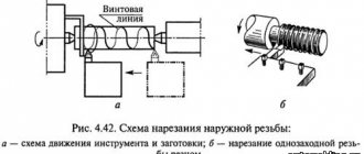
Cutting threads on lathes
in conditions of single or small-scale production, large threads are cut using thread cutters: rod cutters (Fig. 2.14, a, b and c), prismatic single-thread and multi-thread (Fig. 2.15, a and b), round (disc) single-thread and multi-thread (Fig. 2.15, c and d).
Rod high speed cutters
used for cutting cylindrical and conical external threads on screw-cutting lathes. When high-speed cutting of the same threads, cutters equipped with a carbide plate are used. Bent rod cutters are used for cutting internal threads (see Fig. 2.14, c).
When cutting threads on automatic and semi-automatic machines
Prismatic and round cutters are used. Prismatic cutters are used for making external threads, round ones - for external and internal threads. Thread cutting with single-thread cutters is carried out in several repeated passes. With the help of multi-thread cutters, the thread is made in one pass.
Round dies
(Fig. 2.16) are used both for manual work and on turret lathes and automatic machines for cutting fastening threads (mainly on bolts, screws and studs). The method of cutting threads with round dies is low-productive and does not provide accurate threads, but is still common in some factories. In mass and large-scale production, thread cutting with dies is replaced by more productive methods.
Cutting modes: what are they?
This is a whole complex of characteristics that determine the conditions for carrying out a turning operation. According to the technological routes, the processing of any element (especially complex in shape) is carried out in several transitions, each of which requires its own drawings, dimensions and tolerances, equipment and accessories. Having calculated and/or selected all these parameters once for the first workpiece, in the future you will be able to substitute them by default - when producing the second, fifth, hundredth part - and thus minimize the time for preparing the machine and simplify quality control, that is, optimize the production process .
The main indicators include depth, speed, feed, the list of additional ones includes the mass of the object, allowances, the frequency with which the spindle rotates, and, in principle, any characteristic that affects the result of processing. And it is important to choose those that will provide the best final accuracy, roughness and economic feasibility.
There are several ways to calculate cutting conditions when turning:
The first is quite accurate and, before the advent of powerful computer technology, was considered the most convenient. According to it, all calculations were carried out on the basis of the equipment’s passport data: engine power, spindle speed and other indicators were substituted into already verified empirical expressions and the required characteristics were obtained.
With the development of specialized software, the calculation task has been significantly simplified - all operations are performed by a machine, faster than a person and with a much lower probability of making mistakes.
When you don’t have a computer or formulas at hand, but you do have experience, you can determine the appropriate criteria based on normative and reference data from the tables. But for this it is necessary to take into account all changes in values, even the slightest, which is not always convenient in production conditions.
Features of determining cutting modes during turning
First of all, you need to select the processing depth, then the feed and speed. It is important to follow exactly this sequence - in order of increasing degree of impact on the instrument. First, those characteristics are calculated that can only minimally change the wear of the cutter, and finally those that affect the service life to the maximum.
Parameters should be determined for the maximum capabilities of the equipment, necessarily taking into account the dimensions, metal, and design of the tool.
An important point is to find a suitable roughness. Plus, it’s best to choose a blade for a specific material, because cast iron has one strength and hardness, while aluminum has a completely different one. Do not forget also that during the process the part heats up and the risk of its deformation increases.
The choice of cutting mode when turning on a lathe continues by establishing the type of processing. What will it be, rough or fine? The first is rough; tools made of hard steel and capable of withstanding the high intensity of the technical process are suitable for it. The second is thin, carried out at low speeds, with the removal of a minimal layer of metal.
The depth is determined by the number of passes during which the allowance is removed. Feed is the distance covered by the edge during rotation of the workpiece, and can be one of three types:
The speed largely depends on what kind of operation is being performed, for example, when facing it should be high.
Turning
Turning
is the main method of processing the surfaces of bodies of revolution.
The cutting process is carried out on lathes by rotating the workpiece (main movement) and moving the cutter (feed movement).
The feed movement is carried out:
- parallel to the axis of rotation of the workpiece (longitudinal);
- perpendicular to the axis of rotation of the workpiece (transverse);
- at an angle to the axis of rotation of the workpiece (inclined).
Schemes for processing workpiece surfaces by turning are presented in Fig. 19.2.
Using turning, the following operations are performed: turning - processing of external surfaces (Fig. 19.2.a); boring - processing of internal surfaces (Fig. 19.2.b); trimming – processing of end surfaces (Fig. 19.2.c); cutting - cutting the workpiece into pieces (Fig. 19.2.d); thread cutting - thread cutting (Fig. 19.2.e).
According to technological capabilities, turning is conventionally divided into: rough, semi-finish, fine, fine.
Rice. 19.2. Schemes for processing workpiece surfaces by turning
Cutters are used as cutting tools when turning.
The main principle of the classification of cutters is their technological purpose.
There are incisors:
- pass-through – for grinding external cylindrical and conical surfaces;
- boring - through and persistent - for boring blind and through holes;
- cutting machines - for cutting workpieces;
- threaded - for cutting external and internal threads;
- shaped – for processing shaped surfaces;
- slotted – for turning circular grooves;
- fillets - for grinding transition surfaces between shaft steps along the radius.
By the nature of processing - rough, semi-finish, finishing.
In the direction of the feed movement - right and left (right to left and left to right).
By design - whole, with a welded or soldered plate, with replaceable plates.
The setting for securing the workpiece depends on the type of machine, the type of surface being processed, the characteristics of the workpiece (), processing accuracy and other factors.
20. Electrophysical and electrochemical methods for processing workpiece surfaces. The essence of processing processes. Factors influencing the effectiveness of processing methods. Basic technical and economic characteristics of processes.
Characteristics of electrophysical and electrochemical processing methods
These methods are mainly intended for processing workpieces made of very strong, very tough, brittle and non-metallic materials.
These methods have the following advantages:
– there is no force effect of the tool on the workpiece (or very little and does not affect the total processing error);
– allow you to change the shape of the workpiece surface and influence the condition of the surface layer: hardening of the treated surface is not formed, the defective layer is insignificant; corrosion, strength and other operational characteristics of the surface are increased;
– it is possible to process very complex external and internal surfaces of workpieces.
EPHE processing methods are universal and ensure continuity of processes while simultaneously shaping the entire surface being processed. These methods are being implemented in various industries.
Electroerosive processing methods
These methods are based on the phenomenon of erosion of electrodes made of conductive materials when a pulsed electric current is passed between them.
The discharge between the electrodes occurs in a gaseous environment or when the interelectrode space is filled with a dielectric liquid - kerosene, mineral oil.
In the presence of a potential difference across the electrodes, ionization of the interelectrode space occurs. At a certain value of the potential difference, a conduction channel is formed through which electricity flows in the form of a pulsed spark or arc discharge.
On the surface of the workpiece, the temperature increases to 10000...12000 0C. Instantaneous melting and evaporation of an elementary volume of metal occurs and a hole is formed on the treated surface.
The removed metal solidifies in a dielectric liquid in the form of granules with a diameter of 0.01...0.005 mm.
With continuous supply of pulsed current to the electrodes, the erosion process continues until all the metal located between the electrodes at a distance at which electrical breakdown is possible (0.01...0.05 mm) at a given voltage is removed.
To continue the process, it is necessary to bring the electrodes closer to the specified distance. The electrodes are brought closer together automatically using tracking systems.
Electric spark machining
The diagram of electric spark processing is shown in Fig. 21.1.
Fig.21.1. Electric spark machine diagram:
1 – electrode-tool; 2 – bath; 3 – workpiece-electrode; 4 – dielectric liquid; 5 – insulator
In electric spark processing, pulsed spark discharges are used between
electrodes (workpiece (anode) – tool (cathode)).
The capacitor is charged through a resistor from a direct current source with a voltage of 100...200 V. When the voltage on electrodes 1 and 3 reaches the breakdown voltage, a channel is formed through which a spark discharge of the energy accumulated by the capacitor occurs.
Pulse duration 20…200 µs.
Processing accuracy up to 0.002 mm, 0.63...0.16 microns.
To ensure process continuity (clearance =const), the machines are equipped with a tracking system and an automatic tool feed system.
They produce through holes of any cross-sectional shape, blind holes and cavities, holes with curved axes, cut blanks from sheets, and perform flat, cylindrical and internal grinding.
They make stamps and molds, dies, and cutting tools.
Schemes of electric spark processing are presented in Fig. 21.2.
Rice. 21.2. Electric spark processing schemes:
a – stitching a hole with a curved axis; b – grinding the inner surface of the die
Electric spark processing is used to harden the surface layer of metal. A thin layer of metal or composite material is applied to the surface of the product. Such coatings increase hardness, wear resistance, heat resistance, erosion resistance, and so on.
Electropulse treatment
Electrical pulse processing uses electrical pulses of long duration (5...10 ms), resulting in an arc discharge.
High pulse powers from electronic generators provide high processing performance.
It is advisable to use electric pulse processing for the preliminary processing of dies, turbine blades, and shaped holes in parts made of corrosion-resistant and heat-resistant alloys.
The processing scheme is shown in Fig. 21.3.
Rice. 21.3. Electric pulse processing scheme:
1 – electric motor; 2 – pulsed DC generator; 3 – instrument-electrode; 4 – workpiece-electrode; 5 – bath.
Electrical contact processing.
Electrical contact processing is based on local heating of the workpiece at the point of contact with the electrode-tool and the removal of softened or molten metal from the processing zone mechanically: by relative movement of the workpiece or tool.
The heat source is pulsed arc discharges.
This type of processing is recommended for large parts made of carbon and alloy steels, cast iron, non-ferrous alloys, refractory and special alloys (Fig. 21.4).
Rice. 21.4. Scheme of electrical contact processing of a flat surface:
1 – workpiece being processed; 2 – electrode tool; 3 – transformer
This method is used for cleaning castings from fills, cutting off gating systems, stripping rolled products, and grinding corrosive parts made of difficult-to-cut alloys.
Electrochemical processing
Electrochemical processing is based on the laws of anodic dissolution of metals during electrolysis.
When an electric current passes through the electrolyte, chemical reactions occur on the surface of the workpiece, and the surface layer of the metal turns into a chemical compound.
Electrolysis products go into solution or are removed mechanically.
The performance of this method depends on the electrochemical properties of the electrolyte, the material being processed and the current density.
Electrochemical polishing.
Electrochemical polishing is carried out in a bath filled with electrolyte (solutions of acids and alkalis).
The workpiece being processed is connected to the cathode (Fig. 21.5). The cathode is a metal plate made of lead, copper, steel (sometimes the electrolyte is heated).
Rice. 21.5. Electrochemical polishing scheme:
1 – bath; 2 – workpiece being processed; 3 – electrode plate; 4 – electrolyte;
5 – microprotrusion; 6 – products of anodic dissolution
When voltage is applied, the process of dissolution of the workpiece metal begins (mainly on the protrusions of microroughnesses). As a result of selective dissolution, micro-irregularities are smoothed out, and the treated surface acquires a metallic sheen.
The electrical characteristics of parts are improved: the depth of microcracks is reduced, the surface layer is not deformed, hardening and thermal changes in the structure are eliminated, and corrosion resistance is increased.
Using this method, surfaces for galvanic coating are obtained, the working surfaces of cutting tools are finished, thin strips and foil are produced, parts are cleaned and decoratively finished.
Electrochemical sizing
Electrochemical dimensional processing is performed in a stream of electrolyte pumped under pressure through the interelectrode gap.
The electrolyte dissolves the salts formed on the surface of the workpiece - the anode - and removes them from the processing zone. The high productivity of the process lies in the fact that the entire surface of the workpiece is processed simultaneously.
Areas that do not require treatment are isolated. The tool is given a shape opposite to the shape of the surface being processed. Shaping occurs using the copying method (Fig. 21.6).
Rice. 21.6. Scheme of electrochemical dimensional processing:
1 – tool – cathode; 2 – workpiece – anode
Machining accuracy increases as the working gap decreases. To monitor it, highly sensitive elements are used that are built into the tracking system.
This method is recommended for processing workpieces made of high-strength steels, carbide and difficult-to-cut materials. It is also possible to process thin-walled parts with high precision and quality of the machined surface (there is no tool pressure on the workpiece).
Combined processing methods
Electroabrasive and electrodiamond processing.
For these types of processing, the tool is a grinding wheel made of an abrasive material with an electrically conductive bond (bakelite bond with graphite filler).
There is a gap between the anode - the workpiece and the cathode - grinding wheel, into which the electrolyte is supplied. Anodic dissolution products are removed with abrasive grains; the grinding wheel has a rotational movement, and the workpiece has a feed movement, which correspond to the mechanical grinding process (Fig. 21.7).
Rice. 21.7. electric abrasive grinding scheme:
1 – workpiece; 2 – abrasive grains; 3 – bunch of grinding wheel.
The introduction of ultrasonic vibrations into the cutting zone increases productivity by 2...2.5 times while improving surface quality. These methods are used for finishing workpieces made of difficult-to-cut materials, as well as non-rigid workpieces, since the cutting forces are insignificant.
Anodic mechanical treatment
Anodic-mechanical processing is based on a combination of electrothermal and electromechanical processes and occupies an intermediate place between electroerosive and electrochemical methods.
The workpiece is connected to the anode, and the tool is connected to the cathode. Metal discs, cylinders, tapes, and wire are used as tools.
The treatment is carried out in an electrolyte environment (an aqueous solution of liquid sodium glass).
Working movements, as in machining by cutting.
The electrolyte is fed into the processing zone through a nozzle (Fig. 21.8).
Rice. 21.8. Scheme of anodic-mechanical treatment of a flat surface.
When a direct electric current is passed through an electrolyte solution, a process of anodic dissolution occurs, as in electrochemical treatment.
When the tool comes into contact with micro-irregularities of the workpiece, electrical erosion occurs, which is inherent in electric spark machining. The metal of the workpiece at the point of contact with the tool heats up and liquefies. The products of electrical erosion and anodic dissolution are removed by relative movements of the tool and the workpiece.
This method is used to process workpieces made of high-strength and difficult-to-process alloys and viscous materials.
Using this method, workpieces are cut into pieces, grooves and slits are cut, the surfaces of bodies of rotation are processed, flat surfaces and surfaces shaped like bodies of rotation are polished, surfaces are polished, and cutting tools are sharpened.
Beam processing methods
Electron beam processing
– is based on the conversion of the kinetic energy of a directed electron beam into thermal energy. The high energy density of the focused electron beam allows the workpiece to be processed by heating, melting and evaporating the material from a local area.
The scheme of electron beam processing is shown in Fig. 21.9.
An electron beam is formed due to the emission of electrons from a cathode heated in a vacuum. It focuses on the workpiece using electrostatic and electromagnetic lenses.
During dimensional processing, the installation operates in pulse mode, which ensures local heating of the workpiece.
The electron beam method is effective when processing holes with a diameter of 1...0.010 mm, when cutting grooves, cutting workpieces, making thin films and meshes from foil, making workpieces from difficult-to-cut metals and alloys, ceramics, quartz, and semiconductor materials.
Rice. 21.9. Installation diagram for electron beam welding: 1 – electron gun cathode; 2 – electrode; 3 – anode; 4 and 5 – deflection magnetic system; 6 – workpiece
Laser processing
– based on the thermal effect of a high-energy light beam on the surface of the workpiece. The source of light radiation is a laser – an optical quantum generator.
The energy of the light beam is not great, 20...100 J, but it is released in millionths of a second and is concentrated in a beam with a diameter of 0.01 mm. Therefore, the temperature in the contact zone is 6000...8000 0C.
The metal layer instantly melts and evaporates. This method is used to sew holes, cut workpieces, and cut grooves in workpieces made of any materials (tantalum, tungsten, molybdenum foil). Also, using this method, you can carry out contouring along a complex perimeter.
Plasma treatment
The essence of the treatment is that plasma is directed onto the surface being treated.
A plasma jet is a directed flow of partially or fully ionized gas having a temperature of 10,000...20,000 0C. Plasma is produced in plasma torches by passing gas through a compressed arc column. Nitrogen, argon, hydrogen, helium, air and their mixtures are used as plasma-forming gases.
Using this method, holes are sewn, blanks are cut out of sheet material, and blanks made of any materials are turned.
When making holes and cutting, the head is installed perpendicular to the surface of the workpiece, when planing and turning - at an angle of 40...60 0.
Plasma spraying.
This type of processing is carried out in order to obtain specified dimensions.
Powdered structural material and inert gas under pressure are supplied into the plasmatron chamber.
Under the action of an arc discharge, the structural material melts and turns into a plasma state; The plasma jet is compressed in the plasmatron by gas. Coming out of the nozzle, the jet is directed towards the workpiece being processed.
Characteristics of cutting conditions
Before we consider all the main parameters in detail, let’s say a few more words about calculation methods. More precisely, about how they moved from graphics to analytics and computerization.
As production improved, even the most detailed tables turned out to be less and less convenient: columns, columns, ratios - it took a huge amount of time to study this and find the right value. And this despite the fact that the main indicators are interconnected, and a decrease/increase in one of them provoked changes in the others.
Having established such an obvious dependence, engineers began to use the analytical method, that is, they thought through empirical formulas, and began to substitute spindle speed, power of the power unit and feed into them and find the necessary characteristics. Well, the development of computers and the emergence of computing software seriously simplified the task and protected the final results from human errors.
Scheme for calculating the cutting mode on a lathe
The procedure is as follows:
Now we move on to consider specific characteristics that play an important role, and to ways of finding or changing them in practice.
Depth of cut when turning on a machine
A key indicator for ensuring the quality of a part, showing how much material needs to be removed in one pass. The total number of the latter is calculated taking into account the following ratio of allowances:
The shape of the workpiece and what kind of operation is being performed also play a role. For example, when facing, the parameter in question is equated to the double radius of the object, and for cylindrical parts it is found as follows:
If the product is flat, the usual linear length values are used - 2, 1-2 and up to 1 mm, respectively. There is also a dependence on the supported accuracy class: the lower it is, the more approaches you need to make to get the result.
How to determine feed when turning
In fact, it represents the distance that the cutter moves in one revolution made by the workpiece. It is highest during roughing, least during finishing, when you should act carefully, and the quality of roughness also comes into play. In general, it is done as much as possible (for the operation) taking into account limiting factors, including:
When milling, preference is given to the “tooth” option, when cleaning holes - recommended for the current tool, for training purposes - the most common one, that is, 0.05-0.5 rpm.
The formula for calculating feed during turning, connecting all its types, looks like this:
n – cutter rotation frequency,
To simplify the calculations, you can take the data from here:
Diameter, blanks, mm
Feed, mm/rev, with selected cutting depth, mm
Source
Fine processing of shafts and surfaces
Methods for fine processing of shafts
To achieve high accuracy and low roughness of the outer cylindrical surfaces of the shafts, various types of finishing processing are used. The main methods of finishing processing of shafts: grinding, fine (diamond) turning, polishing, superfinishing, lapping, roller rolling, etc. The processing method is chosen based on the requirements for the accuracy and roughness of the processed surfaces, as well as depending on the nature of the part.
Grinding
- the most common method of finishing the outer surfaces of shafts. Usually, by means of grinding, 6...7th accuracy quality and 8th class of surface roughness (Ra ? 0.63 μm) are obtained.
Fine (diamond) turning
They are used mainly for processing shafts made of non-ferrous metals and alloys (bronze, brass, aluminum, etc.), less often for processing shafts made of cast iron and steel. Grinding non-ferrous alloys is more difficult than grinding steel and cast iron due to clogging of the grinding wheel.
Fine turning is carried out with diamond cutters or cutters equipped with hard alloys (for example, T30K4). Processing is carried out at low cutting depth (t = 0.05...0.3 mm) and feed (S = 0.13...0.15 mm/rev) and high cutting speed (v = 100...1000 m/min).
Diamond turning machines must be high-speed (rotation speed up to 8000 min-1) and have increased accuracy and rigidity.
In terms of productivity, fine (diamond) turning is somewhat superior to grinding.
Super finishing
- final processing of pre-polished surfaces (usually external cylindrical ones) using fine-grained abrasive or diamond whetstones, making a complex movement to obtain a high quality surface. Superfinishing bars are made from grinding and micropowders.
Polishing
- processing of parts using a fine-grained abrasive (polishing) paste applied to an elastic polishing wheel, which is made of felt, leather and canvas. Powders of chromium oxide, crocus (iron oxide), Vienna lime, sometimes corundum and silicon carbide are used as abrasives. The peripheral speed of rotation of the wheel when polishing parts made of steel and cast iron is 30…35 m/s. The part is pressed against the circle with a force equal to 20...50 N.
Polishing is usually used for decorative finishing of parts, as well as as a preparatory operation before nickel plating, chrome plating and other galvanic operations. The surface roughness after polishing corresponds to grade 7...12.
Lapping
- the process of surface treatment by lapping, the working surface of which is coated with fine-grained abrasive powder (grain size 3...20 microns), in the presence of lubricant or special paste. The workpiece rotates and makes complex movements. Lappings are made of cast iron, bronze or copper.
Caricature
— introduction of abrasive grains into the working surface of the lap, which play the role of cutting elements. Corundum, synthetic diamonds, silicon carbide, chromium oxide, iron oxide, etc. are used as abrasive powder. Pastes consist of abrasive powders and chemically active substances. For example, the composition of the GOI (State Optical Institute) paste includes an abrasive in the form of chromium oxide and a binder - oleic and stearic acids. Pastes speed up the lapping process, since chemically active substances promote oxidation of the metal being processed, the products of which are then removed by abrasive grains.
Fine surface treatment methods
Using finishing cutting, the following parts are obtained:
· either with the required accuracy of the size and shape of surfaces (shape deviation is 0.05 -0.025 microns for precision parts and 1 - 2 microns for parts of fine mechanical engineering and instrument making);
· either with high quality and surface roughness from Ra
= 0.32 – 0.16 µm to
Rz
= 0.05 – 0.025 µm;
· or simultaneously with high accuracy of dimensions and shape of surfaces with the required roughness and quality of the surface layer.
Fine machining includes fine turning, fine grinding, fine boring and fine diamond turning.
Fine turning
used instead of grinding. This process occurs at high cutting speeds, small depths of cut and feeds. Cutters with wide cutting blades made of hard alloys or superhard materials are used.
Fine grinding
produced with a fine-grained wheel at a very small depth of cut. Grinding is accompanied by an abundant supply of coolant. A special role is played by the rigidity of machines capable of ensuring vibration-free operation.
Fine grinding ensures the shape of the original workpiece (deviation of the shape of cylindrical surfaces does not exceed 5 μm) and obtains surfaces with roughness Ra
= 0.160 – 0.010 µm. Fine grinding is the final stage of processing the workpiece on a grinding machine. To perform it, machines of high rigidity and precision are used - classes B, A and C. The peculiarity of fine grinding is the need for careful preparation of the machine and tool for work.
Fine diamond turning
used for processing non-ferrous metals and alloys, plastics and other non-metallic materials. Due to their very high durability, diamond cutters are able to work for a long time without adjustment and provide high precision processing. Fine diamond turning requires high-speed machines of high rigidity and accuracy, as well as high-quality pre-processing of workpieces.
Fine boring
often used instead of grinding, especially in cases where thin-walled workpieces are made of viscous non-ferrous alloys or steel. The use of fine boring is also justified in cases where it is necessary to perform precise machining of blind holes or when the presence of abrasive grains in the pores of the machined surface is unacceptable, which is typical for grinding.
What it is
Cutting mode most often refers to characteristics that are found by calculation. These are depth, speed and serve. These values are very important. Without them, it is simply impossible to qualitatively turn any part.
When calculating operating modes, other characteristics of the work manipulations performed are also taken into account:
If necessary, many other characteristics of those elements that affect the processing of parts are taken into account.
Characteristics of operating modes
The calculation of the cutting operation is carried out using special reference and regulatory documents, of which there are quite a few at the moment. It is necessary to carefully study the tables presented and select the appropriate values in them. A correctly performed calculation guarantees the high efficiency of the applied part processing mode and ensures the achievement of the best result.
But this method of calculation is not always successful, especially in production conditions, when it is inappropriate to spend a lot of time studying tables with a huge number of values. It has been established that all values of cutting modes are interrelated. If you change one value, it is natural that all other processing characteristics will become different.
Therefore, very often specialists prefer to use calculation or analytical methods for determining cutting conditions. Special empirical formulas are used to determine all the necessary standards. In order for the calculations using this method to be absolutely accurate, you need to know the following parameters of the lathe:
In modern industries, special software is used to perform such calculations. The specialist just needs to enter the known data, after which the computer will produce the calculated values. The use of calculation programs greatly facilitates the work of specialists and makes production more efficient.
Calculation scheme
Before performing calculations for a cutting operation, it is necessary to determine what type of cutting tool will be used in this case. When turning or abrasively machining fragile materials, equipment with minimal performance is selected. It should be remembered that during operation the part usually gets quite hot. If the processing speed is very high, it may become deformed, rendering it unusable.
It is necessary to take into account what kind of processing will be carried out - finishing or roughing. In the first case, operating parameters are selected that will ensure maximum accuracy. Experts also pay attention to the thickness of the cut layer. Depending on this characteristic, the number of penetrations is selected to perform trimming using special equipment.
Depth
Depth is one of the most important parameters to ensure the quality of manufactured workpieces. It determines the thickness of the cut layer in one pass. When trimming the end, the diameter of the part is taken as the depth.
The number of passes is taken into account, which is determined by processing allowances:
To determine the cutting depth of cylindrical workpieces, the following formula is used:
k=(Dd)/2 , where k is the cutting depth, D is the initial diameter, d is the resulting diameter.
When determining cutting conditions when working with flat parts, length is used instead of diameters. It is generally accepted that during roughing the depth should be more than 2 mm, semi-finishing - 1-2 mm, finishing - less than 1 mm. This parameter depends on the quality requirements of the parts. The lower the accuracy class, the more passes must be performed to achieve the required properties of the products.
Innings
Feed refers to the amount of movement of the cutter per revolution of the workpiece. When performing roughing, this parameter can have the maximum possible values. At the final stage of work, the feed value is determined taking into account the roughness quality. This characteristic depends on the cutting depth and dimensions of the workpiece. The smaller the size, the lower it is. If the thickness of the cut layer is large, the minimum feed parameters are selected.
To make the work easier for specialists, special tables have been developed. Feed values are indicated there under different cutting conditions. To make accurate calculations, it is sometimes necessary to know the size of the cutter holder.
If cutting is performed with significant impact loads, the values from the table must be multiplied by a factor of 0.85. When working with heat-resistant structural steel, the feed should not exceed 1 mm/rev.
Speed
Cutting speed is one of the most important indicators, which is determined at the calculation stage before performing the main work. Its values depend on the operations performed. Typically, end cutting occurs at the highest possible speed. Drilling or turning have completely different requirements for this operating parameter. Therefore, to perform the assigned tasks efficiently, you need to know the following:
In traditional turning, the speed is determined by multiplying the diameter of the workpiece by its number of revolutions per minute and by π. The resulting value must be divided by 1000. Also, the cutting speed can be determined using standard tables for cutting modes.
Checking selected performance characteristics
Once the depth, feed and speed are determined, they need to be checked. The obtained operating parameters should not exceed the standard values indicated in the passport of the operating lathe.
It is imperative to determine the power of the equipment. To do this, the cutting force is multiplied by its speed and divided by 1000. The resulting value is compared with what is indicated in the machine passport. If the parameters calculated by the formulas are larger, it is necessary to adjust the depth, feed and speed to avoid damage to equipment and tools.
Rating of the best turning tools for 2022
The product review was compiled based on customer reviews of online tool stores and the Yandex Market platform. There are three categories: according to cost - cheap, expensive, sets consisting of 6 or 12 tools.
Cheap (from 68 to 265 rubles)
5th place Boring through 25x25 VK8
Price: 265 rubles.
Manufacturer: Russian brand “INIGS”.
Type – boring through. Specifications (mm):
- holder 25*25;
- length 200;
- weight 980 g.
Alloy – VK8 (cobalt 8%, tungsten 92%). GOST standards – 18882-73.
Used when boring through holes (conical, cylindrical). Can be used on objects made of alloy steel, stainless steel (of varying hardness), cast iron, non-ferrous alloys, plastic, titanium.
Boring through 25x25 VK8
Advantages:
- wide application on different materials;
- durable composition;
- standard parameters.
Flaws:
- not identified.
4th place Straight through 20x12 T5K10
Price: 68 rubles.
Manufacturer – Kanashsky IZ (Russia).
Type – straight through.
Parameters (mm):
- length – 120;
- holder section – 20*12;
- weight – 0.2 kg.
Alloy – T5K10. Used for chamfering, turning parts from non-rigid materials, stepped shafts, protruding parts.
Straight through 20x12 T5K10
Advantages:
- easy to find in stores;
- performs many functions;
- compliance with GOST standards.
Flaws:
- not identified.
3rd place Trimming bent 16x10x100 T5K10 2112-0086
Cost: 102 rubles.
(Russia).
Type – bent scoring with soldered plates. Right feed direction.
Parameters (mm):
- length – 100;
- width – 16;
- weight – 400 g.
Materials: plate – T5K10, holder – steel 45. Compliance with GOST – 2112-0086.
Functionality: ledges (at right, sharp angles), turning along the axis, processing of end parts.
Bent trim 16x10x100 T5K10 2112-0086
Advantages:
- compliance with the requirements;
- universal alloy;
- wide application;
- you can work at higher modes.
Flaws:
- not identified.
2nd place Bent 25x16x140 T5K10 2102-0005
Price: 235 rubles.
Manufacturer – Russia.
Type – bent through.
Specifications (mm):
- length – 140;
- width – 16;
- weight – 400 g.
T5K10 alloy is used. The product is made according to GOST parameters.
Functions: roughing and finishing, cutting ends and sides, stepped parts.
Bent 25x16x140 T5K10 2102-0005
Advantages:
- hard alloy;
- compliance with GOST;
- performs many functions;
- easy to find on sale.
Flaws:
- not identified.
1 place Straight through 16x10x100 T5K10 2100-0401
Cost: 99 rubles.
Product from a Russian manufacturer. Refers to the type of straight line.
Parameters (mm):
- length (L) – 100;
- width – 20;
- weight – 380 g.
Material – T5K10. Manufactured according to GOST 18878-73, designated 2100-0013.
It is used when processing various shapes and materials.
Straight through 16x10x100 T5K10 2100-0401
Advantages:
- universal application;
- quality composition;
- Russian manufacturer;
- low price.
Flaws:
- not identified.
Expensive
They differ in structure - they have threaded plates, functionality - processing of wooden and metal objects.
5th place HSS Line Profi 16 mm Narex 819316
Cost: 7,230 rubles.
(Czech Republic).
Purpose – processing of wooden blanks. Consists of a handle (elongated shape, material – light natural beech), a brass cap. There is a steel blade and a hard alloy roller.
Dimensions (mm):
- total length – 395;
- plate diameter – 16;
- blade – 150;
- handle – 315.
Product weight (packed) – 360 g.
The product is made of HSS steel with hardness HRC 64 (blade), natural beech (handle). The surface is ground and polished.
HSS Line Profi 16 mm Narex 819316
Advantages:
- high quality steel;
- blade strength;
- for wooden elements;
- comfortable handle shape made of natural wood.
Flaws:
- high price.
4th place Cutting groove for replaceable inserts MGEHR1010-1.5
Price: 903 rubles.
Manufacturer – . Designed for processing metal elements. Features: Replaceable plates (MGMN150).
Dimensions (mm):
- length – 100;
- width – 10;
- height – 10.
Weight – 100 g. Made in right-hand version (R).
Functions: processing of external grooves, cutting of the required size.
Cutting groove for replaceable inserts MGEHR1010-1.5
Advantages:
- replaceable plates;
- GOST standards;
- available for sale.
Flaws:
- plates must be purchased separately.
3rd place Cutting tool for replaceable inserts ZQ2525R-4
Cost: 1,283 rubles.
The product is manufactured.
Purpose: cutting grooves, cutting metal elements. Features: replaceable inserts with one cutting side, rigid structure, low deformation.
Parameters (cm):
- length – 15;
- width – 2.5;
- height – 2.5;
- plate width – 0.4.
Weight – 720 g. Depth of the resulting groove – 2 cm.
Correct execution of the product. Plate type – SP400.
Cutting machine for replaceable inserts ZQ2525R-4
Advantages:
- processing of metal parts;
- high-quality element designs;
- long-term use;
- one functional side of the plate.
Flaws:
- not identified.
2nd place For replacement inserts for external turning 25mm WWLNR2525M08
Price: 1,283 rubles.
.
Features: W-trigonal shape of the plate, angle – 95⁰, fastening W-clamp with a wedge clamp on a pin.
Dimensions (cm):
- total length – 15;
- holder section – 2.5*2.5;
- width – 7.
Weight – 850 g.
Product brand – WWLNR, plate – WN-0804.
Functions: chamfering, trimming, external turning.
For indexable inserts for external turning 25mm WWLNR2525M08
Advantages:
- reliable fastening;
- plate shape;
- functional;
- durability of materials.
Flaws:
- plates are not included.
1 place Thrust and contour pass-through for replaceable inserts MDJNR1616H11
Cost: 1,074 rubles.
The product is manufactured (Russia).
It differs: fastening system – M (combined clamp), main angle 93⁰, right-hand feeding direction.
Characteristics (cm):
- length – 10;
- width, height – 1.6;
- cutter length (working part) – 3.15.
Weight – 230 g. Suitable plates DN-1104.
Functions: contouring, longitudinal, transverse turning.
Pass-through thrust and contour for replaceable inserts MDJNR1616H11
Advantages:
- performs many tasks;
- suitable for roughing;
- combined fastening.
Flaws:
- not found.
Sets
They consist of several items (from 5 to 12 pieces) and have different functionality (working on metal, wood).
5th place Woodworking set Enkor 10430, 8 items
Price: 7,440 rubles.
Manufactured (Russia, Voronezh) in China.
The set consists of 8 tools. Sold in a light-colored wooden box with a hinged lid. Contents - instructions for use.
The tools consist of a blade, a handle, and a ferrule.
Materials: blades - high-speed steel, handle - wood with a multi-layer cherry varnish coating.
Case parameters (cm):
- length – 44.5;
- width – 31.5;
- height – 4.5.
The weight of the box with tools is 2.6 kg.
Functionality: roughing, cutting off excess parts, facing, turning rounded shapes.
Woodworking set Enkor 10430, 8 items
Advantages:
- the number of different blade shapes in one set;
- comfortable handle;
- easy to store and transport;
- suitable as a gift for a beginner;
- attractive tool design.
Flaws:
- sharpening required.
4th place Set METALMASTER 18978, 5 pieces, wood
Cost: 11,499 rubles.
Manufacturer – (Russia).
Consists of 5 tools, wooden box with lid. There is a company logo sticker on the top of the lid. Bottom sides - the inscription “Made in Russia”, compliance with GOST.
Specifications (mm):
- blade length – 150;
- handle length – 330;
- blade width – 24.
Material: blade – steel R6M5 (hardness HRC 64), wooden handle – birch.
The set includes cutters:
- Cut-off.
- Right oblique.
- Rip-off.
- Section 30 mm.
- Section 12 mm.
The tools are manufactured according to GOST 19265-73 standards and are intended for working with wooden products.
Set METALMASTER 18978, 5 pieces, wood
Advantages:
- quality steel;
- high hardness;
- comfortable handle;
- popular assortment;
- beautiful wooden case.
Flaws:
- only 5 items.
3rd place Set Proma (25330808), 11 pcs
Price: 4.020-4.455 rubles.
Manufactured (Czech Republic).
Consists of 11 items, with a soldered VK8 plate. Suitable for Proma SM-300,350 lathes, mini-machines from other companies.
Dimensions (cm):
- length – 8 (9 pieces), 12.5 (2 pieces);
- cross section – 0.8*0.8.
Weight (with packaging) – 0.600 kg.
Packaging – cardboard box (length – 16 cm, width – 6 cm). Each tool is packaged in an individual zip bag.
Equipment:
- Passing straight.
- Passing bent right.
- Boring passage.
- Boring persistent.
- Shaped.
- Threaded (external thread).
- Grooved.
- Passing bent left.
- Cut-off.
- Tortsovy.
Functions: longitudinal grinding, trimming, cutting, external threading, chamfering.
Proma set (25330808), 11 pcs.
Advantages:
- a large set of items;
- performs basic types of work on the machine;
- simple packaging;
- affordable price.
Flaws:
- needs sharpening;
- no internal thread cutting.
2nd place Cutters for lathe FD 150/E, 6 x 6 x 60 mm, 6 pcs. Proxxon (24524)
Cost: 6,072 rubles.
Manufacturer: German.
It is used when processing metal and plastic elements.
Consists of 6 tools, packaged in a wooden box with a retractable lid.
Product parameters (cm):
- length – 6;
- cross section – 0.6*0.6.
Material: cobalt high-speed steel (HSS), case-hardened.
Suitable for the tool holder of the FD 150/E lathe.
Cutters for lathe FD 150/E, 6 x 6 x 60 mm, 6 pcs. Proxxon (24524)
Advantages:
- common types of incisors;
- quality work;
- durability of products;
- convenient packaging.
Flaws:
- recommended only for a specific machine.
1 piece Set of turning tools for metal 10x10 VK8 12 pcs
Price: 5.627 rubles.
The set consists of 12 pieces with soldered plates and a wooden box. retractable cover.
Equipment:
- Passage bent.
- Passing straight.
- Grooved internal.
- Left trim.
- Cut-off.
- Passing persistent straight double-sided right.
- Passing persistent straight double-sided left.
- Boring (blind holes).
- Boring (through holes).
- Trimming.
- Passing bent left.
- Threaded (external thread).
Material – hard alloy VK8.
Compliance with GOST standards. Suitable for household machines.
Weight (packed) – 1.3 kg.
Set of turning tools for metal 10x10 VK8 12pcs
Advantages:
- a large number of tools;
- high-quality alloy;
- multifunctional;
- convenient storage, carrying;
- Suitable for most machine models.
Flaws:
- not identified.
Which cutting tool to use
The production of parts on such machines is carried out using special turning tools. They must provide the following:
Turning cutters are classified according to different parameters. Depending on the type of work performed, they can be cutting, passing, shaped, scoring, etc. Cutters are made from various materials - diamonds, tungsten, titanium-tungsten and others. Depending on the design, these tools can be one-piece, prefabricated or combined.
The choice of a specific type of tool is carried out taking into account the modes of the work operations being carried out, the hardness of the workpiece, the geometric parameters of the cutting part and other characteristics.
Related video: Metal turning
Source
Features of the design of a metal turning cutter
The design of the element consists of a cutter holder, thanks to which the tool is fixed on the machine, and a working head, which directly processes the surface of the workpiece. The holder may have a square or rectangular cross-section. The working part of the tool is formed from several adjacent planes and cutting edges. Their sharpening angle depends on the characteristics of the material being processed and the type of processing.
To achieve the specified parameters of the part, the cutter and workpiece fixed in the machine move relative to each other
The working head can be solid or with welded or soldered plates. New are metal cutters for lathes with replaceable inserts. The first option is presented as a one-piece element with a holder. Such a tool can be made of special high-carbon tool or high-speed steel. But such cutters are used extremely rarely.
Mostly for metalworking on a lathe, cutters with welded or soldered plates are used. The tool is made from high-speed steel or a hard alloy containing metals: titanium, tungsten and tantalum. It is distinguished by its high strength and pricing policy. This turning tool can be used for processing products made of non-ferrous metals, cast iron, any steel and non-metallic materials.
Important! When working with carbide inserts, you should adhere to safety rules, since the products are very fragile.
Very often, when processing materials, turning cutters with replaceable inserts are used. Unlike the previous version, the plate is attached to the head mechanically using special clamps or screws. The tool is convenient for further use if the plate is made of mineral ceramics, which significantly increases the cost of a cutter with replaceable plates.
A variety of metal turning cutters with replaceable inserts
The working part for a lathe cutter can be made of hard alloy (tantalum-tungsten-titanium, titanium-tungsten, tungsten), high-speed steel (high or normal efficiency), high-quality carbon steel. Cutters can be used for such types of lathes as planing, turning, slotting, turret and special.
What it is
Cutting mode most often refers to characteristics that are found by calculation. These are depth, speed and serve. These values are very important. Without them, it is simply impossible to qualitatively turn any part.
When calculating operating modes, other characteristics of the work manipulations performed are also taken into account:
If necessary, many other characteristics of those elements that affect the processing of parts are taken into account.
Calculation scheme
Before performing calculations for a cutting operation, it is necessary to determine what type of cutting tool will be used in this case. When turning or abrasively machining fragile materials, equipment with minimal performance is selected. It should be remembered that during operation the part usually gets quite hot. If the processing speed is very high, it may become deformed, rendering it unusable.
Metal cutting process
It is necessary to take into account what kind of processing will be carried out - finishing or roughing. In the first case, operating parameters are selected that will ensure maximum accuracy. Experts also pay attention to the thickness of the cut layer. Depending on this characteristic, the number of penetrations is selected to perform trimming using special equipment.
Depth
Depth is one of the most important parameters to ensure the quality of manufactured workpieces. It determines the thickness of the cut layer in one pass. When trimming the end, the diameter of the part is taken as the depth.
The number of passes is taken into account, which is determined by processing allowances:
Changing the processed diameter
To determine the cutting depth of cylindrical workpieces, the following formula is used:
k=(Dd)/2 , where k is the cutting depth, D is the initial diameter, d is the resulting diameter.
When determining cutting conditions when working with flat parts, length is used instead of diameters. It is generally accepted that during roughing the depth should be more than 2 mm, semi-finishing - 1-2 mm, finishing - less than 1 mm. This parameter depends on the quality requirements of the parts. The lower the accuracy class, the more passes must be performed to achieve the required properties of the products.
Metal roughing scheme
Innings
An example of constructing a cutter trajectory
Feed refers to the amount of movement of the cutter per revolution of the workpiece. When performing roughing, this parameter can have the maximum possible values. At the final stage of work, the feed value is determined taking into account the roughness quality. This characteristic depends on the cutting depth and dimensions of the workpiece. The smaller the size, the lower it is. If the thickness of the cut layer is large, the minimum feed parameters are selected.
To make the work easier for specialists, special tables have been developed. Feed values are indicated there under different cutting conditions. To make accurate calculations, it is sometimes necessary to know the size of the cutter holder.
If cutting is performed with significant impact loads, the values from the table must be multiplied by a factor of 0.85. When working with heat-resistant structural steel, the feed should not exceed 1 mm/rev.
Feeds for rough external turning
Speed
Cutting speed is one of the most important indicators, which is determined at the calculation stage before performing the main work. Its values depend on the operations performed. Typically, end cutting occurs at the highest possible speed. Drilling or turning have completely different requirements for this operating parameter. Therefore, to perform the assigned tasks efficiently, you need to know the following:
Table for calculating cutting conditions
In traditional turning, the speed is determined by multiplying the diameter of the workpiece by its number of revolutions per minute and by π. The resulting value must be divided by 1000. Also, the cutting speed can be determined using standard tables for cutting modes.
Checking selected performance characteristics
Once the depth, feed and speed are determined, they need to be checked. The obtained operating parameters should not exceed the standard values indicated in the passport of the operating lathe.
It is imperative to determine the power of the equipment. To do this, the cutting force is multiplied by its speed and divided by 1000. The resulting value is compared with what is indicated in the machine passport. If the parameters calculated by the formulas are larger, it is necessary to adjust the depth, feed and speed to avoid damage to equipment and tools.
Selecting cutter material for turning
Metalworking – Mechanical – With chip removal – Metal blade tools – TurningTurning (boring) is a method of processing a workpiece with a metal single-edged tool.
Technological parameters:
- t = from 0.03-0.05 to 7-8 mm, sometimes t = 0.002-0.006 mm;
- S = 0.05-0.1 to 1.5-2 mm/rev; (see tables No. 1-5)
- V = from 1-2 to 150-1000 m/min; (see tables No. 6-8)
- cutting forces Pz = from 10-15 to 800-900 kgf.
Turning (boring) is carried out on machines :
- Lathes
- Revolver
- Boring
- Carousel
- Automatic and semi-automatic lathes (single- and multi-spindle) with horizontal and vertical spindles
- Multi-cutting lathes
- Automatic hydrocopying lathes
- and etc.
The achieved accuracy is from 14-13 qualifications (7-5th grade) to 9-7th qualification (3-2a grade). Under more careful processing conditions - up to 5-6th quality (1st-2nd grade).
Surface roughness from class 2-3 for roughing to class 5-6 for semi-finishing; with more careful processing, it is possible to achieve a roughness of 7-10 classes (Ra = 1.25 - 0.16 microns).
Dimensional accuracy and roughness of external cylindrical surfaces when processed on lathes
Type of processing
| Quality | Roughness parameters, microns | ||
| Rz | Ra | ||
| Turning: rough semi-finish finishing thin | 13-12 | 80…60 | — |
| 11-9 | 40…20 | — | |
| 8-7 | — | 2,5 | |
| 7-6 | — | 1,25…0,63 | |
| End cutting with a cutter: rough finishing thin | 12 | 40 | — |
| 11 | 20 | — | |
| 8-7 | — | 2,50…1,25 | |
Deviation from coaxiality of the surfaces of bodies of revolution processed on lathes
| Surface treatment method | Deviation from alignment, mm |
| In centers: from one installation from two installations | 0,008…0,004 |
| 0,015…0,008 | |
| On a mandrel: machined in place (on the same machine) when the deviation from the alignment of the mandrel, spindle and workpiece is no more than ±0.002 mm | 0,008…0,004 |
| 0,012…0,008 |
Types of turning and boring:
- Roughing t = up to 3-10 mm; S = 0.15-1.0 mm/rev; Processing accuracy: 12-14 quality (5-7 grade); Surface roughness: no higher than class 3 (Rz=80 µm); The deformed surface layer can reach a thickness of 0.5-0.9 mm. Scope of application: preliminary (rough) processing of workpieces, removal of the main part of the allowance, surface preparation for subsequent processing.
- Semi-finish t = 0.5-3 mm; S = 0.15-0.7 mm/rev; V = from 5-10 to 100-150 m/min Processing accuracy: 11-12 quality (4-3 class); Surface roughness: 4-6 class (Ra = 10-2.5 microns); Scope of application: preliminary and final surface treatment. Often precedes sanding.
- Finish t = 0.1-1.0 mm; S = 0.1-0.5 mm/rev; V = from 2-5 to 100-200 m/min and more; Processing accuracy: 11-7 quality (4-2a class); Surface roughness: 7-8 class (Ra = 1.25-0.63 microns); Scope of application: final surface treatment, as well as for preparing it for final processing by other methods (superfinishing, honing, lapping).
- Thin t = from 0.002-0.006 to 0.3 mm; S = 0.02-0.12 mm/rev; V = from 100 to 1000-6000 m/min; Processing accuracy: 9-5 quality (3-1 class); Surface roughness: 8-10 class (Ra = 0.63-0.16 µm); Scope of application: final surface treatment.
Table No. 1. Feeds during rough external turning with cutters with inserts made of carbide and high-speed steel.
| Part diameter, mm | Cutter holder size, mm | Processed material | |||||||||
| Structural carbon steel, alloyed and heat-resistant | Cast iron and copper alloys | ||||||||||
| Feed S, mm/rev, at cutting depth t, mm | |||||||||||
| Until 3 | St. 3 to 5 | St. 5 to 8 | St. 8 to 12 | St.12 | Until 3 | St. 3 to 5 | St. 5 to 8 | St. 8 to 12 | St. 12 | ||
| Up to 20 | From 16 x 25 to 25 x 25 | 0,3-0,4 | — | — | — | — | — | — | — | — | — |
| St. 20 to 40 | From 16 x 25 to 25 x 25 | 0,4-0,5 | 0,3-0,4 | — | — | — | 0,4-0,5 | — | — | — | — |
| » 40 » 60 | From 16 x 25 to 25 x 40 | 0,5-0,9 | 0,4-0,8 | 0,3-0,7 | — | — | 0,6-0,9 | 0,5-0,8 | 0,4-0,7 | — | — |
| » 60 » 100 | From 16 x 25 to 25 x 40 | 0,6-1,2 | 0,5-1,1 | 0,5-0,9 | 0,4-0,8 | — | 0,8-1,4 | 0,7-1,2 | 0,6-1,0 | 0,5-0,9 | — |
| » 100 » 400 | From 16 x 25 to 25 x 40 | 0,8-1,3 | 0,7-1,2 | 0,6-1,0 | 0,5-0,9 | — | 1,0-1,5 | 0,8-1,3 | 0,8-1,1 | 0,6-0,9 | — |
| » 400 » 500 | From 20 x 30 to 40 x 60 | 1,1-1,4 | 1,0-1,3 | 0,7-1,2 | 0,6-1,2 | 0,4-1,1 | 1,3-1,6 | 1,2-1,5 | 1,0-1,2 | 0,7-0,9 | — |
| » 500 » 600 | From 20 x 30 to 40 x 60 | 1,2-1,5 | 1,0-1,4 | 0,8-1,3 | 0,6-1,3 | 0,5-1,2 | 1,5-1,8 | 1,2-1,6 | 1,0-1,4 | 0,9-1,2 | 0,8-1,0 |
| » 600 » 1000 | From 25 x 40 to 40 x 60 | 1,2-1,8 | 1,1-1,5 | 0,9-1,4 | 0,8-1,4 | 0,7-1,3 | 1,5-2,0 | 1,3-1,8 | 1,0-1,4 | 1,0-1,3 | 0,9-1,2 |
| » 1000 » 2500 | From 30 x 45 to 40 x 60 | 1,3-2,0 | 1,3-1,8 | 1,2-1,6 | 1,1-1,5 | 1,0-1,5 | 1,6-2,4 | 1,6-2,0 | 1,4-1,8 | 1,3-1,7 | 1,2-1,7 |
Notes:
1. Lower feed values correspond to smaller cutter holder sizes and stronger processed materials, upper feed values correspond to larger cutter holder sizes and less durable processed materials.
2. When processing heat-resistant steels and alloys, do not use feeds exceeding 1 mm/rev.
3. When processing discontinuous surfaces and when working with impacts, the table feed values should be reduced by a factor of 0.75-0.85.
4. When processing hardened steels, reduce the table feed values by multiplying by a factor of 0.8 for steel with HRC 44-56 and by 0.5 for steel with HRC 57-62.
Table No. 2. Feeds during rough boring on lathes, turret lathes and rotary lathes with cutters with plates made of carbide and high-speed steel.
| Cutter or mandrel | Processed material | ||||||||||||
| Diameter of the circular cross-section of the cutter or dimensions of the rectangular cross-section of the mandrel, mm | Reach of cutter or mandrel, mm | Structural carbon steel, alloyed and heat-resistant | Cast iron and copper alloys | ||||||||||
| Feed S mm/rev, at cutting depth t, mm | |||||||||||||
| 2 | 3 | 5 | 8 | 12 | 20 | 2 | 3 | 5 | 8 | 12 | 20 | ||
| Lathes and turret lathes | |||||||||||||
| 10 | 50 | 0,08 | — | — | — | — | — | 0,12-0,16 | — | — | — | — | — |
| 12 | 60 | 0,10 | 0,08 | — | — | — | — | 0,12-0,20 | 0,12-0,18 | — | — | — | — |
| 16 | 80 | 0,1-0,2 | 0,15 | 0,1 | — | — | — | 0,2-0,3 | 0,15-0,25 | 0,1-0,18 | — | — | — |
| 20 | 100 | 0,25-0,3 | 0,15-0,25 | 0,12 | — | — | — | 0,3-0,4 | 0,25-0,35 | 0,12-0,25 | — | — | — |
| 25 | 125 | 0,25-0,5 | 0,15-0,4 | 0,12-0,2 | — | — | — | 0,4-0,6 | 0,3-0,5 | 0,25-0,35 | — | — | — |
| 30 | 150 | 0,4-0,7 | 0,2-0,5 | 0,12-0,3 | — | — | — | 0,5-0,8 | 0,4-0,6 | 0,25-0,45 | — | — | — |
| 40 | 200 | — | 0,25-0,6 | 0,15-0,4 | — | — | — | — | 0,6-0,8 | 0,3-0,8 | — | — | — |
| 40 x 40 | 150 | — | 0,6-1,0 | 0,5-0,7 | — | — | — | — | 0,7-1,2 | 0,5-0,9 | 0,4-0,5 | — | — |
| 300 | — | 0,4-0,7 | 0,3-0,6 | — | — | — | — | 0,6-0,9 | 0,4-0,7 | 0,3-0,4 | — | — | |
| 60 x 60 | 150 | — | 0,9-1,2 | 0,8-1,0 | 0,6-0,8 | — | — | — | 1,0-1,5 | 0,8-1,2 | 0,6-0,9 | — | — |
| 300 | — | 0,7-1,0 | 0,5-0,8 | 0,4-0,7 | — | — | — | 0,9-1,2 | 0,7-0,9 | 0,5-0,7 | — | — | |
| 75 x 75 | 300 | — | 0,9-1,3 | 0,8-1,1 | 0,7-0,9 | — | — | — | 1,1-1,6 | 0,9-1,3 | 0,7-1,0 | — | — |
| 500 | — | 0,7-1,0 | 0,6-0,9 | 0,5-0,7 | — | — | — | — | 0,7-1,1 | 0,6-0,8 | — | — | |
| 800 | — | — | 0,4-0,7 | — | — | — | — | — | 0,6-0,8 | — | — | — | |
| Carousel machines | |||||||||||||
| — | 200 | — | 1,3-1,7 | 1,2-1,5 | 1,1-1,3 | 0,9-1,2 | 0,8-1,0 | — | 1,5-2,0 | 1,4-2,0 | 1,2-1,6 | 1,0-1,4 | 0,9-1,2 |
| 300 | — | 1,2-1,4 | 1,0-1,3 | 0,9-1,1 | 0,8-1,0 | 0,6-0,8 | — | 1,4-1,8 | 1,2-1,7 | 1,0-1,3 | 0,8-1,1 | 0,7-0,9 | |
| 500 | — | 1,0-1,2 | 0,9-1,1 | 0,7-0,9 | 0,6-0,7 | 0,5-0,6 | — | 1,2-1,6 | 1,1-1,5 | 0,8-1,1 | 0,7-0,9 | 0,6-0,7 | |
| 700 | — | 0,8-1,0 | 0,7-0,8 | 0,5-0,6 | — | — | — | 1,0-1,4 | 0,9-1,2 | 0,7-0,9 | — | — | |
Notes:
1. Upper feed limits are recommended for shallower depths of cut when machining less durable materials, lower feeds are recommended for greater depths and stronger materials.
2. When processing heat-resistant steels and alloys, do not use feeds exceeding 1 mm/rev.
3. When processing discontinuous surfaces and when working with impacts, the table feed values should be reduced by a factor of 0.75-0.85.
4. When processing hardened steels, reduce the table feed values by multiplying by a factor of 0.8 for steel with HRC 44-56 and by 0.5 for steel with HRC 57-62.
Table No. 3. Feeds, mm/rev, for finishing turning.
| Surface roughness parameter, µm | Radius at the tip of the cutter r, mm | ||||||
| 0,4 | 0,8 | 1,2 | 1,6 | 2,0 | 2,4 | ||
| Ra | Rz | ||||||
| 0,63 | — | 0,07 | 0,10 | 0,12 | 0,14 | 0,15 | 0,17 |
| 1,25 | — | 0,10 | 0,13 | 0,165 | 0,19 | 0,21 | 0,23 |
| 2,50 | — | 0,144 | 0,20 | 0,246 | 0,29 | 0,32 | 0,35 |
| — | 20 | 0,25 | 0,33 | 0,42 | 0,49 | 0,55 | 0,60 |
| — | 40 | 0,35 | 0,51 | 0,63 | 0,72 | 0,80 | 0,87 |
| — | 80 | 0,47 | 0,66 | 0,81 | 0,94 | 1,04 | 1,14 |
Note:
1. Feeds are given for processing steels with σВ=700÷900 MPa and cast irons; for steels with σВ=500÷700 MPa, multiply the feed value by the coefficient KS=0.45; for steels with σВ=900÷1100 MPa, feed values are multiplied by the coefficient KS=1.25.
Table No. 4. Feeds, mm/rev, when cutting grooves and cutting.
| Processing diameter, mm | Cutter width, mm | Processed material | |
| Structural carbon and alloy steel, cast steel | Cast iron, copper and aluminum alloys | ||
| Turret lathes | |||
| Up to 20 | 3 | 0,06-0,08 | 0,11-0,14 |
| St. 20 to 40 | 3-4 | 0,10-0,12 | 0,16-0,19 |
| » 40 » 60 | 4-5 | 0,13-0,16 | 0,20-0,24 |
| » 60 » 100 | 5-8 | 0,16-0,23 | 0,24-0,32 |
| » 100 » 150 | 6-10 | 0,18-0,26 | 0,30-0,40 |
| » 150 | 10-15 | 0,28-0,36 | 0,40-0,55 |
| Carousel machines | |||
| Up to 2500 | 10-15 | 0,35-0,45 | 0,55-0,60 |
| St. 2500 | 16-20 | 0,45-0,60 | 0,60-0,70 |
Notes:
1. When cutting solid material with a diameter of more than 60 mm, when the cutter approaches the axis of the part up to 0.5 radius, the table feed values should be reduced by 40-50%.
2. For hardened structural steel, reduce the table feed values by 30% for HRC < 50 and by 50% for HRC > 50.
3. When working with cutters installed in the turret head, multiply the table values by a factor of 0.8.
Table No. 5. Feeds, mm/rev, for shaped turning.
| Cutter width, mm | Processing diameter, mm | |||
| 20 | 25 | 40 | 60 or more | |
| 8 | 0,03-0,09 | 0,04-0,09 | 0,04-0,09 | 0,04-0,09 |
| 10 | 0,03-0,07 | 0,04-0,085 | 0,04-0,085 | 0,04-0,085 |
| 15 | 0,02-0,05 | 0,035-0,075 | 0,04-0,08 | 0,04-0,08 |
| 20 | — | 0,03-0,06 | 0,04-0,08 | 0,04-0,08 |
| 30 | — | — | 0,035-0,07 | 0,035-0,07 |
| 40 | — | — | 0,03-0,06 | 0,03-0,06 |
| 50 or more | — | — | — | 0,025-0,055 |
Note:
1. Use smaller feeds for more complex and deep profiles and hard metals, larger feeds for simple profiles and soft metals.
Table 6. Cutting conditions for fine turning and boring.
| Processed material | Material of the working part of the cutting tool | Surface roughness parameter Ra, µm | Feed, mm/rev | Cutting speed, mm/min |
| Steel: σВ < 650 MPa | T30K4 | 1,25-0,63 | 0,06-0,12 | 250-300 |
| Steel: σВ = 650÷800 MPa | 150-200 | |||
| Steel: σB > 800 MPa | 120-170 | |||
| Cast iron: HB 149-163 | VK3 | 2,5-1,25 | 150-200 | |
| Cast iron: HB 156-229 | 120-150 | |||
| Cast iron: HB 170-241 | 100-120 | |||
| Aluminum alloys and babbitt | 1,25-0,32 | 0,04-0,1 | 300-600 | |
| Bronze and brass | 0,04-0,08 | 180-500 |
Notes:
1. Cutting depth 0.1-0.15 mm.
2. A preliminary pass with a cutting depth of 0.4 mm improves the geometric shape of the machined surface.
3. Smaller values of the surface roughness parameter correspond to smaller feeds.
Table 7. Cutting conditions when turning hardened steel with cutters with carbide inserts.
| Feed S, mm/rev | Cutting width, mm | Hardness of the processed material HRC | |||||||||
| 35 | 39 | 43 | 46 | 49 | 51 | 53 | 56 | 59 | 62 | ||
| Cutting speed V, m/min | |||||||||||
| External longitudinal turning | |||||||||||
| 0,2 | — | 157 | 135 | 116 | 107 | 83 | 76 | 66 | 48 | 32 | 26 |
| 0,3 | — | 140 | 118 | 100 | 92 | 70 | 66 | 54 | 39 | 25 | 20 |
| 0,4 | — | 125 | 104 | 88 | 78 | 60 | 66 | 45 | 33 | — | — |
| 0,5 | — | 116 | 95 | 79 | 71 | 53 | — | — | — | — | — |
| 0,6 | — | 108 | 88 | 73 | 64 | 48 | — | — | — | — | — |
| Grooving | |||||||||||
| 0,05 | 3 | 131 | 110 | 95 | 83 | 70 | 61 | 54 | 46 | 38 | 29 |
| 0,08 | 4 | 89 | 75 | 65 | 56 | 47 | 41 | 37 | 31 | 25 | 19 |
| 0,12 | 6 | 65 | 55 | 47 | 41 | 35 | 30 | 27 | 23 | 18 | 14 |
| 0,16 | 8 | 51 | 43 | 37 | 32 | 27 | 23 | — | — | — | — |
| 0,20 | 12 | 43 | 36 | 31 | 27 | 23 | 20 | — | — | — | — |
Notes:
1. Depending on the cutting depth, enter a correction factor for the table value of cutting speed: 1.15 at t=0.4÷0.9 mm; 1.0 at t=1÷2 mm and 0.91 at t=2÷3 mm
2. Depending on the roughness parameter, enter a correction factor for the table value of cutting speed: 1.0 for Rz=10 µm; 0.9 for Ra=2.5 µm and 0.7 for Ra=1.25 µm.
3. Depending on the grade of carbide, enter the correction factor KIV :
| Hardness of the processed material | HRC 35-49 | HRC 50-62 | |||||
| Carbide grade | T30K4 | T15K6 | VK6 | VK8 | VK4 | VK6 | VK8 |
| KIV coefficient | 1,25 | 1,0 | 0,85 | 0,83 | 1,0 | 0,92 | 0,74 |
Table 8. Cutting conditions when turning and boring with cutters equipped with a boron nitride-based composite.
| Processed material | Nature of processing | Composite grade | Depth of cut t, mm | Feed S, mm/rev | Cutting speed V, m/min |
| Hardened steel, HRC 40-58 | Without hitting | 01; 05 | 0,05-3,00 | 0,03-0,2 | 50-160 |
| With a bang | 10; 10D | 0,05-1,0 | 0,03-0,1 | 40-120 | |
| Hardened steel, HRC 58-68 | Without hitting | 01 | 0,05-0,8 | 0,03-0,1 | 50-120 |
| With a bang | 10; 10D | 0,05-0,2 | 0,03-0,07 | 10-100 | |
| Gray ductile iron, HB 150-300 | Without hitting | 05; 01 | 0,05-3,0 | 0,05-0,3 | 300-1000 |
| With a bang | 10; 10D; 05; 01 | 0,05-3,0 | 0,05-0,15 | 300-700 | |
| Whitened hardened cast iron, HB 400-600 | Without hitting | 05; 01 | 0,05-2,0 | 0,03-0,15 | 80-200 |
| With a bang | 10; 10D | 0,05-1,0 | 0,03-0,10 | 50-100 | |
| Hard alloys VK15, VK20, VK 25, etc., HRA 80-86 | No impact, runout allowed | 10; 10D; 01 | 0,05-1,0 | 0,03-0,10 | 5-20 |
Cutting speed and its calculation
One of the most important indicators is speed. Its value directly depends on the work performed. At maximum speed, the ends of the workpieces are trimmed. Turning or drilling have different requirements for this parameter.
To select the optimal speed value and perform high-quality processing of the part, you should consider:
The cutting speed for traditional methods of influencing parts can be determined using the corresponding tables from reference books. But in production conditions it is not always advisable to resort to this option. It is much faster to calculate the value of this parameter using a simple formula:
V – desired speed, m/min;
D – maximum diameter of the workpiece used, mm;
n – the number of revolutions of the part in one minute, corresponding to the machine spindle speed;
π is a constant equal to 3.141526.
This shows that the processing speed is directly proportional to the diameter of the original workpiece. And the smaller it is, the higher the rotation speed should be.
When choosing and assigning one or another mode of operation of a lathe, it is necessary to take into account the hardness of the cutters and the material of the part. For example, when machining with carbide cutters, the recommended value should be in the range of 100–200 m/min.
With a known value, the required cutting frequency can be easily calculated from the above formula.
The processing depth is selected taking into account the drive power and cutting tool material. If parasitic vibrations appear during operation, the cutter feed speed should be reduced.
Classification of turning cutters
According to GOST, there are three types of metal turning cutters:
- turning and planing machines, in which the cutting part is made of high-speed steel;
- planing and turning carbide brazed;
- turning with mechanical fastening of plates made of ceramics, hard alloys and other superhard materials.
Manufacturers produce the following types of cutters:
- checkpoints;
- cutting;
Types of turning cutters: o - straight through and b - bent through, c - persistent through, d, e - scoring, f - continuous boring, g - persistent boring, a - cutting, i - shaped, k - threaded
- threaded;
- pruning;
- boring;
- universal.
Depending on the direction in which the feeding movements are made, the following types of cutters for a lathe can be distinguished:
- left-handed type;
- right-handed type.
To identify the tool, you need to place your hand on the cutter. The location of the edge relative to the thumb of the right or left hand will indicate the type of instrument.
Depending on the nature of the work, there is the following classification of cutters:
- for performing rough work, which is also called roughing;
- for semi-finishing work;
- for finishing work;
The working element of a scoring cutter is a sharp edge (wedge) that cuts into a layer of material and deforms it
- for carrying out delicate technological operations.
The cutting plate of all cutters, regardless of the type of tool, is made of a certain grade of hard alloys: TK5K10, VK8, T15K6 and T30K4. The most popular are VK8 cutters.
Depending on the installation principle, the following types of metal cutters for a lathe are distinguished:
- radial;
- tangential.
In the first version, the turning tool relative to the axis of the workpiece that is being processed is located at an angle of 90 degrees. This type of product is widely used in industrial enterprises due to the fact that the cutter is quite easily and quickly installed in the machine. In addition, there is a large selection of cutting edge geometric parameters.
Radial devices are mounted at an angle that is equal to 90° to the planes of the workpieces
The tangential turning cutter is positioned at any angle other than 90 degrees. relative to the workpiece axis. Attaching this tool to a lathe turns out to be more labor-intensive than in the previous version. However, tangential cutters provide better processing of metal workpieces. They can be used for automatic and semi-automatic lathes.
Depending on the location of the main cutting edge relative to the rod, there are the following types of turning tools:
- straight - all projections of the part have a straight line;
- bent - the upper projection has a curved line, the lower one has a straight line;
- curved - the upper projection is displayed as a straight line, and the lateral one as a curved line;
- retracted - the cutter head, which can be on the axis or be shifted to the left or right, has a smaller width than the shaft.
A tangential cutter has greater resistance compared to a radial cutter and, under equal conditions, removes larger chips
Turning cutters can be:
- straight;
- bent;
- persistent bent.
Straight cutters are used to machine the outer surface of a cylindrical workpiece. You can buy a straight cutter GOST 18877-73 for 280 rubles. Holders for such tools can be made in two sizes:
- traditional rectangular shape - 25x16 mm;
- square shape, which is used for special work - 25x25 mm.
In bent cutters, the working part can be bent to the left or right side, which makes it possible to bend around the workpiece from different sides while performing work. In addition to processing the end part of the workpiece on a lathe, the tool is used for chamfering. According to GOST 18877-73, holders for this type of tool can have the following dimensions:
- 16x10 mm – for training machines;
The continuous cutter refers to cutting turning tools that are used for processing cylindrical parts
- 20x12 mm – non-standard product;
- 25x16 mm – universal size;
- 32x20 mm;
- 40x25 mm – made to order for use on a large-sized machine.
The most popular is a persistent bent cutting tool for a lathe. It is used for processing cylindrical workpieces. The special bend of the element allows you to remove excess metal from a round part in one pass. When processing a workpiece, the cutter moves along the rotation of the part. Bent through incisors can be left-handed or right-handed. The latter option is used much more often in practice. You can buy a through cutter for 320 rubles, bent
Cutting and scoring tools for metal
The most common is the parting cutter. It is designed for cutting a workpiece of the required size from a metal pipe, blank, rod, which has a length exceeding the required value. This type of cutter is difficult to confuse with another tool. The design of the product consists of a thin leg with a hard alloy plate soldered at the end. The narrower the leg, the smaller the cut, which consequently helps reduce the amount of waste. The workpiece is cut off from the general metal body at a right angle.
The cutting cutter is one of those products that are made of high-speed steel; therefore, it cannot be used for working with hardened metals and hard materials
Helpful advice! A cutting tool can be used to cut thin grooves of varying depths into a metal product.
Depending on the design, there are left-handed and right-handed cutting tools. To determine this, you should turn the product with the cutting side down and see on which side the tool leg will be located. You can buy a turning cutting cutter for 190 rubles.
Manufacturers produce cutting tools with the following holder sizes:
- 16x10 mm – for training machines;
- 20x12 mm;
- 20x16;
- 40x25 – made to order for large-sized machines.
A bent scoring cutter is very similar in appearance to a persistent pass-through tool. The working part is also represented by a plate made of hard alloys, but has a triangular shape with one rounded side. Using this type of cutting tool, you can process a workpiece transverse to its axis of rotation, setting the cutter perpendicularly.
Scoring bent cutter for metal for lathes in operation
Manufacturers also produce trimming stop cutters, which have significantly less demand in the construction market due to the limited scope of use of the tool.
Holders for scoring cutters GOST 18877-73 come in the following sizes: 16x10 mm, 25x16 mm, 32x20 mm. The cost of a bent cutter will average 250 rubles.
Related article:
Do-it-yourself homemade metal lathe: manufacturing and operation
Selecting engine power. Creation of a machine based on a drill. Safety precautions, modifications.
Thread cutters
The set of tools for a lathe must include threaded cutters for the lathe. The cutting plate of the products is made of hard melting metals. There are two versions of the tool: for cutting external and internal threads. The first type is used for bolts, studs and other metal parts that need to be threaded. The cutter plate is shaped like a spear tip. Using the tool, you can obtain metric or inch threads, which depends on the design of the cutter. The cutters are available in the following sizes: 16x10, 25x16, 32x20 mm. The price of the product is 120 rubles.
The internal thread cutter is designed for cutting threads in metal products on universal lathes and CNC machines
To cut threads with a cutter on a lathe in the cavity of the workpiece, the second version of the threading tool is used. Despite the fact that the shape of the cutting plate is similar to the previous version, it has a completely different appearance. Due to the design features of the tool, it can be used for large diameter holes. Manufacturers produce products in the following sizes: 16x16x150 mm, 20x20x200 mm, 25x25x300 mm.
The cutter holder has a square shape, the values of which are determined by the first digits of the designation. The third number indicates the length of the holder. It is this value that determines the depth to which threads can be cut in the internal cavity of the workpiece. You can buy the tool for 270 rubles.
Important! This type of cutter can be used on lathes equipped with a special device called a guitar.
Boring cutters
There are two types of boring cutters: for boring blind or through holes. If there is no hole in the metal workpiece, you must use the first version of the tool. The plate of a boring cutter is triangular in shape, like that of a scoring cutter, but its cutting part is curved. This design allows you to bring the cutter from the end of the workpiece. In this case, the part will be bored from the center, going deeper into the body of the workpiece and making a hole of the required diameter.
Schematic representation of a turning boring cutter for processing blind holes
For such cutters, holders can have the following dimensions: 16x16x170 mm, 20x20x200 mm, 25x25x300 mm. The maximum diameter of the hole in the metal workpiece will depend on the size of this cutter element. You can buy metal cutters for a lathe for 200 rubles.
Important! You can bore holes of any diameter, the main thing is to choose the right cutter size.
To create through holes in the body of the workpiece, the second version of the boring tool is used. It is first necessary to drill a large diameter hole in the metal part. Only then can you start boring it to the desired size. The design of the tool is characterized by a straight plate that has no protrusions, which allows the cutter to easily penetrate into a pre-drilled tube in the body of the workpiece, and, passing through, bore it.
When processing a through hole, a layer of metal will be removed equal to the amount of bend of the working part of the cutter. The cost of the tool is on average 190 rubles. Boring cutters for through holes have the same standard dimensions as in the previous version, which corresponds to GOST 18882-73.
Cutting turning tool with replaceable carbide inserts for external turning
Universal cutters for lathes
A universal tool can also be called a prefabricated tool. This is due to the ability to attach different plates to one holder in a certain way, which makes it possible to process metal workpieces of various shapes at any angle. Universal cutter holders can be different. This type of cutter is used extremely rarely, therefore it is produced in limited quantities. You can find it in a store at a fairly high price, unlike other tool options.
This type of tool can be used for CNC machines or special machines. The universal cutter is used for boring blind and through holes, contour turning and other specialized work. You can buy cutters for a lathe at a price of 350 rubles.
Which cutting tool to use
The production of parts on such machines is carried out using special turning tools. They must provide the following:
Types and purposes of turning tools
Turning cutters are classified according to different parameters. Depending on the type of work performed, they can be cutting, passing, shaped, scoring, etc. Cutters are made from various materials - diamonds, tungsten, titanium-tungsten and others. Depending on the design, these tools can be one-piece, prefabricated or combined.
The choice of a specific type of tool is carried out taking into account the modes of the work operations being carried out, the hardness of the workpiece, the geometric parameters of the cutting part and other characteristics.
Related video: Metal turning
Structure
Consists of two main components:
- Working head – sharpened at different angles.
- Holder (body) – fixed in the tool holder.
The main cutting edge does most of the work. Surfaces of the working part: front, two rear.
Angles
They are located in the main cutting plane, perpendicular to the main cutting edge, the main plane.
There are four main angles:
- Points.
- Cutting.
- Front.
- Main rear.
They are designated by Greek letters (alpha, beta, gamma).