The degree of accuracy and quality of the processed surface depend on the skill of the master to work on a lathe, which does not have a Numerical Program Control system. However, some types of parts are almost impossible to create by turning with a cutter without auxiliary equipment. If there is a need to establish mass production with high processing accuracy, you cannot do without auxiliary equipment. How to make a ball on a lathe, and what equipment is used?
Balls turned on a lathe
Is it possible to do this?
Creating a spherical part on turning equipment is a simpler process than it seems at first glance. In this case, you can use both auxiliary equipment, if the production of a small batch is planned, and standard equipment of the machine in the case of piece production. The most affordable way is turning using a previously prepared template.
For metal
Working with metal is an order of magnitude more difficult compared to other materials due to its higher hardness, but it is more familiar and does not have unusual features. Turning a ball will take at least two passes and will require working at high speeds to obtain a satisfactory result. In general, the process is little different from other turning operations and has no specific specifics.
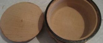
On wood
Compared to a metal workpiece, a wooden workpiece is more amenable to processing, which is why it is possible to carry out processing not only with a lathe cutter, but also with hand chisels and crowns intended for this operation.
When turning, instead of the usual shavings, wood dust remains, so you need to work strictly in a respirator, turning on the hood. It would be a good idea to remove oil spills on the machine in advance and install a vacuum cleaner on the tool holder, which will simplify cleaning after work.
Wooden balls for stairs
More and more people are seeking to move into private homes. That is why they build houses from brick or wood, think through the ideal layout and furnish the house according to their taste. To do this, they hire architects and designers, together with whom they create sketches describing any small details. During the planning process, they even think about what the front door will be like, whether wooden balls will be used for the stairs or left without decoration. This should be the approach to the construction of housing itself, because the comfort of the future home directly depends on it. All the little things, even the balls for the stairs, are very important when creating a harmonious space.
Alternative methods for making a topiary base
Polyurethane foam
We squeeze the polyethylene foam into a plastic bag to get a blank - a figure close to the shape of a sphere, but definitely larger than the required diameter of the ball. We wait until the sealant has completely hardened, remove the bag, and use a utility knife to give the mass the desired shape - not just a ball.
DIY foam ball
Instead of polyurethane foam, you can use a foam blank, for example, packaging from household appliances, or glue several sheets together to obtain the required thickness.
But the foam is non-uniform and crumbles a lot: making a topiary ball of the correct shape is difficult, and a lot of debris remains. You can also cut a base for a flat topiary from a foam sheet.
Papier-mâché technique
We inflate the balloon to the desired size, coat the surface with PVA, glue sheets of paper (you can use toilet paper), fragments of old newspapers or napkins. We continue to increase the mass, generously coating each layer with glue, gaining a thickness of at least 7-10 mm.
After the workpiece has completely dried, carefully deflate and pull out the balloon; the frame remains. The result was a fragile but original ball for topiary using the papier-mâché technique. The method is labor-intensive, the base takes a long time to dry.
Knitting thread
The method exactly imitates the papier-mâché technique, but instead of paper, knitting threads are used: the result is a frame suitable for a light crown. We do not recommend using twine instead of yarn: the material is expensive and strongly absorbs glue.
My mother and I make delicate openwork balls from wicker
There is enough work for everyone in the New Year's workshop. Handicraft mothers can easily cope with the simplest preparation of balls and weave them from willow twigs. Such toys do not even need additional painting; the airy structure of the balls will only emphasize their weightlessness, but if desired, the toys can be gilded or painted in different colors. To hang a wooden Christmas ball, just tie a small thread or a satin ribbon to one of its sides.
The ball will be neater and the vine will bend easier if, before weaving, the willow branches are first boiled for 30 minutes and the bark is removed from them.
Ready-made balls for the tree of happiness
Purchased blanks and improvised bases for topiary:
- Styrofoam ball. For the tree of happiness, it is advisable to use ready-made foam balls with a diameter of 7 to 30 cm.
- Hanging rattan. Ready-made rattan balls are available at decor stores. In addition, you can make them yourself (rattan is wrapped around a balloon).
- Rubber ball. Limited selection of trunks for topiary: only a cable is suitable, which must be attached to the outside of the ball.
- A ball of knitting thread.
- Chipboard is a die-cut made of thick cardboard. Blank for flat topiary on a magnet, thickness 1-3 mm.
- Tennis ball. For miniature trees.
- Ostrich egg. An original base for Easter topiary. Ostrich eggs are very durable and decor sticks well to the surface.
- Foam ball. Multi-colored products are used by magicians to perform tricks, but are also great for our purposes!
- Wooden ball. They are rarely used, but for a certain design a wooden base is optimal.
Figured basics
The sphere is the most popular, but not the only shape for the basic crown of the tree of happiness. Figured blanks, usually made of polystyrene foam, are sold in stores that sell craft supplies. Topiary bases come in many different forms:
- heart;
- egg;
- cornucopia;
- Christmas wreath;
- ring;
- house;
- bike;
- dollar;
- star;
- pumpkin;
- apple;
- horseshoe.
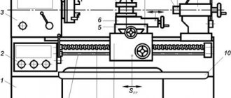
How to turn a cone on a lathe: diagrams, methods
How to turn a cone on a lathe
Lathes are used to turn workpieces during turning by using special cutters. If you have some experience, you can turn not only parts of a regular shape, but also, for example, a conical surface. To create a cone, you must have certain skills on a lathe.
Rotating the upper caliper slide
You can carry out the cone turning process using the following recommendation:
- We take the workpiece and secure it in the spindle, as well as the tailstock. Considering that the cone is manufactured with high precision, the diametrical size and angle may have slight deviations. If the workpiece is made of hard material, carbide cutters should be selected.
- Processing can only be carried out in compliance with safety precautions through the use of personal protective equipment.
- Selecting the cutting speed on the lathe. Machining of conical surfaces can be carried out at a speed that is selected depending on the durability of the cutting edge and the hardness of the material. If there is no exact data that allows you to calculate the cutting speed, you should follow the test path - from lower to higher values.
- The installed workpiece must be given a cylindrical shape. For this, a through cutter is used, first roughing is carried out to remove a large amount of unnecessary metal. Processing near the cams is carried out with a bent cutter.
- The production of precision parts occurs in two passes: roughing and finishing. On a lathe, finishing turning is carried out with a special cutting tool at a certain speed and feed.
- To create small conical surfaces, the top of the caliper is rotated at a certain angle, which should be equal to half the angle of the cone at the apex.
In a similar way, you can create conical surfaces without using a special device.
Method of displacement relative to the axis of centers
Shifting the centers also makes it possible to obtain a Morse taper on a lathe. However, in this case, turning can only be done on external conical surfaces. The advantages of the method under consideration include:
- It is possible to make a long Morse taper.
- A mechanical support feed is used, which makes it possible to use conventional models of lathes.
Center axis offset
Significant disadvantages include:
- Low precision with which the part can be made.
- In the process of obtaining a cone, the center holes become skewed.
The amount of displacement of the tailstock during the creation of conical surfaces is determined using a right triangle.
Cone ruler
Some lathes are equipped with special tapered rulers. Such a device allows you to process external and internal surfaces when the angle of inclination does not exceed 12 degrees. In this case, a cone shape can be made by combining longitudinal and transverse transmission.
When using a ruler, you can select the angle that will be created by simultaneously moving the caliper in the longitudinal and transverse directions. A special ruler allows you to maintain the correct angle throughout.
Using a wide angle cutter
A fairly simple way to obtain a tapered surface on a lathe is to use a corner cutter. With its help, you can create a cone of short length; the cutting edge should be straight. The angle of the taper can be adjusted by sharpening the edge or setting it at a specific angle to the workpiece.
Turning a cone with a cutter
All of the above methods require certain skills in operating a lathe. In some cases, for large-scale production, special copiers are made. For small-scale production, a method that uses a ruler or turning the lathe slide or shifting the headstock is suitable.
Devices for processing spheres
Ball turning
When people talk about spherical surfaces, they usually think of a ball. In reality, we will talk about spheres, which are sections of the general surface of a part. Such parts having spheres (spherical and torus surfaces) include: dies, punches, ball joints, footplates, taps, lenses, tips, fittings, nipples, supports, hubs, ball joints, valves, rollers, rolls, flywheels, press -shapes, worm gears, etc.
Let us divide all spheres into convex and concave and classify them based on their location on the surface of the part. In Fig. 49 shows convex ones, and in Fig. 50 concave spheres. Some spheres, by their location, have a common axis of symmetry with the part (Fig. 49, b - her Fig. 50, a - c), others do not have a common axis of symmetry with the part (Fig. 49, a, g, h and Fig. 50 , d - h).
Rice. 49. Convex spheres
Processing the spheres represents the definition of difficulty. Devices for processing and measuring precision spheres of large and small radii (1 ... 200 mm), having a 6th grade and a surface roughness of 0.32 ... 0.04 microns, have been introduced into production. The technological process of processing spheres is reduced to turning, grinding, polishing and diamond smoothing.
Rice. 50. Concave spheres
In order to understand the variety of devices and better know which devices to use in which case, we classify them according to the nature of the movement of the cutter: devices with translational movement of the cutter (Fig. 51, a, b) and with rotational movement (Fig. 51, c).
Rice. 51. Devices for translational (a, b) and rotational (c) movement of the cutter
Devices with a translational movement of the cutter are less versatile and have more disadvantages compared to devices with a rotary movement. Continuous changes in the plan angles of the cutter during its translational movement along the curved surface of the part and wear of the cutting edges lead to distortion of the geometry of the sphere and an increase in surface roughness. In addition, the size of the sphere surface that can be processed without turning the cutter is limited. For example, with a plan angle of 60°, you can machine the surface of the sphere at no more than an angle of 120° (Fig. 51, a).
To reduce these disadvantages, in devices with translational movement of the cutter, a roller or a spherical tip is used instead of a probe, and a circular cutting edge of a certain radius is sharpened on the cutter (Fig. 51, b). In this case, the radius ratio is maintained according to the formula
R1 + R2 = R3+ R4, where, respectively, the radii are: R1 - roller; R2 - copier; R3 - incisor; R4 - spheres.
Replacing the stylus with a roller or spherical tip introduces additional difficulties associated with the manufacture of cutters. At the same time, the general disadvantage of such devices is not eliminated due to the presence of gaps in the device mechanisms. There remains a distortion of the geometry of the sphere in the zone of the O - O axis (Fig. 51, a, b). These gaps manifest themselves when the direction of movement of the mechanism carrying the cutter changes, and when the direction of pressure on the roller or probe changes when sliding along the copier.
In addition, when processing a sphere with devices with translational movement of the cutter, it is difficult to control its shape. To do this, it would seem that it is enough to grind the sphere first and, by measuring, make sure that its geometric shape is correct. But this technique does not give the desired results, since during preliminary grooving the sphere turns out to be distorted. Measurements without distortion can be made only when the sphere is machined to the required size.
Devices with translational movement of the tool are not suitable for performing diamond smoothing, since the convex working part of the diamond in the form of a sphere or cylinder is limited in size and it can smooth only with a constant orientation relative to the surface being processed.
Devices with rotational movement of the cutter (Fig. 51, c) do not have these disadvantages. The cutting angles remain unchanged. Wear of the cutter does not cause distortion of the shape of the sphere and can only affect the change in the size of the sphere, which is easily eliminated by adjusting the machine. Such devices are convenient for the use of diamond burnishing and are becoming increasingly used.
Turner services
Finding someone who will provide turner services in Moscow is not very easy. There are fewer and fewer good turning specialists left, as young people do not go to study for blue-collar jobs. Turning works photo. We are proud that we have excellent turners in our team. Before answering your question about the cost of turning services, we need to know from you:
- drawing or drawing with exact dimensions (or sample part) (can be sent by email
- type of material processed and type of work required
- required quantity
- material for work, yours or ours
- other recommendations and wishes.
We try to fulfill all orders on time and with high quality. Our prices are quite affordable. Turning works in Moscow.
metal turning works master turning works price
TURNING SERVICES. Turning work photo
Despite the presence of many methods of forming processes (casting, powder metallurgy, etc.), cold metal working is widespread in the engineering industry.
Very often it is simply unprofitable to produce special casting molds and purchase equipment. Or the only way to make a part is from a piece of metal (plate, rod, profile).
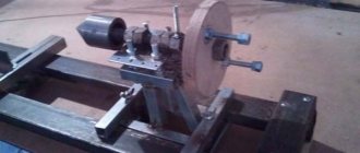
Turning with fixture
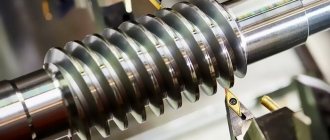
A more complex way is to turn a ball on a machine using a pre-fabricated fixture. Due to the ideality of the spherical surface, the manufacturing accuracy of the mechanism must be maximum. In the following proposed video, the device is manual, and the processing is partially performed after preliminary turning with cutters to a shape close to a ball:
A special feature of this method of turning spheres is that it can only be used when processing soft metals. But this task is quite common, and with a large number of orders, such a device can always help the turner.
Frame wrapping for decorative wood
The base of the crown of 8 out of 10 topiaries - the backing - performs 2 functions: it improves the gluing of materials, and is also a base decorative layer that masks the color of the ball.
Pre-winding or painting the base prevents the material from burning when gluing the decor with a hot glue gun.
Substrate manufacturing methods:
- Sisal wrapping.
- Twine.
- Wrapping with knitting or sewing threads.
- Gauze or fabric covering.
- Painting a topiary ball (required when gluing coffee beans).
- Apricot kernel base.
1. Wrapping with sisal 2. Wrapping with twine or yarn 3. Wrapping with thread 4. Covering with gauze 5. Painting the base 6. Backing with apricot kernels
Of course, a ready-made foam ball is the best choice for a base for a tree of happiness, with virtually no disadvantages. However, you should not neglect free methods: we recommend using a topiary ball made from newspapers - the best option, also without flaws and, moreover, with minimal costs!
Step-by-step instruction
This manufacturing method is suitable for both metal and wood. Additional machine equipment and non-standard designs are not required. All you need is a sample. As such, you can use a machine-turned ball with a rod or a ball from a bearing of the required diameter.
To be able to install the latter, you need to rigidly attach a shank rod of the required diameter exactly in the center to it. This can be done by welding or threaded connection.
Workpiece selection
In both cases, the workpiece must have a cylindrical shape with a margin (approximately 1/10) of length for fastening in the chuck and a small allowance for processing along the width. If steel rod is a standardized material in metallurgy, then for carpentry work most often the raw material is supplied in the form of timber. Before starting work, you need to give the material the shape of a cylinder, secure it in a driving chuck and grind it.
Important!
Before starting work, visually check the workpiece for curvature by rotating it in the jaw chuck.
Create a groove
The diameter of the ball is equal to the diameter of the grooves and the distance between them. Clamping the workpiece in a three-jaw chuck, machine the future part at a given distance from the end. The created groove will serve as a kind of mark when processing using cross feed. It is also necessary to countersink the hole for subsequent fixation in a rigid center when processing the workpiece with abrasive.
Carry out fixation
Now, using a rigid center installed in the tailstock and a chuck, we fix it. Having loosened the chuck with a key, we place the workpiece in it. Now you need to make an indent from the groove and securely secure the part in the chuck. The template must be secured in the tailstock. Having verified the required distance and position of the workpiece relative to the sample, you can proceed to the next step.
Turn using front feed
To give the workpiece a ball shape, it is necessary to use two identical cutting tools, usually with a rounded cutting edge. Attach the cutters to the caliper holder on one side with the same offset.
The essence of the method is to guide the copy cutter touching the circumference of the spherical sample, while the mirror-mounted cutter grinds the workpiece, repeating the vector of movement of the second one.
Turning is carried out by direct and transverse feed, as a result of which a surface in the form of a ladder is formed. After shaping the material into a ball, a finishing pass is made with a small thickness of the layer being removed and feed. Removal of layers of material is carried out within the groove. After which it must be removed, combining the transverse and front feed.
Make a shape using a file
After processing with a cutter, a stepped surface is formed, which must be processed with a file. For metal, you should choose a file with a cut number 0 or 1. For wood, with a simple single cut. A tool with a semicircular working part will greatly simplify the process, but is not a prerequisite. It is advisable to use a support without a cutter as a stop; it will serve as a reliable support and reduce the likelihood of injury.
We install the caliper platform at the level of the part before the operation. Having removed the sample, we bring the rigid center to the hole previously created with a countersink, moving the headstock forward and fixing it. We start the machine at minimum speed, waiting for the spindle to pick up speed. We rest the shank or handle of the file against the support and, with a smooth movement from top to bottom, lower the working part of the file to the workpiece.
In this case, you need to hold it firmly with both hands on both ends of the tool to prevent the tool from hitting. If you are using a flat file, you must move it smoothly from edge to edge for uniform processing.
Important!
Move the file opposite to the movement of the spindle to prevent the tool from kicking back.
Clean with sandpaper
When finishing, use sandpaper. Each material will require a different grit of abrasive. For metal in the region of P800-P1000, for wood P400-P600. There are two ways to polish a surface using an abrasive belt. In the first case, the canvas is stretched with both hands and pulled onto the surface to be treated; in the second, the sandpaper is attached to a special block.
The raw ends used for fastening are removed by hand. As you can see, manufacturing a part in the form of a ball is a completely easy and feasible task, without requiring highly complex add-ons on current equipment.
Copier turning
To obtain the simplest copying device, you will not need much at all - a spherical template of a suitable diameter and two identical cutters installed in a cutter holder on one side with the same offset. Particular attention should be paid to the correct setting of the copying device - set the cutting tool at the same distance.
It is very convenient to do this using any part that has a cylindrical shape - a sample of a pipe or a steel rod. To set up, it is enough to secure one of the cutters with bolts, and install the second without fastening. Smoothly move the tool holder with the cross-feed handle, wait until both cutting edges touch the mandrel and fix the loose tool.
As a mandrel, you can use a ball on a rod pre-machined on a CNC machine or a ball from a bearing of a suitable diameter. To make it easier to secure the latter, it is necessary to weld a round rod of suitable diameter strictly in the center.
Turning technology is not particularly difficult. Initially, using a working cutter, usually a cutting cutter with a rounded cutting edge, rough grinding is performed. In this case, the copier (second cutter) moves touching the spherical template fixed in the tailstock quill through an adapter.
After preliminary giving the workpiece a shape close to the desired one, finishing turning is performed with a small thickness of the cut layer and feed. Final processing, if necessary, can be done with fine-grain sandpaper. The technology is demonstrated in more detail in the video below:
Is it possible to do this?
Creating a spherical part on turning equipment is a simpler process than it seems at first glance. In this case, you can use both auxiliary equipment, if the production of a small batch is planned, and standard equipment of the machine in the case of piece production. The most affordable way is turning using a previously prepared template.
For metal
Working with metal is an order of magnitude more difficult compared to other materials due to its higher hardness, but it is more familiar and does not have unusual features. Turning a ball will take at least two passes and will require working at high speeds to obtain a satisfactory result. In general, the process is little different from other turning operations and has no specific specifics.
On wood
Compared to a metal workpiece, a wooden workpiece is more amenable to processing, which is why it is possible to carry out processing not only with a lathe cutter, but also with hand chisels and crowns intended for this operation.
When turning, instead of the usual shavings, wood dust remains, so you need to work strictly in a respirator, turning on the hood. It would be a good idea to remove oil spills on the machine in advance and install a vacuum cleaner on the tool holder, which will simplify cleaning after work.
How to turn a cone on a lathe
Lathes are used to turn workpieces during turning by using special cutters. If you have some experience, you can turn not only parts of a regular shape, but also, for example, a conical surface. To create a cone, you must have certain skills on a lathe.
Taper turning
Rotating the upper caliper slide
You can carry out the cone turning process using the following recommendation:
- We take the workpiece and secure it in the spindle, as well as the tailstock. Considering that the cone is manufactured with high precision, the diametrical size and angle may have slight deviations. If the workpiece is made of hard material, carbide cutters should be selected.
- Processing can only be carried out in compliance with safety precautions through the use of personal protective equipment.
- Selecting the cutting speed on the lathe. Machining of conical surfaces can be carried out at a speed that is selected depending on the durability of the cutting edge and the hardness of the material. If there is no exact data that allows you to calculate the cutting speed, you should follow the test path - from lower to higher values.
- The installed workpiece must be given a cylindrical shape. For this, a through cutter is used, first roughing is carried out to remove a large amount of unnecessary metal. Processing near the cams is carried out with a bent cutter.
- The production of precision parts occurs in two passes: roughing and finishing. On a lathe, finishing turning is carried out with a special cutting tool at a certain speed and feed.
- To create small conical surfaces, the top of the caliper is rotated at a certain angle, which should be equal to half the angle of the cone at the apex.
In a similar way, you can create conical surfaces without using a special device.
Method of displacement relative to the axis of centers
Shifting the centers also makes it possible to obtain a Morse taper on a lathe. However, in this case, turning can only be done on external conical surfaces. The advantages of the method under consideration include:
- It is possible to make a long Morse taper.
- A mechanical support feed is used, which makes it possible to use conventional models of lathes.
Center axis offset
Significant disadvantages include:
- Low precision with which the part can be made.
- In the process of obtaining a cone, the center holes become skewed.
The amount of displacement of the tailstock during the creation of conical surfaces is determined using a right triangle.
Cone ruler
Some lathes are equipped with special tapered rulers. Such a device allows you to process external and internal surfaces when the angle of inclination does not exceed 12 degrees. In this case, a cone shape can be made by combining longitudinal and transverse transmission.
https://youtube.com/watch?v=HysW_hx6pZ0
When using a ruler, you can select the angle that will be created by simultaneously moving the caliper in the longitudinal and transverse directions. A special ruler allows you to maintain the correct angle throughout.
Using a wide angle cutter
A fairly simple way to obtain a tapered surface on a lathe is to use a corner cutter. With its help, you can create a cone of short length; the cutting edge should be straight. The angle of the taper can be adjusted by sharpening the edge or setting it at a specific angle to the workpiece.
Turning a cone with a cutter
All of the above methods require certain skills in operating a lathe. In some cases, for large-scale production, special copiers are made. For small-scale production, a method that uses a ruler or turning the lathe slide or shifting the headstock is suitable.
If you find an error, please select a piece of text and press Ctrl+Enter.
Principles of turning
The technology of metal turning involves the use of special machines and cutting tools (cutters, drills, reamers, etc.), through which a layer of metal of the required size is removed from the part. Turning is performed through a combination of two movements: the main one (rotation of the workpiece fixed in a chuck or faceplate) and the feed movement performed by the tool when processing parts to the specified parameters of their size, shape and surface quality.
Due to the fact that there are many techniques for combining these movements, turning equipment is used to work with parts of various configurations, and also carry out a whole list of other technological operations, which include:
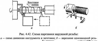
- cutting threads of various types;
- drilling holes, boring them, reaming them, countersinking;
- cutting off part of the workpiece;
- turning grooves of various configurations on the surface of the product.
Main types of metal turning work
Thanks to such a wide functionality of turning equipment, a lot can be done with it. For example, it is used to process products such as:
- nuts;
- shafts of various configurations;
- bushings;
- pulleys;
- rings;
- couplings;
- gear wheels.
Naturally, turning involves obtaining a finished product that meets certain quality standards. In this case, quality means compliance with the requirements for the geometric dimensions and shape of parts, as well as the degree of surface roughness and the accuracy of their relative position.
To ensure control over the quality of processing on lathes, measuring instruments are used: at enterprises that produce their products in large series - maximum calibers; for conditions of single and small-scale production - calipers, micrometers, internal gauges and other measuring devices.
Measuring tools often used in turning
The first thing that is considered when learning turning is the technology of metal processing and the principle by which it is carried out. This principle lies in the fact that the tool, cutting its cutting edge into the surface of the product, clamps it. To remove a layer of metal corresponding to the size of such an incision, the tool must overcome the adhesion forces in the metal of the workpiece. As a result of this interaction, the removed layer of metal is formed into chips. The following types of metal shavings are distinguished.
Merged
Such chips are formed when workpieces made of mild steel, copper, tin, lead and their alloys, and polymer materials are processed at high speeds.
Elemental
The formation of such chips occurs when workpieces made of low-viscosity and hard materials are processed at low speed.
Broken shavings
Chips of this type are obtained when processing workpieces made of material characterized by low ductility.
Stepped
The formation of such chips is typical for medium-speed processing of workpieces made of medium-hard steel and parts made of aluminum alloys.
Types of chips during turning
Using a special design
The process can be significantly simplified by using a special design. The device with which the work in question can be carried out allows you to rotate the cutter along a given circle. In this case, the following nuances can be noted:
- The structure must be rigidly fixed, for which you will have to make holes in the frame for its fastening.
- The metal is also pre-processed in a standard way using longitudinal-transverse feed.
- The design features of the design limit the minimum and maximum diameter of the resulting ball.
- In this case, you will also have to use emery to remove metal at the attachment point.
- The entire surface, except for the attachment point, is processed at one time. Pre-treatment for metal removal is necessary because in this case the cross feed is not adjustable (the diameter of the part is adjusted by the distance at which the cutting edge is located from the attachment point).
- The correct shape is achieved without the need for special processing skills.
- You can get a batch of spherical parts that will have the same dimensions.
In conclusion, we note that such a device is often created by hand. Lathes of older models are not suitable for automating the production process of producing spherical bodies.
If you find an error, please select a piece of text and press Ctrl+Enter.
Designation of taper in the drawing
When creating technical documentation, all established standards must be taken into account, otherwise it cannot be used in the future
When considering the taper designation in the drawings, attention should be paid to the following points:
- The diameter of the large base is displayed. The figure under consideration is formed by a body of rotation, which is characterized by a diametrical indicator. In the case of a cone, there may be several of them, and the change in the indicator occurs smoothly, not stepwise. As a rule, such a figure has a larger diameter, as well as an intermediate one if there is a step.
- The diameter of the smaller base is applied. The smaller base is responsible for forming the required angle.
- The length of the cone is calculated. The distance between the smaller and larger bases is an indicator of length.
- Based on the constructed image, the angle is determined. As a rule, appropriate calculations are carried out for this. In the case of determining the size from a printed image, using a special measuring device, the accuracy is significantly reduced. The second method is used when creating a drawing for the production of non-critical parts.
The simplest designation of taper also provides for displaying additional dimensions, for example, reference. In some cases, a taper sign is used, which makes it immediately clear about the difference in diameters.
There are quite a large number of different standards that relate to the designation of taper. The features include the following:
- The angle can be specified in degrees as a fraction or as a percentage. The choice is made depending on the area of application of the drawing. An example is that in the mechanical engineering field the value of a degree is indicated.
- In the mechanical engineering field, the concept of normal taper is included in a special group. It varies within a certain range and can be 30, 45, 60, 75, 90, 120°. Similar indicators are characteristic of most products that are used in the assembly of various mechanisms. At the same time, it is much easier to maintain such values when using turning equipment. However, if necessary, inaccurate angles can be maintained, it all depends on the specific case.
- When drawing the main dimensions, a drawing font is used. It is characterized by quite a large number of features that must be taken into account. Tabular information is used for correct display.
- To begin with, the taper icon is indicated from which the arrow is drawn and the value is displayed. The display features largely depend on what kind of drawing. In some cases, a large number of different sizes are applied, making taper application much more difficult. That is why it is possible to use several different methods for displaying such information.
In the drawing, the indicator in question is indicated in the form of a triangle. This requires a digital value that can be calculated using various formulas.
Read also: Not an integral part of a metal plane
DIY lathe headstock
The headstock for a lathe can be made independently without any problems.
For this purpose you will need:
- Wooden plank.
- Plywood, ten millimeters thick.
- A thin sheet of metal that is cut with special scissors.
It is much easier to make a headstock with your own hands if the basis of this device is an ordinary unnecessary drill. After this, it will only be necessary to make a stand, which will subsequently be the mounting platform for the drill, which has a strict horizontal axis.
The middle of the front and middle of the tailstock must be securely fastened, this is extremely necessary. For the tailstock, it is necessary to establish in advance the limits of the possibilities of wrapping along the axis and rigidly securing it in place.
The power of the electric motor should be selected independently, based on the purpose of the turning device. Although the engine power does not need to be less than 250 W. Otherwise, it will not be possible to turn out any necessary parts.
Do-it-yourself ball for a lathe
Here is one of the links to the balloon that I liked. » >
Damn, this is even more interesting than proxon, here you just need to make equipment for replaceable plates
Aspirant wrote: Damn, this is even more interesting than proxon,
Much more interesting. That's where else to find time to make it.
I have a designer part-time. While he is busy, how he will free himself (by the end of September from the gardens) is a mystery. then at the factory or I’ll create it myself
Aspirant wrote: I have a designer part-time
It’s good for you, but I’m my own Petlyura. And a designer, and a draftsman, and a mechanic, and a turner, etc.
Yes, I’m just like that, I just realized that I can’t do everything myself, so I’m turning to pensioners because they are an order of magnitude more experienced, wiser and smarter than us young people in everything. only we are nimble and that’s what makes us different
I can’t say this about myself.
Aspirant wrote: On Wednesday I received a little ball I’m thinking of adapting it to a Corvette or making an analogue for a large machine, I’m bragging
If possible, give the dimensions of this device. Here's a video about the spherotochka Here's more
At the request of the workers, I am developing the topic and posting drawings of the balloon I bought. Request to comrades who are at the chipmaker - make links to this topic, I want to encourage people to benefit the cause
and this is a photo of the glands themselves
And here is the assembled ball in position for turning external spheres
And now the main thing is that without a rectangular support, the cutting point coincides with the axis of rotation of the workpiece on the Corvette 400 when installing the equipment instead of a tool holder
We make a wood milling machine for a home workshop
Milling machines are necessary for working with shaped wood parts. They are used for flat milling and profile processing. Professional equipment is multifunctional and costs a lot of money, so more and more “homemade” people are assembling such equipment for workshops and garages on their own.
Small DIY milling machine
The set of homemade wood milling machines includes:
- Drive mechanism. This is an engine whose power ranges from 1-2 kW. With such a motor, you can use various tools to work with wood without fear of failure.
- Lift for adjustment. Typically, it includes a body, sliding skids, carriages, a fixing screw and a threaded axle. During operation, the carriage moves up and down, and a screw is needed to fix it at the required level.
- Support. The table is made from solid wood.
Before assembly, be sure to draw up a detailed drawing with all dimensions. For manual wood milling machines, you need to think through everything in advance down to the smallest detail.
3D model of a table for a manual machine Equipment components Dimensions of the working element Cutting on a milling machine
The sequence of self-assembly of a convenient and practical wood milling machine for a home workshop is described in the video instructions:
If you are thinking about buying your own equipment rather than assembling it yourself, then to understand how much a manual wood router costs, look at the table with models and prices:
| Model name | Specifications | |
| Milling table Kraton MT-20-01 | site size | 64 by 36 cm |
| possibility of vertical work | There is | |
| equipment weight | 15.7 kg | |
| Milling table Kraton MT-20-01 | ||
| Milling machine Corvette-83 90830 | engine power | 750 W |
| transmission type | belt | |
| spindle speed | 11,000 rpm | |
| vertical stroke | 2.2 cm | |
| spindle diameter | 12.7mm | |
| Milling machine Corvette-83 90830 |
Making a CNC milling machine with your own hands
You can make your own numerical control equipment with your own hands. To do this, select suitable drawings of a CNC wood milling machine. You will need to assemble the model with your own hands strictly according to them.
Ready-made machine for a home workshop Equipment components Detailed assembly diagram Model of multifunctional equipment
Wood milling machines must have great strength, so it is better to take a rectangular beam mounted on guides as a basis. The lifespan of home equipment and its performance depend on proper assembly. Watch the video instructions for making such a device:
Below are photos of finished models of CNC woodworking machines with your own hands from professional “homemade” ones: