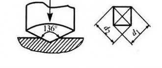
Average diameter of threaded connection
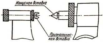
To determine the average diameter of a thread, you need a micrometer with special tips in the form of a cone and a cutout. It is used to determine the size of the part at the top of the thread and at the root to calculate the average value. When selecting a kit, it is necessary to take into account the measurement limit, which is indicated in the marking with the letter M and numbers indicating the minimum and maximum allowable thread pitch. Also, to obtain the average thread value, calipers with ball tips are used, the profile of which matches the type and pitch of the thread. The tips are calibrated on several sides of the part for the most accurate result.
Thread calibration after galvanizing!
#1 Glavtech
- Name: Viktor
- Field of activity: Manufacturing
Registered 2 messages
Tell me how to calibrate threads after galvanizing; it is advisable to avoid manual calibration of parts using dies. Thanks in advance
- Name: Bityukov A.V.
Field of activity: Manufacturing 710 messages registered
Doesn’t the fact that calibration damage the coating bother you?
- Name: Viktor
Field of activity: Manufacturing 2 messages registered
No! Because Now we do the calibration manually, with a die!
#4 Waltham
- Name: Vanya
Field of activity: Technology development 19 messages registered
Doesn’t the fact that calibration damage the coating bother you?
I'm also interested in this moment. galvanizing to a sufficient depth is carried out so that calibration does not overlap it?!
#5 ingenercons
- Name: Vladimir
Field of activity: Construction 4,549 messages registered
More than once I have seen in the technical requirements the entry after coating, calibration of the thread is prohibited. Actually I agree with this phrase. The meaning of coverage is lost.
Field of activity: Technology development 2,771 messages registered
#7 ingenercons
- Name: Vladimir
Field of activity: Construction 4,549 messages registered
A question arose close to the topic, let’s say there is a bolt with a zinc coating and a similar nut, they tightened it once to check, a second time to check by the customer, and then the installation stage began and the coating peeled off. Or is this not a real situation))
#8 statist
- Field of activity: Design
395 messages registered
A question arose close to the topic, let’s say there is a bolt with a zinc coating and a similar nut, they tightened it once to check, a second time to check by the customer, and then the installation stage began and the coating peeled off. Or is this not a real situation))
If there is too much phosphorus in the steel, for example, then the zinc may flake off. And in principle, such a situation may arise: the engineering staff carefully tightened it a couple of times - everything is fine. And the locksmith Vasily kissed the key with all his heart, and goodbye galvanization. Then we take some polyurethane zinc paint, a brush and bring everything back to its divine glory.
#9 ingenercons
- Name: Vladimir
Field of activity: Construction 4,549 messages registered
How well will the paint protect? I heard there are special formulations. but haven't used it in practice. Or here’s a situation closer to practice: they threw in too long bolts in a hurry, then it doesn’t work during installation, they sawed off with a grinder and inserted it, but in fact the end is exposed metal.
#10 statist
- Field of activity: Design
395 messages registered
Well, of course, it will not replace hot-dip galvanizing itself. But for careful installation and subsequent “not touching” it is quite suitable.
Field of activity: Technology development 2,771 messages registered
#12 ingenerkons
- Name: Vladimir
Field of activity: Construction 4,549 messages registered
Not varnish is not always suitable, just take the same weather conditions, it is better to immediately paint over it with enamel along with the flanges. But what if the conditions involve exposure to various aggressive environments?
Field of activity: Technology development 2,771 messages registered
#14 Disegnatore
- Field of activity: Design
283 messages registered
“Calibration of threads after galvanic coating is not performed/allowed.” A similar phrase can be found in a bunch of books on the topic (for example, Melnikov P.S. Handbook on electroplating in mechanical engineering) and GOSTs (GOST R 51906-2002).
If you don’t care about galvanizing in the thread zone, then the manufacturer can relieve itself of responsibility by including in the contract phrases like “Threaded connections after galvanizing are subject to calibration by the Customer.” or “In the thread area, the thickness of the coating is not regulated.” And then at least calibrate, at least “run” the thread again, removing the galvanic coating to the “ferrous” metal.
source
Caliber
Unlike a micrometer, calipers and other instruments, for each diameter, type and thread pitch there is its own separate gauge, which is the standard of the maximum permissible value. To match the thread to the gauge, it is necessary that the latter can be screwed freely without any effort or gaps along the entire length. There are nut gauges and plug gauges for external and internal threads, respectively. The advantage of this method is the simplicity and accuracy of measurement. The main disadvantage is the need to use a set of gauges when checking more than one type and diameter of threaded connections.
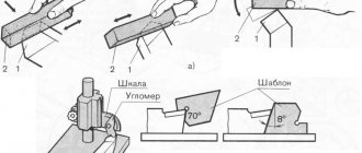
Defect detection methods
The technical condition of parts is determined by external inspection, tapping, dimensional measurement, checking using universal tools, special templates, devices, fixtures and stands.
During inspection, external damage to parts, deformations, cracks, scuffs, breaks, burnouts, cavities, corrosion, leaks, etc. are revealed.
By tapping, the condition of fixed joints is determined (loose fits of rivets, pins, pins, rings), and the presence of cracks in body parts. When lightly tapped, tightly seated and stationary parts produce a ringing metallic sound, and if there are cracks or a weak fit, they produce a rattling, dull sound.
Using universal measuring instruments, the actual dimensions, deviations from the dimensions, shape, and relative positions of the structural elements of the part are determined. The gap in the connections is measured. To determine the geometric parameters of parts, calipers, micrometers, indicator bore gauges, caliper gauges, etc. are used. The measurement procedure, the tool used, devices, and the location of measurements are indicated in the corresponding technological maps.
In order to increase productivity and simplify the control and sorting of parts, defect detection gauges (hard limit tools) and templates are used in specialized repair production. Templates are made according to the principle of single-limit staples.
Curvature, twisting, beating and warping of the surfaces of parts are determined using special devices and devices. For this purpose, surface plates are used; universal tripods with dial indicators, special prisms and centers, rulers, squares, probes.
Hidden defects in parts (cracks, cavities, etc.) are detected using pneumatic, hydraulic, magnetic, capillary and ultrasonic methods.
The pneumatic method is used to check the tightness of radiators, fuel tanks, fuel lines, rubber bladders, etc. The part is immersed in a bath of water. If it has more than one hole, then the others are closed with plugs, and air is supplied to the remaining ones. The location of the defect is determined by the bubbles of escaping air.
Using the hydraulic method, special stands are used to check the tightness of block jackets, cylinder heads, engine suction pipes, etc. The part is installed on a stand, the holes are closed with special plugs with gaskets, the internal cavity is filled with water and a certain pressure is created. Water leakage will indicate the location of the crack. The hydraulic method is also used when checking plunger pairs, discharge valves of high-pressure fuel pumps, injectors and fuel lines after repair.
Magnetic flaw detection is used to detect hidden cracks, pores, and slag inclusions in parts made of ferromagnetic materials. The method is based on the appearance of a magnetic scattering field in the area where the defect is located when magnetic force lines pass through the part. Magnetization is accomplished by passing an electric current through the part. Before magnetization, the part is sprinkled with ferromagnetic powder or poured with a suspension consisting of transformer oil (40%), kerosene (60%) with the addition of 50 g/l of magnetic powder. Powder particles are concentrated at the edges of the defect, like the poles of a magnet, and indicate its location and configuration.
Capillary methods make it possible to detect discontinuities (cracks, pores, etc.) in parts made of ferromagnetic and non-magnetic materials. They are based on the ability of some liquids to penetrate the smallest surface discontinuities. These methods include fluorescent and color flaw detection.
The simplest of capillary methods is color flaw detection. The penetrating liquid (kerosene - 65%, transformer oil - 30%, turpentine - 5%) is painted red (sudan is added, 10 g/l). It is applied to a degreased surface and after 5-10 minutes the part is wiped. To reveal a crack, an oil solution is used, which is applied to the surface being tested. As it dries, a pattern appears on the white surface showing the location of the defect.
Principles of construction of control devices
With automated control of parameters, the objectivity and repeatability of control results are of particular importance. It is obvious that the “human factor” significantly reduces the reliability of the results, therefore, with varying degrees of automation of the measurement process, the collection and processing of information must remain with the machine
In addition, it is important to leave the possibility of integrating a control device into automated production by ensuring that the product is supplied to the control position by workshop automated transport
It is fundamentally important from the point of view of the possible use of devices for monitoring the geometric parameters of threads of couplings and pipes in the same production (uniform operational characteristics, selection of pipe-coupling pairs, unity of rejection criteria) that they are built on the same kinematic diagram, allowing the use of common methods of collection, processing and analysis information about thread parameters. When designing thread inspection devices, the following points can be identified that affect the quality of information and the reliability of the result:
When designing thread inspection devices, the following points can be identified that affect the quality of information and the reliability of the result:
- the size of the controlled zone (surface) of the thread;
- technology for collecting and processing information;
- accuracy of measuring heads positioning in relation to the thread surface in the process of automated feeding and fixing of the object at the measuring position;
- the amount of information received that allows us to formulate adequate rejection criteria.
The UKRT1 and UKRM1 devices developed at TELECON for monitoring the threads of tubing and couplings, respectively, use the method of visual non-contact monitoring of parameters using industrial video cameras operating in transmission for tubing and in reflection for couplings.
To improve inspection performance, two video cameras are used, located in the center plane of the object, providing simultaneous inspection of two thread zones spaced 180º apart. Control of the maximum size of the thread surface is ensured by two scanning mechanisms: rotation of measuring video cameras around the axis of the part in increments of 22.5º (taking into account 2 video cameras of such control zones, 16) and movement of measuring video cameras along the axis of the part along the entire length of the thread. As a result, inspection is carried out on ~75% of the thread surface of the pipe or coupling, which provides sufficient information to make a decision about its suitability.
Of great importance for minimizing systematic measurement errors on automated control devices is the accuracy and repeatability of the relative position of the measuring video cameras and the object. This is especially true in the case of automated supply of parts to the measuring position by workshop vehicles. If the device is intended for measuring several standard sizes of parts, then it is advisable to minimize the readjustment process so as not to lose the reference bases and spatial position of the axes. This can be done either by increasing the field of view (while maintaining resolution) or by using interchangeable measuring heads, pre-adjusted at the factory.
The total position error of the part consists of the error in the shape of the part, the misalignment of the part and the measuring heads, as well as the non-parallelism of the axis of movement of the heads and the base plate. Obviously, to implement the requirements of GOST 633-80, the total error should not exceed 5-10 microns. In this case, the adjustment of the device (including when readjusting to another standard size) should ensure its own error of no higher than 2-5 microns. All this increases the requirements both for the kinematic structure of the device and for the accuracy of manufacturing and assembly of the used units: guides, supports, base plates, etc.
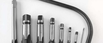
Measuring with a thread gauge
The best option for correctly measuring threads is to use a thread gauge. This is a special tool for measuring cutting pitch. The thread gauge is a body to which probes are attached in the form of thin plates with a comb. The shape of the comb exactly matches the standard thread with a certain pitch.
The following types of thread gauges are distinguished:
- Metric. Allows you to measure the thread pitch of a bolt, nut or other part with a metric thread with a diameter from 1 to 600 mm. The tool has up to 20 measuring plates and allows you to determine thread pitch from 0.4 mm to 7 mm. Indicated by the marking “M60” on the body.
- Inch. Used to measure inch threads, which are usually cut on pipes and pipeline parts, and are also sometimes used on fasteners. The pitch of an inch thread is determined by the number of threads per inch of length of the threaded part of the part. The thread gauge is equipped with 17 measuring plates with a number of turns from 4 to 28. The “D55” marking is used to mark the tool.
- Universal. Equipped with measuring plates for metric and inch cutting. Such thread gauges are widely used in workshops where it is necessary to simultaneously work with parts with both metric and inch threads.
Before determining the pitch, you need to measure the diameter of the thread with a caliper. This is necessary because the pitch range may depend on the diameter.
The process of measuring pitch using a thread gauge is extremely simple. Visually suitable thread gauge plates are applied to the thread being measured. Using the selection method, a plate is selected whose comb will exactly match the thread being measured. Its pitch will correspond to the standard value indicated on the marking of the measuring plate.
The easiest way to measure external threads is this way. If you need to determine the pitch of the internal thread, then the measurement location must be illuminated in order to accurately determine the tight fit of the thread gauge plate comb.
When measuring the pitch of a metric thread, the desired parameter is obtained in millimeters. If it is necessary to measure the pitch of an inch thread, then its value is obtained in the number of turns per inch.
Strengths and weaknesses of the eddy current testing method
- does not involve contact with the surface. There are no traces left. Converters wear out very slowly;
- does not require supply and removal of contact fluid;
- effectively detect cracks emerging on the surface with a depth of 0.1 mm, a length of 2 mm and an opening width of 0.01 mm or more;
- excellent for automated incoming and outgoing inspection of products and materials;
- can be carried out even in the presence of paintwork. Eddy current testing, as a rule, is not hampered by the presence of a non-magnetic coating up to 2 mm thick;
- Suitable for both base metal and all kinds of connections - bolted, riveted and welded. In the latter case, however, you must first remove the reinforcement roller;
- does not require flaw detection consumables;
- harmless to the health of the operator;
- Can be used for moving objects. VK is actively used in the conditions of continuous pipe rolling and foundry production, for checking cylindrical surfaces as holes are formed, etc.
- not suitable for objects with inhomogeneous magnetic and electrical properties. The presence of burns, hardening and local magnetization leads to local changes, which, in turn, provoke the occurrence of false indications;
- is not able to detect defects filled with electrically conductive particles, as well as discontinuities whose opening plane is parallel to the surface under study (or forms an angle with it of less than 10 degrees);
- may not show existing discontinuities on objects with conductive coatings. The same applies to products affected by corrosion. VK is good at recognizing defects that appear on the surface. If this is not observed, then technology is powerless;
- has a relatively shallow depth of the studied zone, usually up to 2 mm. This, of course, is not an X-ray or an ultrasound scan.