Before, during and after installation of fiber laser machines, we always have many questions about gas consumption when cutting metals. Below we provide some background information and tips for correct gas supply and use of auxiliary gases.
Laser grade nitrogen and oxygen used in metal cutting must first be available to the machine at the correct pressure.
For oxygen there must be at least 8 bar (800 kPa), adjustable from 5 to 10 bar.
for nitrogen, up to 20 bar (2 mPa) should be available, adjustable from 10 to 20 bar.
How much gas a car ultimately consumes depends on many factors, such as:
nozzle diameters used for cutting
The larger the hole in the cutting nozzle, the more liters of gas are required per unit of time to maintain the same PRESSURE. If the nozzle diameter is doubled, the gas consumption will be squared higher and will therefore consume 4 times more gas.
cutting gas pressure
Higher pressure often results in a cleaner cutting groove, but it also consumes more gas.
How much oxygen is consumed during welding?
Oxygen allows you to bring the flame temperature to the desired temperature during welding.
Gas-flame processing allows you to obtain high efficiency of work and a good final result. During the work, gaseous oxygen is used. Oxygen allows you to bring the flame temperature to the desired temperature during welding. Gas-flame processing allows you to obtain high efficiency of work and a good final result. During the work, gaseous oxygen is used.
The level of gas consumption will depend on a number of parameters, including the thickness of the wire and metal, as well as the type of seam. Below we provide a table of gas consumption when using the most common mixture with acetylene.
Metal thickness, mm
To find out more details, contact. Our specialists will answer questions about the consumption of a particular gas, as well as the features of its use in various conditions. We will supply you with the type of cylinder you need at the best prices.
source
Gas welding
Gas welding is a type of fusion welding. The source of heat is the high-temperature flame of burned gases in the burner. When performing work, mixtures of oxygen and acetylene, propane and butane, hydrogen, or natural gas are most often used as flammable gases. The metal edges are joined using filler wire, or by melting flanged edges (for metal thickness no more than 2 mm).
Gas welding allows you to connect parts made of almost all metals, and materials such as cast iron, brass, copper, lead are welded in this way better than with electric arc welding. Another advantage of this method is the absence of the need for an electric current source and the simplicity of the welding process.
The prevailing area of application of gas welding is the connection of low-carbon and medium-carbon steels up to 4 mm thick, pipes with a diameter of up to 100 mm and a wall thickness of 3.5 mm, cast iron parts, parts made of non-ferrous metals of various thicknesses, surfacing on steel and cast iron parts. Welding steel of greater thickness using the electric arc method is more productive.
The workplace for gas welding includes oxygen cylinders with reducers (to reduce the pressure of bottled gas), an acetylene generator for oxygen-acetylene welding, safety valves, rubber hoses for supplying gases, torches, welding materials: filler wire and fluxes; plumbing supplies and tools (personal protective equipment, keys, chisels, hammers, metal brushes, etc.), assembly equipment, welder’s table.
Oxygen can be delivered to the welder's station in gaseous form in pressurized cylinders, or in liquid form, then it is converted into a gaseous state using pumps with evaporators or gasifiers. When gas welding, you can change the type of flame by varying the composition of the mixture of combustible gases (Figure 1). A normal flame is characterized by the following relations:
1) oxygen: acetylene = 1.1. 1.2; 2) oxygen: natural gas = 1.5. 1.6; 3) oxygen:propane=3.5.
Oxidizing flame is used when welding brass parts. The carburizing flame involves excess acetylene and is used in welding cast iron. Both types of flame are also used for soldering using carbide solders.
At the beginning of work, the angle of inclination of the mouthpiece is set larger, and then it is reduced in accordance with the values in Figure 2.
At the end of the weld, the angle is reduced so that the metal does not burn out. When welding a seam, perform transverse vibrations with the mouthpiece (Fig. 3) to heat it evenly and obtain a seam of the required width.
When welding seams in the lower spatial position, the oscillatory movements of the “crescent” are most often used. The movement of the mouthpiece can be of two types - left and right (Figure 4). In the first case, the burner flame is directed at the unwelded edges of the parts, in the second - at the already welded section of the seam. The right direction gives a better quality seam, it is more economical and more productive when welding parts with a thickness above 5 mm. The filler wire is held at an angle of approximately 45 degrees. in the direction opposite to the movement of the mouthpiece. At the end of the weld, the filler wire is not removed from the weld pool so that metal oxidation does not occur.
The technological process of gas welding includes edge preparation operations, assembly before welding in fixtures, jigs or tacks, welding and seam cleaning, preliminary or subsequent heat treatment. Methods for cutting edges for butt welds are shown in Table 1. Gas welding of lap and tee welds is carried out for metal with a thickness of no more than 3 mm; fillet welds are usually welded without filler wire, by melting the edges. The length of the tacks and the distance between them can be selected according to Table 2.
Relevance of the issue
Shielding gas prevents hydrogen, oxygen, and other harmful substances from entering the weld pool from the air, which deteriorate the quality of the weld. In some cases, gas removes such elements from the weld pool.
Gas is supplied to enterprises by the oxygen shops of factories; a home welder can buy a cylinder of it in a retail chain. For example, a 10-liter cylinder of carbon dioxide costs a little more than 500 rubles, but after using up the gas supply, the container can be filled with a new portion of dioxide.
Every welder tries to increase the operating time of a cylinder with a controlled gas environment, and simply reducing its consumption by simply tightening the valve will not work.
Any welding, at home or in production, strives not only to reduce carbon dioxide consumption, but also to improve the quality of the parts being joined, which for a beginner often occurs in inverse proportion.
However, the output of CO 2 - carbon dioxide, when working with semi-automatic welding, can be pre-calculated so as not to run to the store for a new cylinder just before the end of the working day.
Preparing for work
Before starting work, you need to make sure it is safe: there should be no traces of oil or other flammable substances on your clothes, floor, and surrounding surfaces. Next, you should inspect the gas equipment for completeness and serviceability. The following steps will help get your equipment ready:
- Flush all high pressure hoses with gas to remove dust and dirt before connecting them. Check for suction in the cutter channels. Attach the oxygen hose to the right-hand thread fitting using a nipple and nut. Attach the propane hose to the left fitting;
- Check for gas leaks in detachable connections;
- Check the serviceability of the pressure gauges. Pay attention to the tightness of gas reducers. Safety precautions when cutting and welding
The developed clear safety rules made it possible to make the process controlled, the life and health of cutters and others became out of danger: - Using a special mask with light filters, a respirator and a protective suit.
- Cleaning the tightness of all connections of equipment, pipelines and fittings to prevent gas leaks.
- Use of special carts and stretchers to move individual cylinders. No cylinders hitting each other during transportation.
- Liquefied gas, grease, and oil must not come into contact with the oxygen reducer, valve or hose.
- Do not open the reducer or oxygen cylinder valve with oily hands.
- Before starting work, it is necessary to release the mixture of gas and air formed in the hose through the cutter. This way we prevent the occurrence of backlash into the hose and reducer.
- Heating metal only with liquefied gas without oxygen is strictly prohibited.
Admission to work for persons who have reached the age of 18 and have completed a special course in gas work and have a certificate with a mark for carrying out this type of work.
Consumption factors
The most significant conditions for the consumption of the welding mixture - a controlled atmosphere - are the following mediators:
- Type and thickness of metal being connected.
- Welding rod diameter.
- Current strength of the welding machine.
Taking into account each of the above factors, the consumption of the protective medium can be derived. The data below determines the amount of welding mixture output when operating semi-automatically, taking into account the wire diameter and current strength:
- wire 0.8-1.0 mm, device current 60-160 amp. — 8 liters of gas per minute;
- 1.2 mm, 100-200 A - 9.5-12 l/min;
- 1.4 millimeters, 120-320 apm. — 12-15 l;
- 1.6 mm, 240-380 - from 15 to 18 liters;
- 2.0 mm, 280-450 A - up to 20 l/min.
These are average mathematical conclusions that, in addition to the diameter and thickness of the parts, do not take into account environmental factors. The process in an enclosed space will require less consumption of the controlled gas medium, while in an open area some volatilization of carbon dioxide occurs, which is reflected by its greater outflow from the cylinder.
When working outside on a windy day, evaporation, and therefore carbon dioxide consumption, will increase even more.
Last but not least is the quality of the controlled atmosphere. Using unpurified gas, the welder will inevitably face increased production costs.
How to determine the consumption of welding mixture?
When planning a budget for welding work, the main focus is on components and consumables. In the case of using shielding gases, an important indicator is the consumption of the welding mixture , especially when it comes to serial and large-scale production. And although this parameter may be influenced by several factors, it is still quite possible to make approximate calculations and, based on them, draw up a plan for refilling gas cylinders.
What determines the consumption of shielding gas?
The main indicators during welding that affect the consumption of welding mixtures are:
- Current strength;
- Diameter of wire used;
- thickness of the metal being welded.
Carbon dioxide consumption
In order not to be unfounded in assessing the yield of carbon dioxide for production needs, a specific example should be given. A standard gas container is a 40-liter cylinder, containing 24 kg of pure carbon dioxide, which at the outlet forms 12 cubic meters of a protective environment.
Using a filler thread with a diameter of 1.0 mm, we set the lowest current strength - 100 A. If you refer to the data in the reference books, a continuous mode similar to welding will last exactly one day - 24 hours.
However, work shifts with such a work duration are almost never found; let’s take a regular shift - 8 hours. Dividing the gas volume by one working day, we get 8 liters of controlled atmosphere.
The reference book indicates that 1 kg of surfacing will require 1100 g of carbon and 1300 g of filler material. Using simple calculations, we can come to the following conclusion: 1200 g of additive will be taken from a cylinder of 1000 g of gas.
Based on this, it can be stated that a 40-liter gas container is enough to melt almost 29 kg of welding material.
Of course, this is approximate information, but it often coincides with actual data. For novice welders, a table of carbon dioxide consumption is provided, depending on the diameter of the thread and the current rating.
Cutting metal with an oxygen-propane cutter
If there is a need to work with thick-layer metal, a gas cutter is used. It cuts a metal sheet using a hot flame jet. It is formed by mixing two gases - propane and oxygen.
It is impossible to cut high-carbon metals, copper and its alloys, and aluminum with an oxygen-propane cutter. The range of materials that can be affected is limited to low-carbon steel grades from 08 to 20G according to GOST (1050-60) and medium-carbon steel - from 30 to 50G2 (GOST 1050-60).
A propane cutter cuts metal with a thickness of no more than 300 mm.
To work you must have
- high pressure oxygen hoses
- propane and oxygen cylinders
- mouthpiece
- cutter
All parts of gas equipment are standard and can be replaced if damaged.
Preparing for work
Before starting work, you need to make sure it is safe: there should be no traces of oil or other flammable substances on your clothes, floor, and surrounding surfaces. Next, you should inspect the gas equipment for completeness and serviceability. The following steps will help get your equipment ready:
- Flush all high pressure hoses with gas to remove dust and dirt before connecting them. Check for suction in the cutter channels. Attach the oxygen hose to the right-hand thread fitting using a nipple and nut. Attach the propane hose to the left fitting;
- Check for gas leaks in detachable connections;
- Check the serviceability of the pressure gauges. Pay attention to the tightness of gas reducers.
Beginning of work
Oxygen consumption when cutting metal is 10 times higher than propane consumption.
- Close all cutter valves and set the operating atmospheres on the gearboxes: oxygen - 5, gas - 0.5.
- Open the propane tank a quarter of the way and light it.
- Place the torch nozzle at an angle against a metal surface and slowly open the oxygen control.
- Proceed with the process of adjusting the flame: alternately open the oxygen and gas until the flame turns blue and has a crown.
- Select the flame strength based on the thickness of the metal.
Cutting process
- Start cutting the metal from the point where you want the cut to start.
- Heat this point to the ignition temperature of the metal (1000-1300 C). When the metal ignites (the surface will look wet), open the cutting oxygen valve and release a narrowly directed stream.
- Smoothly move the oxygen torch along the cutting line, at an angle of 84-85° in the opposite direction from the cut. If the metal thickness is more than 95 mm, make a deviation of 7-10°.
- After the cut line has reached 15-20 mm, change the inclination angle to 20-30°.
With the correct choice of the speed of movement of the cutting torch, a stream of sparks and slag flies out of the cut straight down, and the edges are clean and there are no smudges or deposits.
If your oxygen hose breaks during work, don’t panic. Close the propane supply and then both tanks. The flame that disappeared during the adjustment process must be re-ignited by first closing the cutter valves.
Saving mixture
Based on the foregoing, we can conclude that the consumption of a controlled carbon dioxide medium depends not only on direct factors - the diameter of the rod, the current strength and the thickness of the metal elements being connected. Indirect factors affecting carbon dioxide consumption are weather conditions - wind, open area.
However, taking into account the latter, it is possible to minimize the costs of the welding process.
An optimized option would be to carry out the work in a closed, artificially ventilated room, with the involvement of an experienced welder. You can also entrust the process to a beginner, but the expense will still be slightly or significantly higher. An inexperienced employee has the right to suggest achieving savings by screwing on the valve on a carbon dioxide cylinder during semi-automatic welding.
Such an operation will reduce the flow of the mixture to the weld pool, but will increase the flow of oxygen from the atmosphere, which will affect the quality of the weld. However, there is a way out of this situation.
Experts advise using multi-component controlled gas compositions in your work, which can reduce carbon dioxide consumption while simultaneously improving the quality of the seam. For example, an argon mixture consists of 20% carbon dioxide and 80% argon. Its main advantages are:
- reduction in the amount of wire used up to 80%;
- reducing the amount of stuck metal splashes;
- increased penetration depth of elements;
- fewer pores in the weld.
The total cost of the operation is reduced to 20%.
Oxygen and propane consumption for metal cutting
Oxygen and propane consumption for metal cutting
The cost of the metal cutting process is determined by the consumption of oxygen and propane, added to the cutter’s wages. Moreover, the consumption of oxidizer and fuel depends on the technology of thermal separation of metals.
Therefore, we will begin our article with a description of cutting methods.
Metal cutting technologies
Today, three standard technologies for thermal separation of metal workpieces are used in industry:
- Oxygen cutting.
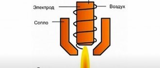
- Plasma cutting.
- Laser cutting.
The first technology, oxygen cutting, is used to separate carbon and low-alloy steel workpieces. In addition, an oxygen cutter can be used to trim the edges of already cut workpieces, prepare the joint interface area before welding, and “clean up” the surface of the cast part. The consumption of working gases, in this case, is determined by the consumption of both fuel (combustible gas) and oxidizer (oxygen).
The second technology – plasma cutting – is used for separating steels of all types (from structural to high-alloy), non-ferrous metals and their alloys. There are no materials out of reach for a plasma cutter – it cuts even the most refractory metals.
Moreover, the quality of the cutting seam, in this case, is significantly higher than that of competing technology. When determining the volumes of working gases, in this case, oxygen consumption is important - when cutting metal with plasma, it is the oxidizer that is responsible for the combustion of the material. And the plasma itself is used as a catalyst for the process of thermal oxidation of the metal.
The third technology, laser cutting, is used to separate thin-sheet workpieces. Accordingly, the volumes of consumed gases, in this case, will be significantly less than in oxygen and plasma cutting, which are designed to work with large, thick-walled workpieces.
Calculation standards for flammable gases and oxidizer
The consumption rates of propane and oxygen or acetylene and oxygen or only the oxidizer are calculated as follows:
- The standard fuel or oxidizer consumption per linear meter of cut ( H ) is multiplied by the length of the cutting seam ( L ).
- After this, the product of the same consumption standard ( H ) by the loss coefficient ( k ) associated with purging and setting the cutter is added to the resulting amount.
As a result, the oxygen consumption during welding (or the consumption of flammable gas) is calculated according to the formula:
Moreover, the coefficient k is taken equal to 1.1 (for small-scale production or piece cutting, when it is necessary to frequently turn the cutter on and off) or 1.05 (for large-scale production, when the cutter works almost without interruption).
Determination of gas consumption standards
To accurately determine the volume of gases consumed, it is necessary to determine the basis of the formula - the norm that determines the gas consumption per linear meter of the metal being cut, denoted in the formula by the letter “ H ”.
According to general recommendations, the normalized flow rate is equal to the quotient of the permissible flow rate of the separating apparatus ( p ) (oxygen, plasma or laser cutter) and the metal cutting speed ( V ).
That is, the formula by which the normalized oxygen consumption for cutting metal is calculated ( H ), as well as any other gas participating in the process of thermal separation, is as follows:
The desired result is substituted into the first formula and the specific value of the consumed volume is obtained.
Table of oxygen consumption when cutting pipes
| Pipe (outer diameter × wall thickness), mm | Oxygen consumption, m3 |
| Ø 14 × 2.0 | 0,00348 |
| Ø 16 × 3.5 | 0,00564 |
| Ø 20 × 2.5 | 0,00566 |
| Ø 32 × 3.0 | 0,0102 |
| Ø 45 × 3.0 | 0,0143 |
| Ø 57 × 6.0 | 0,0344 |
| Ø 76 × 8.0 | 0,0377 |
| Ø 89 × 6.0 | 0,0473 |
| Ø 108 × 6.0 | 0,0574 |
| Ø 114 × 6.0 | 0,0605 |
| Ø 133 × 6.0 | 0,0705 |
| Ø 159 × 8.0 | 0,119 |
| Ø 219 × 12.0 | 0,213 |
| Ø 426 × 10.0 | 0,351 |
| Ø 530 × 10.0 | 0,436 |
Determination of permissible flow rate and cutting speed
p (allowable flow rate) and V (cutting speed) used in the second formula
In particular, the value of the permissible flow rate is determined by the passport data of the welding machine. Essentially, p is equal to the maximum throughput of the cutter nozzle in operating mode.
But the cutting speed - V - is determined based on the depth of the seam, the width of the cutting jet of oxidizer or plasma, the type of material being separated and a whole series of indirect parameters.
As a result, the value of the permissible flow rate is extracted from the “cutter” passport, and the cutting speed is found in reference books that contain special tables or diagrams that connect all the input data.
And according to reference data, the permissible oxygen consumption is 0.6-25 cubic meters per hour. And the maximum cutting speed is 5-420 m/hour. Moreover, laser cutting is characterized by a minimum flow rate (0.6 m3/hour) and a maximum speed (420 m/hour): after all, such a cutter will only cut a 20-mm workpiece.
But a plasma cutter “burns” up to 25 m3/hour of oxygen and 1.2 m3/hour of acetylene. At the same time, it separates even 30-centimeter workpieces, making a cut at a speed of 5 meters per hour.
In a word, in such calculations everything is relative: the greater the speed, the shallower the depth and the greater the flow rate, the lower the speed.
source
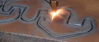
How metal is cut with gas
The most common method for cutting metal today is autogenous, also called gas or oxygen. Its essence boils down to the fact that under the influence of a gas flame, the metal heats up and begins to melt, and under the influence of a stream of oxygen it burns, making a narrow groove.
Acetylene, propane-butane, natural and coke oven gas are used as a heater.
Surface gas cutting is used in cases where it is necessary to remove layers of metal to form splines, grooves and other structural elements.
The dividing type involves making a through cut to obtain the required number of metal elements and parts. Burning through metal to create deep or through holes is called spearing.
Table of cutting thicknesses and gas consumption for NX type mouthpiecesThis results in a cut. Oxygen is supplied under high pressure, often reaching 12 atmospheres; such a jet, even without fire, can cut the skin.
The structure of the cutting apparatus is designed as follows:
- gas-burner;
- two cylinders;
- mixer;
- pressure regulator;
- hoses.
A gas burner consists of a head with several nozzles, usually three are enough. A flammable substance is supplied through two side ones, and oxygen is supplied through the third, which is located in the middle. The cylinders are designed directly for gas and oxygen; depending on the volume of intended work, cylinders of appropriate capacity are selected.
Gas-burner
To ensure one hour of continuous operation, an average of 0.7 m3 of acetylene (1 m3 of propane) and 10 m3 of oxygen will be consumed. In general, the required amount of feedstock will depend on the density of the metal and the required temperature to heat it. Propane consumption can be reduced by using special nozzle attachments that fix the gas supply in a certain direction; the closer the supply is to the oxygen stream, the higher the fuel consumption.
Hoses are necessary for supplying oxygen and flammable substances from cylinders to the mixer; they are also called hoses. The material from which the hoses are made is two-layer rubber, between the layers there is a frame made of cotton thread.
Diameter – up to 12 mm, possibility of operation at air temperatures not lower than -35 °C.
A pressure regulator is necessary to provide different cutting modes and speeds.
By supplying less fuel, it is possible to ensure the low temperature required for thin steel or low-strength metal, and also reduce the consumption of raw materials.
Another important function of the reducer is to maintain a uniform pressure level. If the gas supply is interrupted during the cutting process, the metal will quickly cool and further processing will become impossible.
Metal cutting with propane and oxygen
Necessary equipment
Cutter P101
The very first cutter was the P1-01 device, it was designed back in the USSR, then more modernized models appeared - P2 and P3. The devices differ in the size of the nozzles and the power of the gearbox. More modern manual settings:
- Change;
- Quicky;
- Orbit;
- Secator.
They differ in their range of additional functions and performance.
Quicky-E can carry out shape cutting according to specified drawings, the operating speed reaches 1000 mm per minute, the maximum permissible metal thickness is up to 100 mm. The device has a set of removable nozzles to ensure processing of metal sheets or pipes of various thicknesses.
Autogenous cutting machine Messer
This device can operate using various types of flammable gas, unlike the prototype P1-01, which runs only on acetylene.
The Secator manual cutter has improved characteristics compared to its analogues.
Cutter R2-01
With its help, you can process metal up to 300 mm thick, this is provided by additional attachments included in the kit, they are removable and can be purchased additionally as they wear out. Secator can produce the following types of cutting:
- curly;
- straight;
- ring;
- under the bevel.
The speed can be adjusted in the range from 100 to 1200 mm per minute, and the built-in freewheel ensures smooth movement of the machine along the sheet metal. The air-cooled gearbox ensures cleaner operation and reduces fuel consumption.
The above models are manual, that is, they are compact and controlled by the hands of a master. But for large volumes of processed metal, working with such
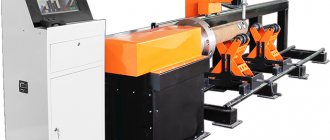
Stationary cutting unit
installations are inconvenient and ineffective. For industrial production, stationary cutting installations are used - this is essentially the same technology.
They are a machine with a table top into which a cutting mechanism is built. Its operation is ensured by electric
a compressor that requires an electrical network with at least 380 V and three-phase sockets. The technology of operation of models of stationary cutting units is in no way different from manual ones. The only difference is in productivity, maximum heating temperature, and the ability to process metal with a thickness of more than 300 mm.
Conditions for cutting metal with gas
Gas cutting of metal will be effective only when the ignition temperature of the metal is lower than the melting point. Such proportions are observed in low-carbon alloys; they melt at 1500 °C, and the ignition process occurs at 1300 °C.
For high-quality operation of the installation, it is necessary to ensure a constant supply of gas, since oxygen requires a constant amount of heat, which is maintained mainly (70%) by the combustion of metal and only 30% is provided by the gas flame.
If it is stopped, the metal will stop producing heat and oxygen will not be able to perform its functions.
Cutter operation, metal cutting training
The maximum temperature of hand-held gas cutters reaches 1300 °C, this is a sufficient value for processing most types of metal, however, there are those that begin to melt at particularly high temperatures, for example, aluminum oxide - 2050 °C (this is almost three times more than the melting point of pure aluminum), steel containing chromium – 2000 °C, nickel – 1985 °C.
Electrode consumption, norms, tables, how to calculate
Home page » About welding » Electrode consumption, standards, tables, how to calculate
An important part of any production or construction process is accurate and competent planning of material consumption, which is carried out to draw up estimates and calculate financial costs. When erecting metal structures by welding, it is important to know not only the metal consumption, but also the required number of electrodes. A correctly performed calculation will allow you to find out the exact cost of the work, and the welding process will be carried out according to plan.
It should be noted that calculating the consumption of welding electrodes is relevant and in demand only during the construction of large facilities . The large scale of work requires an accurate determination of the volume of materials, which will be included in the construction estimate. For this purpose, the concept of “electrode consumption per 1 ton of metal structures” was introduced.
Parameters affecting flow
Before calculating the number of electrodes for welding, you should find out which indicators are of utmost importance:
- Weight of material deposited on the connection. The volume of this parameter should not exceed 1.5% of the total mass of the entire structure.
- Duration and depth of the weld.
- Total mass of surfacing per 1 m.p. connections. Electrode consumption rates per 1 meter of seam are reference indicators presented in VSN 452-84.
- Welding type.
Theoretical and practical calculations
The consumption of electrodes can be calculated from a theoretical point of view using a large number of special formulas. Let's look at the most common ones.
The first method - by coefficient - is used to calculate the consumption of various welding materials, and not just electrodes:
H = M * K, where M is the mass of the structure being welded; K is a special flow coefficient from the directory, which varies in the range from 1.5 to 1.9.
The second method is based on calculations depending on the physical properties of the electrode and the metal structure . Allows you to determine the mass of deposited metal. Here the performer will need to know the reference data, and it is also necessary to measure the connecting seam:
G = F * L * M, where F is the cross-sectional area; L is the length of the weld; M is the mass of the wire (1 cm3).
Practical calculation involves carrying out test work. After their completion, the welder should perform the following actions:
- measure the cinder;
- take into account voltage and current;
- determine the length of the welded joint.
These data make it possible to determine the consumption of welding electrodes when welding structures with a seam of a certain length.
The contractor will be able to obtain accurate indicators only if the external data and the position angle during the main work are identical to those that were during testing. To avoid inaccuracy of parameters, it is recommended to carry out the experiment 3-4 times. This will allow you to obtain more accurate calculations than using theoretical formulas.
Using these methods, you can easily calculate the consumption of electrodes per ton of metal structures. However, you should remember that there is an error.
Gas welding and cutting technology
Gas manual welding is used to connect thin-walled (up to 3.5 mm)
steel pipes with a nominal diameter of up to 80
mm,
where electric arc welding cannot be used. The limited use of gas welding is explained by the fact that the mechanical properties of the weld in gas welding are lower than in electric arc welding. In gas welding, the deposited metal of the weld in the initial state has lower elongation and lower impact strength than the base metal.
Gas welding technology is that the edges of the parts being welded are heated by an oxygen gas flame and melted, the gap between them is filled with metal filler wire introduced into the heating zone. The gas flame melts an area 2.5-3 times the width of the depth. Penetration to a depth of more than 4-5 mm
difficult due to excess liquid metal.
Therefore, when welding pipes with a wall thickness of more than 4 mm
, bevel the edges. It is easier and faster to weld in the lower position of the seam. When gas welding carbon steel pipes, welding wire Sv-08A, Sv-08GA or Sv-08GS is used,
The process of oxygen cutting is based on the combustion of a certain volume of the metal being processed in a stream of oxygen and the removal of the resulting oxides (slags) by this stream. Oxygen cutting can be performed on metals whose ignition temperature in oxygen is lower than their melting point. To the greatest extent, this condition is satisfied by low-carbon steel, the ignition temperature of which is about 1350 ° C, and the melting point of 1500 ° C. Cast iron, most high-alloy steels and non-ferrous metals do not satisfy this condition.
Oxygen is supplied in steel cylinders, painted blue, with a capacity of 40 liters under a pressure of 150 kgf/cm 2.
The weight of the cylinder is 67
kg.
Acetylene is supplied in cylinders under a pressure of 16 kgf/cm 2,
or produced locally in acetylene generators from calcium carbide.
From 1 kg
of calcium carbide, 230-280 liters of acetylene are obtained.
The capacity of acetylene cylinders is 40 and 50 l,
diameter 219
mm,
weight 52 and 64
kg.
The cylinders are painted white with the inscription “acetylene”.
As flammable gases, in addition to acetylene, liquefied petroleum gases (propane-butane mixture), natural gas (methane), kerosene vapor, and gasoline are used (mainly for oxy-fuel cutting).
Mixtures of flammable gases with air and oxygen are explosive, so gas welding and cutting must be performed in well-ventilated areas.
Propane-butane mixtures are obtained as by-products during the extraction and processing of natural petroleum gases and oil. Mixtures of propane and butane are liquefied at low pressure (from 1 to 8 kgf/cm2).
They are stored and transported in thin-walled steel cylinders with a capacity of 40-55 liters at a pressure of up to 17
kgf/cm2.
When evaporating 1 kg
The liquid mixture produces about 500 liters of gas. The balloon is painted red.
Natural gases obtained from gas fields consist mainly of methane (up to 90% by volume) and admixtures of other gases. Natural gases are usually supplied to the place of consumption through gas pipelines, and are relatively rarely transported in red-painted cylinders.
For oxygen-acetylene welding and cutting, the following equipment is required: acetylene generators or acetylene cylinders, oxygen cylinders, pressure reducers, gas torches or cutters.
Acetylene generators are designed to produce acetylene from calcium carbide under the influence of water.
Gas welding torches are designed to mix oxygen and combustible gas in the required ratio and ensure the formation of a stable welding flame. According to the principle of operation, burners are classified into injection and non-injector. In table 10 provides general information about welding torches.
| Table 10 | |||||
| Characteristics of welding torches | |||||
| Burner name | Burner brand | Thickness of welded metal, mm | Tip numbers | Gas consumption, l/h | |
| acetylene | oxygen | ||||
| Oxy-acetylene injection | Moscow | Up to 30 | 0—7 | 20-280С | 22—3100 |
| Same | GS-53 and GS-57 | Up to 30 | 1—7 | 50—2800 | 55—3100 |
| » | GSM-53 | Up to 7 | 0—4 | 50—2800 | 50—3150 |
| Oxy-acetylene injection-free | GAR-1-58 | Up to 30 | 1—7 | 55—3600 | 50—2800 |
Cutters used for oxygen cutting differ from torches in the presence of a tube and a cutting oxygen valve, as well as a special head design. Cutters are classified according to the type of fuel (acetylene, for gases - acetylene substitutes, for liquid fuels) and according to the principle of operation (injector and non-injector). The most widely used universal acetylene-oxygen cutters RR-53, a. also plug-in oxygen acetylene cutters RGS-53 and RGM-53 for burners GS-53 and GSM-53. Insert cutters are especially convenient when performing installation and construction work, when relatively often they switch from welding to cutting and back.
In table 11 provides general information about cutters.
| Table 11 | ||||||
| Characteristics of cutters for oxygen cutting | ||||||
| Cutter name | Cutter brand | Thickness of cut steel, mm | Mouthpiece number | Gas consumption, m 3 / h | ||
| outdoor | internal | oxygen | acetylene | |||
| Oxyacetylene | RR-53 | 5—300 | 1-2 | 1—5 | 2,5-42 | 0,6-1,2 |
| Same plug-in | RGS-53 | 3—50 | 1 | 1,2 | 2-8,5 | 0,3—0,6 |
| » | RGM-53 | 3—30 | 1 | 1 | 2—5,8 | 0,3-0,55 |
| For acetylene substitutes | RZR-55 | 5—300 | 2 | 5 | 4,7—43 | Propane-butane mixture 0.4-0.7 |
Reducers are designed to reduce the gas pressure taken from the cylinder to the working pressure required for welding or cutting, and to maintain this pressure constant, regardless of the pressure in the cylinder and gas flow.
1. What metals can be oxy-cut?
2. Where is gas welding used?
3. What gases are used for gas cutting and welding of metals?
4. What colors are gas cylinders painted?
5. What main equipment is used for gas welding and metal cutting?
6. What types of torches and cutters are used?
All materials in the section “Pipe welding”:
Number of electrodes in 1 kg
After receiving ready data on the required number of electrodes, the welder proceeds to purchasing materials. Here another question arises: how many packages of consumables should be purchased. To do this, you need to determine how many rods make up 1 kg (standard pack). This indicator is influenced by all parameters of welding materials:
- diameter;
- rod length;
- rod weight;
- thickness of sealed packaging.
The larger these parameters, the fewer rods in the pack.
However, you should know that electrodes of a certain diameter have their own average mass:
| Electrode diameter | 2,5 | 3,0 | 4,0 | 5,0 |
| Weight, gram | 17,0 | 26,1 | 57,0 | 82,0 |
Fuel consumption standards for technology
| Type of technological operation | Fuel consumption |
| Cold blast cupola melting | Coke 110 - 160 kg per 1 ton of melted metal |
| Same with hot blast | Also 90-130 kg |
| Sand drying | Natural gas 25 - 40 MJ per 1 ton of dry ■ product |
| Drying clay | The same 50 - 80 MJ |
| Drying the rods | 10-15 MJ |
| Drying and heating ladles | The same 5 - 20 MJ per 1 ton of liquid metal |
The consumption of oxygen and acetylene is given in Table 38.
Table38
Oxygen and acetylene consumption
| Workshops | Purpose of the energy carrier | Expense for 1 t of suitable castings, m | |
| Oxygen Oxygen | Acetylene | ||
| Gray cast iron | Welding defects | 0,6 — 0,8 | 0,5-0,6 |
| Malleable iron | Same | 0,4 — 0,5 | 0,3-0,4 |
| Steel foundries | Profit cutting and welding defects | 3,0 — 4,0 | 1,5-2,0 |
Water is used for industrial and domestic needs. Water consumption is calculated for specific consumers, taking into account consumption, water quality, water recycling system and water losses due to evaporation.
Use water under pressure of 0.2 - 0.3 MPa. The average consumption of industrial water depending on the technological scheme of the process is given in table. 39. At the same time, up to 90% of recycled water supply is used.
Table39
How to calculate the consumption of electrodes per ton of metal
Calculation of the number of electrodes per 1 ton of metal is also carried out at the initial stage. This parameter is used for large-scale work, for large projects. The consumption rate of electrodes per ton of metal is the maximum cost of welding materials.
This indicator is calculated using the following formula, which determines the consumption using the mass of the metal:
H = M * K consumption, where M is the mass of the metal; K consumption - the table value is based on standard characteristics and depends on the brand of electrode.
Calculation of electrodes per 1 meter of seam: online and independently
Some websites on related topics provide the opportunity to make calculations using an online calculator. This method is simple and convenient. The performer will only need to enter the numbers in the appropriate windows, click the “calculate” button and automatically receive the finished result.
Welders can also perform calculations on their own. For this, the following general formula is used:
N = Nsv + Npr + Npr, where Nsv is the consumption of electrodes for welding; Npr - consumption of rods for tacks; Npr - consumption for straightening using the blank roller method.
The consumption rates of welding electrodes for tack work are determined as a percentage of the consumption for main work:
- The thickness of the walls of the structure is up to 12 mm. - 15%;
- over 12 mm. - 12%.
There are also standard standards that vary depending on the type of electrode and the thickness of the walls of the structure.
Depending on the consumption coefficient, according to the passport data, electrodes used in arc and combined welding of pipelines made of alloy and high-alloy steels are combined into 6 groups (Table 1). Group 1 includes electrodes with a flow coefficient of 1.4.
Electrode consumption coefficient
TsL-17, OZL-2, OZL-8, ZIO-8, OZL-6, OZL-7, OZL-3, OZL-21
OZL-9A, GS-1, TsT-15, TsL-11, UONI-13/NZh, TsL-9
Let's look at these standards using the example of connecting vertical seams of type C18:
| Wall thickness, mm. | Weight of deposited metal, kg. | Electrodes of group II, kg. | Electrodes of group III, kg. | Group IV electrodes, kg. | Group V electrodes, kg. | Electrodes of group VI, kg. |
| 3,0 | 0,201 | 0,366 | 0,390 | 0,415 | 0,439 | 0,464 |
| 4,0 | 0,249 | 0,453 | 0,484 | 0,514 | 0,544 | 0,574 |
| 5,0 | 0,330 | 0,600 | 0,640 | 0,680 | 0,720 | 0,760 |
| 6,0 | 0,474 | 0,861 | 0,918 | 0,975 | 1,033 | 1,090 |
| 8,0 | 0,651 | 1,182 | 1,261 | 1,341 | 1,419 | 1,498 |
| 10,0 | 0,885 | 1,607 | 1,714 | 1,821 | 1,928 | 2,035 |
| 12,0 | 1,166 | 2,116 | 2,257 | 2,398 | 2,539 | 2,680 |
| 15,0 | 1,893 | 3,436 | 3,665 | 3,894 | 4,123 | 4,352 |
| 16,0 | 2,081 | 3,778 | 4,030 | 4,281 | 4,533 | 4,785 |
| 18,0 | 2,297 | 4,532 | 4,834 | 5,136 | 5,438 | 5,740 |
Let's look at these standards using the example of connecting horizontal seams of type C18
| Wall thickness, mm. | Weight of deposited metal, kg. | Electrodes of group II, kg. | Electrodes of group III, kg. | Group IV electrodes, kg. | Group V electrodes, kg. | Electrodes of group VI, kg. |
| 3,0 | 0,152 | 0,269 | 0,286 | 0,305 | 0,322 | 0,340 |
| 4,0 | 0,207 | 0,368 | 0,393 | 0,417 | 0,442 | 0,466 |
| 5,0 | 0,262 | 0,465 | 0,497 | 0,527 | 0,588 | 0,590 |
Consumption of electrodes when welding pipes
The theoretical calculation is carried out using the following calculation method: the consumption rate per 1 meter of seam is divided by the weight of one electrode rod.
The calculation measure is the number of bars required. The resulting value is then multiplied by the footage. The result should be rounded up. To obtain the norm in kilograms, the following calculations must be made: the volume of a section 1 meter long is multiplied by the density of the metal. The first parameter should be defined as the volume of a cylinder with a diameter equal to the larger side of the joint. The resulting value must be increased by 1.4-1.8 times. This amendment takes into account cinders.
There are also standards for the consumption of electrodes when welding pipes based on the cost of welding one joint (when connecting horizontal joints of C8 type pipelines with a bevel of one edge):
| Pipe size, mm. | Weight of deposited metal, kg. | Electrodes of group II, kg. | Electrodes of group III, kg. | Group IV electrodes, kg. | Group V electrodes, kg. | Electrodes of group VI, kg. |
| 45Х3 | 0,021 | 0,037 | 0,040 | 0,042 | 0,044 | 0,047 |
| 45Х4 | 0,028 | 0,050 | 0,054 | 0,057 | 0,061 | 0,064 |
| 57Х3 | 0,027 | 0,047 | 0,060 | 0,054 | 0,067 | 0,060 |
| 57Х4 | 0,036 | 0,064 | 0,069 | 0,073 | 0,077 | 0,082 |
| 76Х5 | 0,061 | 0,108 | 0,116 | 0,123 | 0,130 | 0,137 |