Construction of a technological process for milling processing
Contents of the technological process.
At the final stage of training, a young worker, within the limits of his profession, must be able to independently develop a technological process, the level of technical literacy of which serves as one of the main indicators of the qualification maturity of a milling machine operator.
The work of constructing a technological process includes choosing a rational technological route, fixtures, tools, cutting modes and calculating the main time to complete each transition.
The technological route is developed on the basis of general rules and principles discussed in detail earlier, as well as information on the implementation of various operational milling operations. Devices, cutting and measuring tools are selected according to the accepted methods of installing workpieces on the machine, methods of surface treatment and the required accuracy. The type of production should be taken into account. In single and small-scale production, general purpose devices and tools are mainly used, provided for by the current standards and norms of mechanical engineering. Medium- and large-scale production is characterized by the use of universal-adjustment, universal-assembly and multi-place devices, special shaped cutters and rigid testing tools (plugs, staples, templates). In mass production, special equipment is used mainly for each technological operation. The cutting mode is prescribed based on the rules set out earlier.
Basic (machine) time To
, directly spent on the cutting process, is calculated (in minutes) for each transition according to the formula
where L is the estimated processing length, mm;
sm—minute feed, mm/min; k is the number of simultaneously processed workpieces; i is the number of passes. In turn, the estimated processing length
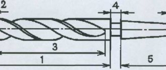
is defined as the sum (Fig. 174):
where l is the length of the machined surface in the feed direction, mm; l1 — cutter penetration value, mm; l2 is the amount of overrun of the cutter, mm.
The length of the plunge
is determined by the following formulas:
for cylindrical and disk cutters (Fig. 174, a)
for end mills during symmetrical milling (Fig. 174, b) for end mills during asymmetric milling (Fig. 174, c) for end mills when processing grooves and shoulders (Fig. 174, d) The
overtravel l2
is taken into account only when milling open surfaces and is accepted within 2...4 mm.
Design of the technological process.
In accordance with ESTD (GOST 3.1108-74), the completeness and forms of technological documentation are established depending on the type and nature of production. The main technological document for all types of production is the route map (GOST 3.1105-74), which for serial and mass production is supplemented by operational cards (GOST 3.1404-74), containing all the necessary information for carrying out technological operations. If necessary, sketch cards can be attached to the operational cards, in which explanatory sketches and processing and control diagrams are entered.
To develop the technological thinking of a young worker, it is advisable to use the educational form of a technological map (see Table 18), which includes all the basic information and illustrations for them from the above maps.
The rules for filling out columns 1...5 of the technological map, containing information about the technological route, were discussed earlier. In the “Device” column the names of the devices used are indicated. The “Tools” column lists the types of cutters, their material and main dimensions - diameter and number of teeth. When designating measuring instruments, you should use their standard name and markings given in reference books.
When entering cutting modes into the map, it is necessary to indicate the actual cutting speed, feed and rotation speed adopted for the machine.
The estimated processing length L is taken as a common value for all simultaneously processed workpieces and is determined by formula (60). The main time To is calculated using formula (59) for one part.
Let's consider a specific example of constructing a technological process for milling a guide plate (Table 18).
Initial data: part drawing; workpiece - forging of rectangular section 85x33x133 mm from steel 45; number of parts per batch—10 pcs.; machine - vertical milling model 6Р12П.
We begin the development of the technological process by constructing a technological route according to a logical diagram.
At the 1st stage, we will study the initial data.
Based on the drawing, we will determine the technical requirements for the accuracy of processing the part. The slab has two dovetail-shaped guide ledges, two shallow grooves 25 and 50 mm wide, a closed blind groove 14 mm wide and two 4x45° bevels. Sizes 14, 12 and 60 are limited by maximum deviations. The remaining dimensions without tolerances must satisfy the 14th quality: female - according to H14, male - according to H14.
The accuracy of the geometric shape is established by the drawing only for the main reference plane of the part and the surfaces of the guide steps, the non-flatness of which should not exceed 0.1 mm. Errors in the shape of other surfaces are conventionally accepted as no more than 1/2 of the tolerance of the corresponding size.
The accuracy of the relative position of the surfaces is specified in the drawing for the guide ledges. Their asymmetry to the side surfaces of the part and their nonparallelism to the main reference plane A should not exceed 0.2 and 0.1 mm, respectively.
The roughness (height of irregularities) indicated on the outline of the drawing is Rz=20 µm. Roughness of other surfaces is no more than Rz=80 microns.
The part is not subjected to heat treatment; therefore, its complete processing, taking into account low accuracy, can be performed on a milling machine. The material of the part is high-quality structural carbon steel, grade 45, with an annealed hardness of no more than HB197.
The dimensions of the workpiece provide sufficient allowance for processing - 2.5 mm per side.
The small size of the batch of parts (10 pieces) and their one-time production allow us to draw the conclusion about the need for a step-by-step construction of the technological process with a low degree of dissection.
The technical characteristics of the machine model 6Р12П with a rotating spindle head are given in the table given earlier. The mechanism for longitudinal movement of the machine table provides for adjustment of the gaps in the screw drive.
At the second stage of technological preparation, we select methods of surface treatment, technological bases and methods of installing workpieces on the machine.
In accordance with the general principle of maximum productivity and taking into account the type of machine, we will perform processing of dimensional planes with end mills; rectangular shoulders, grooves and bevels will be processed with end mills equipped with a hard alloy. To machine 60° guide shoulders and slots, angle and slotting cutters made of high-speed steel will be used, respectively.
Guided by the rules for selecting technological bases, we first process the workpiece with the largest surface area, which will later be used as the main base. To obtain the correct location of the guide ledges to the main base of the part, it is advisable to process them in one installation on the machine.
According to the selected bases, and also taking into account the small size and relatively simple shape of the part, we will install the workpieces on the machine in a rotary machine vice equipped with wedge-type overhead jaws.
At the third stage of constructing a technological route, we establish the number and content of operations.
Taking into account a small batch of processed parts and the general rules for completing operations, we divide the technological route into 12 operations, the contents of which are given in Table. 18.
We fill out the remaining columns of the technological map according to the previously stated rules. As an example, consider these actions for I-2 operations.
We fix the workpiece in a rotary machine vice with wedge jaws. The diameter of the end mill is determined by formula (7):
According to the standard, we select a cutter D=125 mm and z=8, equipped with T15K6 hard alloy.
To control the planes we use a ShTs-1 caliper, a measuring ruler and roughness samples.
We process the planes in one pass with a milling width of B=85 mm and a cutting depth of t=2.5 mm. The feed per tooth, taking into account the required roughness, is taken according to the table. 16: sz=0.12 mm/tooth. According to the table 17 and 18, we select the cutting speed taking into account correction factors: v = 280 * 1 * 1 * 0.85 = 238 m/min.
Calculate the required rotation speed
For the machine we take n = 630 rpm, which will correspond to the actual cutting speed: We enter these values of cutting speed and rotation speed into the technological map.
Determining the minute feed
For the machine we take sm = 630 mm/min.
We calculate the main time using formula (59):
To determine the design length L, we find the plunge length for asymmetrical face milling using formula (63): The amount of displacement of the cutter relative to the workpiece C is found from the equality Taking C = 6 mm, we obtain Then using formula (60): Finally
Milling with end mills
Milling with end mills is used for:
- processing of grooves, ledges;
- volume copying;
- shaped surface treatment;
- removing overhangs from panels lined with various materials;
- contour processing of parts;
- performing other operations.
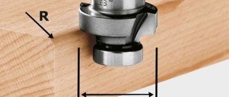
In this article we will talk in detail about end mills and technologies for processing shoulders, bevels, and grooves of various shapes.
Photo #1: Milling with an end mill
End milling equipment
Horizontal and vertical milling machines are used for milling with end mills. Tools are installed in cartridges of various designs.
Chucks for end mills with cylindrical shanks
End mills with cylindrical shanks are fixed using such chucks.
Image #8: Straight Shank End Mill Chuck
They consist of bodies (1), nuts (2) and cams (3). The housing is installed in the spindle and tightened with a cleaning rod. The cams clamp the tool using a ring (4) and intermediate springs.
Chucks for end mills with tapered shanks
They have this design.
Image #9: Chuck for end mills with tapered shanks
The housing (3) is secured in the machine spindle using a cleaning rod. The replaceable sleeve (4) has a screw (5) designed to secure the cutter. The bushing strips pass through the holes of the nut (2) screwed onto the body and are inserted into the grooves at the end. The position of the nut is adjusted using a special screw (6).
Important! Replacement bushings have standard sizes corresponding to Morse tapers.
Collet chucks
Designed for mounting end mills with cylindrical shanks.
Image #10: collet chuck
The conical shank of such a chuck is tightened in the machine spindle using a ramrod. There is a recess at the front. It includes a collet (1). This is a conical split bushing with a hole whose diameter corresponds to the diameter of the shank of the cutter being fixed. To fix it, the collet is compressed with a nut (2).
Chucks with adjustable eccentricities
They consist of bodies (1), cap nuts (3) and bushings (2).
Image #11: Chuck with adjustable eccentric
The sleeve in such a chuck is eccentrically fixed relative to the axis of the rotating cutter (4). It is secured with two screws (5). By turning the sleeve, the width of the groove is adjusted.
Metal milling technology: up and down milling
To process materials, milling methods are used that differ in the direction of supply of the material used. As a rule, when roughing primary finishing of metal or hard alloy workpieces, counter milling is most often used. With soft metals and during semi-finishing or finishing processing, it is better to work using the passing method. In addition to the application features, these methods of work have their own advantages and disadvantages that determine their relevance.
Associated technology
In the process of using down milling, the cutting equipment rotates in the same direction in which the workpiece arrives, which determines a number of advantages of this method:
- under the influence of inertial forces, the workpiece is firmly held on the frame, so there is no need for its strong fixation to the table, which reduces the likelihood of material deformation;
- the allowance is removed with maximum smoothness, due to which only slight roughness is formed on the surface;
- the cutting edge of the cutter has slight wear, since during parallel movement they become dull at a lower speed;
- quick removal of chips without the use of additional tools or devices.
But, in addition to its advantages, this technology also has a number of disadvantages. Climb milling is not suitable for working with metals with many solid inclusions; it requires preliminary preparation of rough surfaces and is accompanied by strong vibrations, which can only be eliminated by using a machine with high rigidity.
Up milling
Unlike down milling, up milling involves directing the cutting tool to meet the movement of the workpiece. Thanks to this, it is possible not only to increase productivity, but also to obtain other advantages:
- minimal load on the mechanism, thereby extending its working life;
- a soft and uniform effect on the metal during the cutting process, allowing you to gradually increase the depth of cut without deviating from the permissible dimensions;
- absence of vibrations, even when processing metal with a rough, rough surface.
The disadvantages of counter milling include the fact that the workpiece needs to be securely fixed, since the cutting force is partially aimed at tearing the template away from the bed. In addition, the disadvantage is the rapid wear of the cutter and the fact that chips are poorly discharged and can fall into the cutting zone.
Milling inclined planes with cylindrical end mills
Two technologies are used for milling inclined planes with end mills.
Milling with workpiece rotation
This technology involves the use of a universal rotary vice. The blanks are fastened in them in the same way as in regular ones.
Image No. 15: milling an inclined plane with an end mill and rotating the workpiece
Important! The inclined plane to be processed should be parallel to the table.
Milling with machine spindle rotation
This is possible on both vertical and horizontal milling machines. To do this, the former must have the function of rotating the headstock with the spindle around a horizontal axis, and the latter must have overhead vertical heads. For milling, simply set the desired angles of inclination.
Image #16: Milling an inclined plane with a 60° end mill
Contact us
Rosta LLC offers metal band sawing machines at prices 1.5 - 2 times lower than analogues from foreign manufacturers,
with the same quality and reliability. Automatic, semi-automatic and manual options are available. Our machines will allow you to solve even the most complex problems of any enterprise. To leave a request or clarify the information you are interested in, call: (473) 239-65-79;, and the managers of Rosta LLC will provide all the information you are interested in.
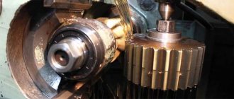
Milling inclined planes with angular end mills
Performed on horizontal milling machines. Processing of workpieces with corner cutters occurs at lower feed and cutting speeds. This is due to difficult working conditions.
For example, with a milling depth of 12 mm, a cutting speed of 11.8 m/min is prescribed. Spindle rotation frequency - 50 rpm.
Image #17: Milling an inclined plane with a miter end mill
Note! To avoid defects when milling an inclined plane:
- Before the operation, make sure the markings are accurate;
- secure the workpiece as securely as possible;
- thoroughly clean the vice and table from shavings;
- Check the angle of the tool or universal vice.
Milling through slots with end mills
To mill through grooves, end mills are usually used, the diameters of which correspond to the drawing dimensions of the grooves with permissible deviations.
Important! This is done in cases where the end mills do not have radial runout. If it is present, the width of the groove will be greater than the specified one. The result is marriage.
To machine through grooves, new end mills are most often used. When working with sharpened tools, chucks with adjustable eccentrics can be used to maintain the accuracy of the grooves. The technology for milling through grooves does not differ from that described above.
Contour milling with end mills
There are two main technologies for contour milling with end mills.
With a combination of manual feeds
The technology looks like this.
- The workpiece is fixed on a table or in a vice.
- The part is processed with an end mill along the marked contour (the table moves in the longitudinal and transverse directions).
Note! It is impossible to mill a contour in one go. The part is first rough-processed and then finished.
Image No. 21: milling a curved contour with a combination of manual feeds
Using a round turntable
When milling workpieces on round rotary tables, the contours of the arcs are formed due to their circular feeds. Devices can be manual or mechanical. Using this technology, high-precision contours are obtained.
Image #22: Round rotary table with manual feed
Note! Above we examined only the main areas of application of end mills. Read about other operations and the peculiarities of their implementation in specialized literature.
Metal milling stages
The quality of metal products or other materials produced during the milling process depends not only on the workpiece, but also on compliance with the technology, which includes certain stages:
- Preparation for work, during which the cutting tool is installed on the spindle and the workpiece is fixed on the work table of the machine tool.
- Setting operating parameters - the depth of material cutting in one pass, the rotation speed of the cutting equipment, the direction of movement of the workpiece and the degree of smoothness of its feeding.
- Starting the rotation of the cutting part at low speed to slightly touch the cutter with the material being processed. This allows you to check the correct depth of cut and the safety of the process, after which the spindle is retracted to its original position and, if necessary, the performance characteristics are adjusted.
- Restarting the electric motor, starting the feed of the workpiece and carrying out the milling process with constant monitoring of the criteria of the part being formed.