Hole drilling techniques
Before drilling a hole, it should be centered with a short spiral drill of larger diameter (Fig. 125, a) or a special centering drill (Fig. 125, b). The tip angle of this drill should be 90°. Under this condition, at the beginning of drilling, the transverse edge of the drill does not work (Fig. 125, c), which contributes to less movement of the drill from the correct position.
If for some reason centering cannot be done, do this. The tip of the drill of the same diameter as the hole is brought almost close to the rotating part. Then they bring the cutter (any) as close as possible to the top of the drill, fixed in the tool holder so that the head of the cutter is facing the turner, and only after that they begin to deepen the drill into the part. This technique helps to some extent prevent the drill from moving at the beginning of work. As soon as the drill goes a little deeper, the cutter supporting it must be moved to the side.
Rice. 125. Drills (a, b) for centering holes drilled on a lathe, and the initial position (c) of the working drill in a centered cone
The drill is fed on lathes, as a rule, manually by turning the tailstock quill handwheel. However, on machines of modern models (for example, 1K62) there are devices for coupling the tailstock with the support carriage, which greatly facilitates the turner’s work. Of course, it is advisable to use this device mainly for drilling holes of relatively large diameter and long length, especially when manufacturing parts in large quantities.
If the depth of the hole being drilled is greater than its diameter, then from time to time you should remove the drill from the hole and remove chips both from the hole and from the grooves of the drill. The hole in steel parts is cleaned by washing it with coolant (for example, using a syringe), and in cast iron parts by blowing it with air using the same syringe or a jet of compressed air.
You must be especially careful when the depth of the hole being drilled is greater than the length of the working part of the drill. In fact, if the entire helical groove of the drill ends up in the hole, then the chips generated during drilling will have no outlet, will fill the grooves and the drill will break. If it is necessary to stop the machine while the drill is in the hole being drilled, you should first remove the drill from the hole, and only then stop the machine .
Cutting modes when drilling. The feed when drilling holes on lathes, if it is done manually, should be as uniform as possible.
When through drilling, at the moment when the transverse edge of the drill leaves the metal, the force required to carry out the feed decreases sharply. Therefore, with the same pressure on the tailstock handwheel handle at which drilling , the drill feed increases, as a result of which the drill often breaks. To avoid breakage, the feed of the drill before it leaves the metal should be as small as possible. When drilling using automatic feed, the latter must be turned off in a timely manner, before the tip of the drill approaches the exit from the metal.
For a general idea of the feed rates, we can assume that when drilling holes with a diameter of 5-30 mm in steel parts with automatic feed, the feed is taken in the range of 0.1-0.3 mm/rev, and for cast iron parts - in the range of 0.2- 0.7 mm/rev. The cutting speed when working with a high-speed steel drill should be about 30 m/min if the material of the workpiece is medium-hard structural steel and about 35 m/min if the part is made of medium-hard cast iron.
Cooling during drilling lowers the temperature of the drill, which is heated by the heat of cutting and friction against the walls of the hole, reduces the friction of the drill against these walls and, finally, promotes chip removal. An emulsion is used as a coolant when drilling holes in steel parts. Drilling holes in cast iron is done without cooling.
Accuracy and surface roughness obtained during drilling. The diameter of the hole being drilled is slightly larger than the diameter of the drill. This is explained by the fact that the drill moves away from the axis of the hole even with minor errors made when sharpening the drill and installing it on the machine, as well as with uneven hardness of the material being processed. Experience shows that by drilling holes with a diameter of up to 10 mm, the 4th class of accuracy is achieved, and for larger diameters - the 5th class of accuracy. With careful work (proper sharpening of the drill and its installation on the machine), class 4 accuracy can be achieved when drilling holes with a diameter of up to 30 mm. The surface roughness obtained by the drill does not exceed V 4.
Drilling holes. When drilling large-diameter holes, the feed force may be excessively large and its implementation will be tiring for the worker. Sometimes when working with such drills, the power of the machine may be insufficient. In such cases, the hole is formed sequentially with two drills of different diameters, the ratio of which should be such that the diameter of the first drill is greater than the length of the transverse edge of the second drill. Under this condition, the transverse edge of the second drill does not participate in cutting, as a result of which the force required to carry out the feed is significantly reduced and, which is very important, the drift of the drill away from the axis of the hole being machined is reduced.
In practice, it is customary to take the diameter of the first drill equal to about half of the second, which ensures favorable conditions for wear of the drill and uniform distribution of the feed force when both drills are working.
The feeds when drilling can be taken slightly larger than those indicated above for drilling, and the cutting speeds are approximately the same as when drilling.
Preparation for drilling
Important conditions for high-quality turning of a hole with a drill: strong fastening of the workpiece without noticeable runout, perpendicularity of its end to the axis of rotation, absence of irregularities and convexity at the end, coincidence of the quill axis with the spindle axis, giving the original direction to the drill.
The workpiece installed in the lathe chuck is, if necessary, aligned and firmly secured. Its end is trimmed cleanly before drilling. To give the initial direction to the drill, especially if it is long, it is recommended to make a small conical recess in the center of the end. It is performed with a persistent cutter (Fig. 56, a) or a short rigid drill (Fig. 56, b). The angle of the center recess is made 20-30° less than the angle at the top of the working drill. Under this condition, the drill bridge will not participate in cutting at the initial moment (Fig. 56, b), which greatly reduces the risk of the drill moving to the side.
READ How to sharpen a chainsaw chain with an electric machine
To increase the rigidity of long drills, it is recommended to support them at the beginning of drilling with the back of the cutter, fixed in the tool holder slightly above the center axis.
Before drilling a deep hole, the workpiece should first be drilled with a short drill of the same diameter to a depth approximately equal to the diameter of the hole. In this case, the main drill, having received its original direction, will not be able to deviate to the side.
Proper installation of the drill is equally important. Its shank and hole should be wiped dry, and the nicks on the shank should be removed with a file. The drill is installed into the quill with a sharp axial push.
Drilling techniques
The following method of drilling on a lathe is usually used. After the preparatory work, turn on the spindle and manually turn the tailstock handwheel to bring the drill to the end of the rotating workpiece. In this case, you should avoid impact, otherwise the drill may break. At first, the drill is fed forward slowly, but when it cuts into the metal to a depth slightly greater than the length of the cutting part, the feed can be increased. The drill feed should be performed smoothly, without jerking.
Particular care should be taken when the drill comes out of a through hole. In this place, an uneven load on the cutting edges occurs and they can crumble. Therefore, at the output, the supply must be sharply reduced.
Before turning off the spindle rotation, the drill must be removed from the hole, otherwise due to elastic deformation of the metal it may jam in the hole.
When drilling, chips are difficult to come out of the holes, so the drill must be periodically cleaned with a wire brush.
The depth of the blind hole is maintained according to the millimeter scale of the quill, according to the dial of the tailstock flywheel, and in their absence - according to the chalk mark, which is applied to the drill.
To increase the durability of the drill, it is recommended to cool it. Steel is drilled using an emulsion, non-ferrous metals are drilled with cooling or dry, cast iron is drilled without cooling. A jet of coolant is directed to the drill near the end of the workpiece and is turned on simultaneously with the start of cutting.
Manually feeding the drill, especially when machining large-diameter holes, is too difficult. Therefore, a number of models of modern lathes provide a device for mechanical movement of the tailstock. It represents a castle. which consists of two squares, respectively attached to the cross slide of the caliper and the tailstock plate. Before turning on the mechanical feed, the tailstock is detached from the bed.
Drilling holes
Drilling large diameter holes is very difficult due to the significant feed force. Therefore, holes with a diameter of over 30 mm are made with two drills. The diameter of the first of them is taken to be approximately ½ the diameter of the hole. Thanks to this, the bridge of the second drill is not involved in cutting, the feed force is greatly reduced and the likelihood of the drill moving to the side is reduced. The drilling techniques are the same as for drilling.
Cutting modes for drilling and reaming
The depth of cut t when drilling is characterized by the size of the drill and is equal to ½ of its diameter. When drilling, it is determined by the half-difference in hole diameters after and before processing.
The feed S during drilling and reaming corresponds to the axial movement of the drill per revolution of the workpiece and is expressed in mm/rev.
The cutting speed v for a non-rotating drill is equal to the peripheral rotation speed of the machined hole surface in m/min.
Feeding the drill on lathes is most often done manually. When working with mechanical feed for holes with a diameter of 5 to 30 mm in steel workpieces, it can be selected within the range of 0.1–0.4 mm/rev. Large feeds within the specified limits are accepted for drills of larger diameter. When drilling cast iron, the feed rate can be increased by approximately 1.5 times; the same goes for drilling holes.
The cutting speed for high-speed drills when machining holes in steel and cast iron workpieces is selected within the range of 20–40 m/min; for drills equipped with carbide inserts, it can be increased by 2-3 times. For drills of smaller diameter, higher cutting speeds are used.
Deep Hole Machining
In case of making deep holes, it is necessary to perform all preparatory operations in the same sequence as usual:
- Setting the alignment of the tailstock and spindle.
- Securing the workpiece.
- Preparation and installation of cutting tools.
- Trimming the workpiece.
- Making a recess at the end of the workpiece.
In this case, you need to adhere to several recommendations:
- Deep drilling should be started with a short tool to a depth equal to the diameter of the drill, and then changed to the main one. This will help prevent the main drill from deviating from the desired direction.
- At the beginning of cutting, to increase the rigidity of a long drill, it is supported from the side with the back side of the cutter fixed in the tool holder.
Deep drilling causes significant thermal and mechanical loads on the cutting tool due to the larger area of rubbing surfaces. Therefore, it is necessary to pay more attention to cooling and timely removal of chips from the cutting zone.
Features of CNC machines
When working on lathes, CNC (computer numerical control) can be used. This only provides advantages when producing large quantities of products. Since debugging and setting up such machines takes a lot of time, it requires the creation of special programs and the presence of a qualified operator-setter.
Advantages of using CNC machines:
- Freeing the operator (turner) from any calculations.
- The accuracy of parts processing increases.
- The human factor is minimized.
- Increased labor safety.
- Increased labor productivity.
- Possibility of working around the clock and seven days a week.
- Reduces unit production costs.
Drilling holes
Holes in solid metal are formed by drilling. Drilling and reaming on lathes are mainly used as a pre-processing method.
Drilling is carried out with a rotating workpiece and less often with a rotating drill fixed in the machine spindle
Drilling holes ensures hole dimensional accuracy up to 12th grade and roughness up to 3-4th grade. Drilling increases the diameter of a previously drilled hole and, under certain conditions, increases its accuracy by approximately one grade.
The metal turning under consideration is performed on lathes, and spiral drills are mainly used as cutting tools.
A twist drill is a two-tooth cutting tool consisting of a working part, a neck and a shank. The working part includes cutting and guiding parts.
Installing drills on the machine
Drilling on a lathe is done with a non-rotating drill, which is fixed in the tailstock quill.
Drills with a conical shank are installed directly into hole , if their dimensions are the same, or using an adapter sleeve 2 placed on the drill shank 1.
Drills with a cylindrical shank are fixed on the machine using drill chucks, one of the designs of which is shown in Fig. 55, a. In the inclined holes of the housing 3, cams 4 are installed in the form of cylindrical rods with bevels for fastening the drill and a threaded part on the outer surface. Inside coupling 5 there is a nut with a conical thread, which connects to the threads of the cams. If you rotate the clutch with key 2, the cams, moving in the inclined holes, will compress, ensuring the fastening and centering of the drill. Housing 8 on the reverse side has a blind conical hole , with which it is firmly mounted on shank 1. Such chucks are available in three sizes: PS-6, PS-9, PS-16 (the numbers indicate the largest diameter of the drill being fixed).
If you need to frequently change tools installed in the tailstock, it is convenient to use quick-change chucks (Fig. 55, b). The cartridge consists of a body 2 with a conical shank 6 and two holes in which balls 3 are loosely rolled. An adapter sleeve 1 with a Morse conical hole is installed in the body. There are two radial grooves on the outer surface of the bushing, into which balls fall during the working position of the cartridge. A coupling 4 is loosely mounted on the body, the longitudinal position of which is limited by spring rings 7 and 9 and a spring-loaded ball 5, which secures the coupling in working condition. Hole 5 is provided for air outlet when installing the adapter sleeve into the cartridge.
READ Cordless Screwdriver You Can Do A Little Wrong With!
The action of the chuck is as follows: The required drill is inserted into the adapter sleeve and together with it is installed in the chuck. The clutch is shifted to the right. Then, when moving to the left, the clutch presses on the balls, which fit into the recesses of the sleeve and secure it. To change the tool, just move the coupling to the right, and the sleeve with the drill can be freely removed from the chuck.
For drilling with mechanical feed, a simple device is sometimes used in the form of a bushing with a rectangular protrusion, with which it is secured in the caliper tool holder.
When deep drilling, it becomes necessary to frequently remove the drill from the hole to clear chips. In this case, the time for retracting the drill and returning it to its original position can be significantly reduced by using a fairly simple chuck (Figure 55, c). It consists of a body 2 with a conical shank, a drill holder 1 with a handle 3 screwed into it. The body has an oblong groove with a number of transverse grooves. To retract the drill, simply remove the handle from the groove and move the drill to the right. Returning the drill to the working position is performed in the reverse order.
Rotate the upper support carriage.
When processing conical surfaces, the carriage of the upper support is rotated at an angle equal to half the angle at the apex of the cone being processed. Process with manual feed of the upper support at an angle to the mowing line of the center of the machine (a). In this way, conical surfaces are ground, the length of the generatrix of which does not exceed the stroke of the upper support carriage. Any cone angle of the surface being machined.
Methods for making holes on lathes
Requirements for processing cylindrical surfaces
Main types of turning work
Requirements for processing cylindrical surfaces
Methods for making holes on lathes
Methods for obtaining conical surfaces
Various machine parts, such as shafts, gears, axles, pins, rods, pistons, have external cylindrical surfaces.
The following requirements are imposed on cylindrical surfaces: straightness of the generatrix;
cylindricity: in any section perpendicular to the axis, the circles must be of the same diameter (there should be no cone-shaped, barrel-shaped, saddle-shaped);
roundness: any section must have the shape of a regular circle (there should be no ovality or cutting); coaxiality: the location of the axes of all steps of stepped parts on a common straight line.
It is impossible to absolutely accurately meet the requirements for cylindrical surfaces: even with the most careful manufacturing, some errors will arise.
Permissible deviations in the shape and location of surfaces are indicated on the drawings of parts with symbols or text in accordance with the Unified System of Design Documentation (ESKD, GOST 2.308-68).
To control the accuracy of the diameters of the outer cylindrical surfaces, various measuring instruments are used. Control with an accuracy of 0.1 mm is carried out using a ShTs-1 caliper ,
and with an accuracy of 0.05 mm - with a ShTs-P caliper.
For measurements with an accuracy of 0.01 mm, micrometers with measurement limits of 0 to 25 are used; 25 to 50; 50 to 75; 75 to l00; 100 to 150; 150 to 200; 200 to 300 mm. Precise measurements of external surfaces (up to 0.01 mm) are also made using an indicator bracket ,
which is pre-adjusted to the nominal size using measuring tiles. When taking measurements, the indicator arrow shows on the scale the deviation from the nominal size. In the production of large batches of parts, the diameters of the outer cylindrical surfaces are controlled by limit gauges. The size is considered correct if the pass side of the PR bracket fits freely onto the surface being measured, but the non-pass side does not fit.
Drilling . The cutting tools are drills, which by design are feather, spiral, centering and weapon (gun) drills. Feather drills are described in
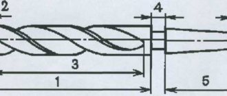
A twist drill consists of a working part, a shank, a neck, a foot or a leader. On the side surface of the working part there are two helical (spiral) grooves, forming cutting edges and creating space for chips to exit. The shank is used for fastening, and the foot is used for knocking out the drill. The foot, in addition, does not allow the drill to rotate. As a rule, data on the size and material of the working part is stamped on the necks or on the cylindrical shanks of drills.
The drilling process involves the separation of metal particles under the action of cutting forces and the formation of holes during the rotational and translational movement of the drill or workpiece. Such movements of the drill or workpiece are provided either by machines or by a mechanic using a brace, ratchet or drill.
The crankshaft is a steel bracket bent to resemble a crankshaft. The middle link serves as a handle for rotating the brace, the upper link has a cap for pressing the brace to give the drill a forward motion, and the lower link is equipped with a chuck or socket for attaching the drill. Rotators are used mainly in the processing of non-metallic structural materials
A hand drill (Fig. 101, a) consists of a frame with a stop / for pressing the drill and giving the drill forward motion, a two-stage multiplier 2 (accelerator) with a manual drive 3
and a chuck for attaching the drill.
The ratchet (Fig. 101, c) is used only in hard-to-reach places and for drilling relatively large holes when it is impossible to use a drill.
A -
hand drill with two-stage transmission (/ - stop;
2 -
two-stage multiplier;
3
- drive with handle;
4
- chuck; 5 - drill);
b - hand drill with an open single-stage (bevel) gear; i - ratchet (6 - stop; 7 -
nut;
8
- fork handle that rotates spindle
9
and ratchet wheel
10; II -
pawl;
12 -
pawl spring).
You can drill holes according to the markings using a template and through a jig. In the latter case, labor productivity increases. In this regard, the section discusses issues of manufacturing conductors and other devices. However, it must be borne in mind that the production of equipment (conductors, templates) is economically justified only in mass or large-scale production. Therefore, it is necessary to carefully study the less productive method - drilling according to the markings.
This method of processing holes usually does not provide the necessary accuracy and surface roughness. Therefore, after drilling, the walls of the hole are often additionally processed, thereby increasing the surface quality and accuracy.
Reaming is a small increase in the diameter of a pre-drilled hole. Perform with a larger twist drill. Reaming also provides greater center-to-center accuracy.
- end countersink (cecocca); g—scan; / - shanks; 2 —
working part;
3 -
necks;
4 -
lanks.
Countersinking - processing in castings and forgings, as well as pre-drilled holes with an allowance for finishing to eliminate or reduce ovality, taper and other defects. Sinking can be a process of finishing holes and preparing them for reaming.
READ How to Sharpen a Chainsaw Chain on a Machine
Countersinking - chamfering holes, producing conical and cylindrical pieces of smaller diameter.
They countersink and countersink with a cutting tool - a countersink. There are cylindrical, conical and face countersinks. The last two are sometimes called countersinks, and the face countersinking operation is called non-forging. Countersink - a rod made of steel grades U10 and U12 with cutting edges on the side cylindrical or conical surface (cylindrical and conical countersinks), as well as with teeth located at the end (end). To ensure alignment of the previously drilled hole and the countersink, a smooth guide cylindrical part is often made at the end of the latter.
Reaming - finishing (final) finishing of holes (not counting possible abrasive processing) using a reamer (Fig. 102, d). It consists of a working part, a neck and a shank. The cutting teeth are located on the conical (taking, cutting part) and cylindrical surfaces (calibrating part), along the reamer axis. There are no teeth at the end of the reamer. The teeth around the circle can be distributed evenly or unevenly. The latter is more common in reamers intended for manual work (for example, the angles between the teeth are
Wide turning cutters.
They grind short conical surfaces with a generatrix length of up to 30 mm using turning cutters. Grind with transverse or longitudinal feed. This method can be used when chamfering machined cylindrical surfaces.
Drilling
Drills with conical shanks are installed directly into the conical hole of the tailstock quill, and if the sizes of the cones do not match, then adapter bushings are used.
turning life hack about drilling with large drills
To fasten drills with cylindrical shanks (diameter up to 16 mm), drill chucks are used, which are installed in the tailstock quills.
Before drilling holes, the tailstock is moved along the frame to such a distance from the workpiece that drilling can be done to the required depth with minimal extension of the quill from the tailstock body. Before drilling begins, the workpiece is rotated by turning on the spindle.
The drill is smoothly (without impact) brought manually (by rotating the tailstock flywheel) to the end of the workpiece and drilled to a small depth (overdrilled). Then the tool is retracted, the workpiece is stopped and the accuracy of the hole location is checked. To prevent the drill from moving, the workpiece is first centered with a short spiral drill of large diameter or a special centering drill with an apex angle of 90°. Due to this, at the beginning of drilling, the transverse edge of the drill does not work, which reduces the displacement of the drill relative to the axis of rotation of the workpiece. To replace the drill, the tailstock flywheel is turned until the quill takes the extreme right position in the headstock body, as a result of which the drill is pushed out of the quill by the screw. Then the required drill is installed in the quill.
When drilling a hole whose depth is greater than its diameter, the drill (just as when working on drilling machines) is periodically removed from the hole being processed and the drill grooves and the workpiece hole are cleared of accumulated chips.
22-2 Drilling and hole reaming
When manually controlling the machine, it is difficult to ensure a constant feed speed. To stabilize the feed rate, various devices are used. To feed the drill mechanically, it is secured in a tool holder. Drill 1 with a cylindrical shank (Fig. 4.29, a) using spacers 2 and 3 is installed in the tool holder so that the axis of the drill coincides with the center line. Drill 1 with a conical shank (Fig. 4.29, b) is installed in holder 2, which is secured in the tool holder.
After checking that the drill axis coincides with the line of centers, the caliper with the drill is manually brought to the end of the workpiece and a test hole of minimum depth is machined, and then the mechanical feed of the caliper is turned on. When drilling through the hole, before the drill leaves the workpiece, the mechanical feed speed is significantly reduced or the feed is turned off and the processing is completed manually.
When drilling holes with a diameter of 5.30 mm, the feed speed is S = 0.1. 0.3 mm/rev for steel parts and S = 0.2. 0.6 mm/rev for cast iron parts.
To obtain more accurate holes and to reduce the drift of the drill from the axis of the part, drilling is used, i.e. drilling a hole in several steps. When drilling holes of large diameter (over 30 mm), they also resort to reaming to reduce the axial force. The cutting conditions when drilling holes are the same as when drilling.
Deployment
To obtain high-precision holes on lathes and a specified quality of the machined surface, reaming is used.
When working with finishing reamers on lathes and turret lathes, swinging mandrels are used, which compensate for the misalignment of the hole axis with the reamer axis. In order to ensure high quality processing, drilling, countersinking (or boring) and reaming of the hole are carried out in one installation of the workpiece in the machine chuck.
The selection of cutting modes when processing cylindrical holes with rod tools on lathes is carried out according to the same reference tables as when processing on drilling machines. However, taking into account the low rigidity of fastening rod tools on turning machines, the calculated values of the modes are reduced in practice.
Boring
If the diameter of the hole exceeds the diameter of standard drills or countersinks, then the hole is bored. Boring is also used when machining holes with uneven allowance or with a non-linear generatrix.
Depending on the purpose, turning boring cutters are distinguished for processing through and deep holes. For turning boring rod cutters, the cantilever part is made round, and the rod for fastening the cutters is square; With such cutters you can bore holes with a diameter of 30.65 mm. To increase vibration resistance, the cutting edge of the cutters is made along the axis of the rod.
On turret lathes, round boring cutters are used, which are mounted in special mandrel holders (Fig. 4.30).
The shape of the front surface and all angles of the boring cutters (except for the back one) are taken to be the same as those of the cutters used for external turning. The cutting angles of boring cutters can be changed by setting the cutting edge of the cutters relative to the longitudinal axis of the part (above or below the axis).
When boring, the cutter is in more difficult conditions than during external longitudinal turning, since the conditions for chip removal, coolant supply and heat removal worsen.
A boring cutter, compared to a turning cutter, has a smaller cross-sectional area of the holder and a larger overhang, which causes the cutter to be pressed out and contributes to the occurrence of vibrations; Therefore, when boring, as a rule, smaller chips are removed and the cutting speed is reduced.
When rough boring steel, the cutting depth is up to 3 mm; longitudinal feed - 0.08. 0.2 mm/rev; cutting speed is about 25 m/min for high-speed steel cutters and 50.100 m/min for carbide cutters.
When finishing boring, the cutting depth does not exceed 1 mm, the longitudinal feed is 0.05. 0.1 mm/rev, cutting speed - 40.80 m/min for high-speed steel cutters and 150.200 m/min for carbide cutters.
Sources:
https://www.inmet16.ru/sverlenie-otverstij/ https://moy-instrument.ru/instrumenty/tehnologiya-obrabotki-otverstij-na-tokarnyh-stankah.html
Countersinking
A countersink is used to process holes that are pre-stamped, cast or drilled. Countersinking can be both preliminary (before deployment) and final processing. In addition to machining holes, countersinks are sometimes used to process the end surfaces of workpieces.
To increase the accuracy of countersinking (especially when processing cast or stamped deep holes), it is recommended to first bore (with a cutter) the hole to a diameter equal to the diameter of the countersink, to a depth approximately equal to half the length of the working part of the countersink.
Countersinks, like drills, are installed on lathes most often in the tailstock or turret.