Home » Lighting » Transformers » How to make a transformer with your own hands?
Step-up or step-down transformers are used today to convert voltage. Their device is a machine that has high efficiency and is used in many fields of technology. Many people often wonder how to make a transformer with their own hands. In order to assemble this device yourself, certain knowledge may be required. You should also know the entire technological process.
Purpose and application
High-voltage transformers (HV) belong to the group of voltage converters. Their purpose is to convert high-voltage voltage into low-voltage to power various devices. According to the principle of operation, voltage converters differ little from power transformers. The secondary winding always has fewer turns than the primary if the converter is a step-down converter, and vice versa if the device is a step-up one.
HV transformers are classified according to:
- number of phases (single- or three-phase);
- number of windings (two, three or four);
- permissible errors;
- installation method (indoor or outdoor);
- purpose (general or special).
Special purpose converters are used in various electrical equipment:
- televisions and radios;
- communication devices;
- household appliances (for example, power supplies for lighting systems).
Most converters of this type are low-power (no more than a few kilovolt-amperes), frequency from 50 Hz, and are intended for indoor installation. The number of windings depends on the equipment in which the transformer will be installed. The insulation is filled with epoxy resin.
Classification of varieties
All types of air transformers come down to two groups:
- Impedance, used to match the voltage drop values at the source and load consumer in order to ensure the most efficient energy transfer;
- Isolators, which are used for safety reasons to isolate a piece of equipment from an energy source.
In air transformers, all currents are considered exciting. They induce a secondary voltage, the value of which is comparable to the total inductance of the electrical system. Therefore, the core base material has the highest magnetic permeability. Such materials also include glass, porcelain, mica, and some types of plastic.
However, only electrical insulating cardboard GOST 2824-86 is distinguished by a favorable combination of strength (electrical and mechanical), density and resistance to changes in environmental humidity.
Calculation of electrical parameters
To calculate power, use a formula based on output voltage and current:
Powers are added if there are two (or more) secondary windings.
The efficiency of the converter cannot be higher than 80%, so the primary power is:
The current from the primary winding to the secondary is transmitted through a core, the area of which depends entirely on the power of the primary winding. For a core made of transformer steel, the area is calculated by the formula:
Number of turns of the primary winding:
When using a core made of a different material (some use tin, baked wire, roofing iron), then S must be increased by a third.
Number of turns of secondary windings:
Since part of the voltage is lost due to resistance, it is advisable to increase the calculated amount by 5-10%.
Trial
As soon as the work with winding comes to an end, you should test the created device. For these purposes, the primary winding is connected to the network. To properly check the transformer to identify possible short circuits, it is important to connect the lamp to the current, as well as the winding in series.
The level of insulation reliability is checked by touching the existing wire end of the network winding one by one. If you follow the proposed scheme steadily, then winding the transformer yourself will not present any particular difficulties, and accordingly, even an inexperienced craftsman will be able to cope with such a task.
Selection of magnetic core material
A low-power converter can be made using an armored or rod magnetic core. In armor, rods with a rectangular cross-section are arranged horizontally. This is a relatively complex design and is therefore rarely used. In a core magnetic circuit, the rods are arranged vertically, the windings are cylindrical.
For a step-up transformer, it is better to use an W-shaped ferrite magnetic core. It is important to select the dimensions accurately (the required number of turns must fit on the rod). If the core needs to be disassembled to make another of the resulting plates, the thickness of the package is selected based on the power. The plates are inserted into the coil and tightened using pins and nuts.
Winding insulation
In certain cases, when making a step-up or step-down transformer yourself, insulating spacers should be inserted between the wires. For these purposes, cable or capacitor paper is used.
In the middle, the windings are insulated as tightly as possible. For insulation, as well as to level the surface being constructed, a varnished cloth wrapped in paper on both sides is needed. If there is no varnished fabric, you can solve the problem with folded paper.
To check the operating condition of the device, it is necessary to determine the terminals of the windings.
Core design
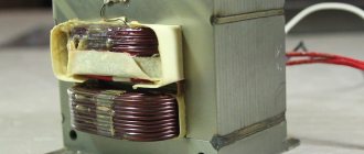
To make a step-down converter with two windings with your own hands, you need to find a round ferrite magnetic core.
These are found in old TVs and computer power supplies. In the case of a computer, the central core of the power transformer serves as the rod (it needs to be cut out). Length 2.1 cm, diameter 1.1 cm.
Most often these converters are coated with epoxy resin. In order to disassemble them, heating is required with a hair dryer. The cores are cut out with a grinder (no need to chop). The surface is usually uneven, so the posts are wrapped with tape. If the length is not enough, you can glue the two together with super glue.
Winding instructions
The core must be wrapped with tape (5 layers), a wire with the calculated diameter must be inserted into the groove, and the number of turns calculated for the primary winding must be wound along the entire length. Both ends of the winding are brought out to one side and insulated with vinyl.
The last turn must be secured (simple threads will do) to prevent unwinding.
Next, 4-5 layers of tape are wound, the structure is placed in the body of a disposable syringe 3 cm long. 2 rows of tape and the number of turns calculated for the secondary are wound on the syringe, the width of the winding is approximately 1.5 cm. Each layer must be insulated with tape or two layers of fluoroplastic tape. The ends of the second winding are brought out on both sides. As a result, three outputs are obtained from one end, and one from the other.
The finished structure is insulated with tape (5 layers), flexible wires (leads) are soldered, and another 5 layers of tape are wound.
If the wire breaks during the winding process, the ends must be stripped, twisted, soldered and insulated. The electrical strength is increased by impregnation of each layer of winding with varnish based on acrylic or epoxy resin.
In order to make a transformer with your own hands, it is not necessary to buy a new wire. The old one is also suitable if the segments are connected correctly (twisted and soldered). When winding, the turns should be pressed tightly against each other. It is not advisable to lay them perpendicular to the core (a slight tilt is required). Kinks and folds are not allowed, so a certain amount of tension is required. The insulation tape should be cut into 1.5 cm wide strips to make it easier to cover the wire.
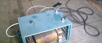
Do-it-yourself resistance welding from a welding transformer
Contact welding creates a welded connection between parts due to the following simultaneous effects on them:
- heating the area of their contact with an electric current passing through it;
- a compressive force is applied to the joint area.
There are three types of resistance welding:
- point;
- butt;
- suture
We will tell you about a homemade CT for the most popular: resistance spot welding (the other two require very complex equipment).
Spot resistance welding. East. https://moyasvarka.ru/process/kak-sdelat-kontaktnuyu-svarku-svoimi-rukami.html.
Explanations for the figure: 1 – electrodes supplying welding current to the products being welded; 2 – welded products with an overlap connection; 3 – welding transformer.
To carry out contact welding, depending on the thickness and thermal conductivity of the materials of the parts being welded, the following values of its main parameters are selected:
- electrical voltage in the power (welding circuit), V: 1…10;
- welding current value (welding pulse amplitude), A: ≥ 1000;
- heating time (passage of the welding current pulse), sec: 0.01…3.0;
In addition, the following must be provided:
- minor melting zone;
- significant compressive force applied to the welding site.
Scheme and calculation
Calculation of CT resistance welding is performed using the same algorithm as for arc welding (see above). When selecting data from a reference book (current strength and voltage of the secondary winding for spot welding of a selected grade of metal of a given thickness), it should be taken into account that the current strength of the secondary winding for such transformers is about 1000...5000 A. The secondary winding is designed, as a rule, for units of volts and It is just a few turns (sometimes one) of thick wire. Therefore, to adjust the welding current, the following diagram of the primary winding of the transformer is recommended.
Diagram of transformer windings for resistance welding. East. https://tutmet.ru/kontaktnaja-svarka-svoimi-rukami-shema-video.html.
Very often, during the operation of home-made products, it turns out that there is not enough power of the ST. In this case, it is possible to connect a second transformer in accordance with the proposed circuit.
Connection diagram of two spot welding transformers. East. https://tool-land.rusamodelnaya-tochechnaya-svarka.php.
Winding and installation
These operations are performed according to the same basic rules and in compliance with the requirements as for CT arc welding. The turns of the secondary winding should be secured with special care. To do this, you can use its leads by passing them through a heat-resistant insulator.
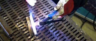
Copper rods are used as electrodes.
Electrode for spot welding in a clamp. East. https://tool-land.rusamodelnaya-tochechnaya-svarka.php.
Video
Here is an option for a spot welder from a microwave: