When carrying out welding work, especially when it comes to connecting important elements, for example, pipes operating under pressure, welders often use a special tool that allows them to control some of the characteristics of the new weld. Of course, a caliper can also be used for the same purpose, however, as practice shows, this approach is inconvenient and more labor-intensive. It is much easier and simpler to use a specialized measuring device for this, for example, a universal welder’s template or simply UShS-3.
What is a Welder Template. Its main types
Over the long history of using metal welding technology, four types of measuring devices have been created and brought to the maximum level of convenience and ease of use:
- USHK-1. Stands for “Universal Krasnovsky Template”.
- UShS-2. Often called "Cathetometer".
- UShS-3.
- UShS-4.
UShK-1
It is the simplest of the entire line. It is a drop-shaped metal plate. Two measuring scales are engraved on it and highlighted with dark wear-resistant paint.
UShK-1 allows you to measure the gap between the parts being connected, as well as three types of welding seams:
- overlap;
- T-bar;
- butt.
UShS-2
It is often called a cathetometer. As you can guess from this, it is used to determine the size of the legs of fillet welds. This is done by gradually selecting the desired angle from maximum to minimum (in this case from 14 to 4 mm ).
Externally, UShS-2 looks like three small metal parts fastened with a ring. On each of the plates there are two shaped cutouts - repeating the legs of the corresponding size (there are digital markings). The measurement is carried out by sequentially applying the plates with the cutout to the seam (perpendicularly).
The leg size is considered found when the gap between the cutout in the plate and the seam itself is minimal. Of course, it is limited - it does not cover all possible sizes of the fillet weld leg.
UShS-3
It is the most common. Can quickly control the quality and magnitude of connection defects:
- exceeding edges;
- nicks;
- bevel angles;
- gaps;
- dullness.
UShS-3 allows you to control eleven characteristics of welds and parts connected by them:
- Bevel of welded edges of parts.
- Gaps between the edges of parts.
- Size of defects.
- Convex.
- Concavity.
- Size of butt reinforcement.
- The amount of dullness.
- Seam width.
- Edge shift. By shift here we mean the difference in the level of location of the planes of the welded parts in the butt joint.
- Undercut the base of the seam. This is a discrepancy between the actual size of its leg and the planned one. It can reach up to 5 mm. This is usually caused by an excessively high operating voltage of the electric arc or an electrode that is too thick. This defect reduces the mechanical strength of the connection. It can be corrected only by carefully adding a thread stitch.
- Depth of defects. This is the distance between the defect inside the joint and its surface. The measurement range of this USS is wide enough for industrial practice. It ranges from 0 to 45º and from 0 to 50 mm. The permissible error does not exceed 0.5 mm.
UShS-4
It is the newest in origin. It partially repeats the structurally universal template of the UShS-3 welder, but has a number of improvements. For example, the Marshak-Usherov device is integrated into it. This simplifies many measuring operations.
- There is a more modern analogue of the Marshak-Usherov device - INOX or SELTOR. He is able to measure gaps before welding, the height of the weld bead, the leg of the fillet weld, and the convexity of its root. The measurement range has a limit of 20 mm .
STORAGE AND MAINTENANCE RULES
Templates must be stored in a dry and clean room, storage category 2 according to GOS 15 150−69.
When storing templates for more than 24 months from the time of their preservation, they must be preserved in accordance with GOST 9.014−78.
The conditions for transporting templates in terms of exposure to climatic factors must comply with group 8 according to GOST 15 150–69. Packed templates can be transported by all types of covered transport.
How to work with uss-3
Structurally, it consists of three parts:
- Base , with measuring scales printed on it.
- The engine is a rectangular strip of metal. It also has measuring marks and scales. It is connected to the base by a special axis.
- Pointer - has a pointed tip, attached to the slider in a certain place.
The measuring device must be protected from shock, corrosion, and chemical contamination. Before work, you need to check its integrity, the absence of bends, dents, abrasions or damage to the measuring scales.
Nine types of measurements can be carried out by the universal welder template UShS-3. Let's look at how to use it in detail for each type:
- Blurring the edges of parts. The device is applied to the edge, its length is measured using a scale at its base.
- Seam width. The UShS is located on the part - the width is determined by the scale located at its base.
- Angle of cutting edges of parts. In this case, it is placed on the surface of the part upside down. The engine is lowered until it comes into contact with the plane of the edge. The values are read from a scale around the axis of rotation of the engine. With the template in this inverted position, it is on its right side.
- The height of reinforcement of seams (both butt and corner). It is placed on the surface of the part and the slider is carefully lowered until its pointer touches the highest part of the weld. Readings are taken from the right scale.
- Displacement of the edges of parts when they are connected. To do this, place the device with its left base strictly on one of the parts. It’s more convenient to use the same one that is located to the left of the person measuring. The engine is carefully lowered down until it touches the surface of another part. Measurements are read from the scale on the far right.
- Recesses or undercuts between seam beads. It is placed with its base on the part, the slider is lowered down until its pointer comes into contact with the undercut or recess. Its value is read from the scale located on the right side of the device.
- The amount of convexity or concavity of seam undercuts. The UShS is placed on the base of the part. Then lower the slider down until its pointer touches the maximum point of convexity or concavity. The values are read from the measuring scale on the far right.
- The gap between the parts to be connected. The wedge-shaped part of the slider is placed in the space being measured, and the values are read from the corresponding scale.
- Diameter of the electrodes used. This is done by simply attaching electrodes to rectangular grooves on the upper plane of the base of the device.
- For whatever types of measurements the universal welder template UShS-3 is used (how to use it in each specific case was previously discussed in detail), it should always be positioned strictly perpendicular to the surfaces of the connected parts.
OPERATING PROCEDURE
Before starting work, it is necessary to rinse the template in gasoline in accordance with GOST 1012–72 and wipe with a clean cloth.
Measurements are carried out as follows:
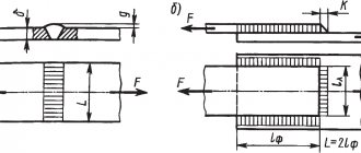
To control the depth of defects (dents, nicks), the excess of edges, the depth of the joint to the root layer and the height of the reinforcement of the seam, place the template on the forming surface of the product with plane A. Rotate the slider 2 around axis 4 until the end of the pointer 3 touches the measured surface (dent surface , seam edges, etc.). Create a report on the G scale using the K mark.
Check the bluntness and width of the seam using the E scale, using it as a measuring ruler.
To control the size of the gap between the parts being welded, insert the wedge part of the engine 2 into the controlled gap until it stops. Take a report on the I scale.
To control the bevel angles of the edges, install the UShS-3 template with plane B on the formative surface of the product, turn slider 2 until plane B of the slider aligns with the surface being measured. Take a report on the D scale of the base, using plane B of the engine as an index.
To determine the diameter of the electrodes (electrode wire), it is inserted into the grooves of the template, using the grooves as staple gauges.
Specifications
The performance of the welding welding system is guaranteed when operating in a temperature range of ±45°C.
When purchasing an instrument from specialized trade organizations and carrying out periodic checks , the accuracy of measurements is guaranteed in the following ranges:
- According to linear depth values, including undercuts and seam defects, 0...15.0±0.5 mm.
- According to angular parameters 0…450±2.50.
- Height 0…4.0±0.5 mm.
- According to the value of the seam bluntness along the welding joint line, 0...50.0±0.25 mm.
- The gaps are 1.0...4.0±0.25 mm.
- The thickness of the elements connected by welding (with grooves F, in steps) is 1.0 to 5.0 mm.
- According to the concavity value of the weld along the connecting line 0…15.0±2.50
The tool can be used for welding work using electrodes of 1-5 m. The error of the measured values is ±0.1 mm for rods with a cross-section up to 3 mm, ±0.12 mm for electrodes up to 3.25 mm in size, ±0.3 for elements larger than 3.25 mm.
Completeness
The device is supplied with:
- UShS welder template, size 3 – 1 piece;
- product passport combined with operating instructions – 1 piece;
- cover – 1 pc.
When in use, the template must not be subjected to impacts or dropped to avoid mechanical damage . Moving the tool with measuring planes along the surfaces to be controlled is not allowed.
The interval between calibrations of the template is established by the metrological service of the consumer enterprise, depending on the conditions and intensity of use of the tool, the volume of products to be determined for quality. The frequency of verification recommended by the manufacturer is 12 months.
Usherov-Marshak pattern
You can see how it is used in the picture. The cutting size is 60 o. Accordingly, each side is 30 o.
In addition to the angle, you can measure the bluntness of the edges, the height of the reinforcement, the amount of convexity - “convexity” (not to be confused with the leg).
The width of the seam can be determined approximately. You can also measure the depth of defects: inter-roller depression, undercut, lack of fusion of edges.
Add a comment Cancel reply
You must be logged in to post a comment.
Is it worth BUYING, reviews from welders:
- Welding transformer PATRIOT 200AC 102.00 RUR
- Charger GreenWorks G24C RUB 2,490.00
- Voltage stabilizer PRORAB DVR 1000 2597.22 RUR
- Stabilizer Resanta ASN-2000 N/1-C Lux 3610.00 ₽
- Voltage stabilizer Stavr SN-2000 3920.00 RUR
- Welding machine BauMaster AW-79161 3990.00 RUR
- Hitachi AB17 charger RUB 4,076.87
Source: svarka-master.ru
Description
The universal welder's template is produced in accordance with the descriptions of GOST 15150 from high-quality tool steel . An anti-corrosion coating is additionally applied to the elements of the device. The manufacturer ensures that the functionality of the device is maintained without reducing accuracy for at least 10 thousand measurement cycles.
The tool consists of the following elements:
- Main measuring panel.
- A slider with variable thickness throughout the element.
- Pointer arrow.
- Slider rotation axis
The following planes and measurement areas are highlighted on the central part of the device:
- A - installation plane, used for laying on straight surfaces of the connected product to determine the characteristics of the seam.
- B – plane for measuring the angle bevel for welding.
- B – moving pointer.
- G – scale for measuring seam dimensions in height.
- D – ruler for setting the angle of the beveled edge.
- E – ruler that determines the bluntness and total height of the seam.
- I is a linear scale used to establish the distance between the products to be welded.
- F – recesses to reveal the thickness of the metal in the welding area.
- K – index line on the slider, used to read the measurement result along the G ruler.