SHARE ON SOCIAL NETWORKS
FacebookTwitterOkGoogle+PinterestVk
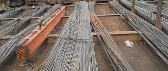
The production of reinforced steel, like the production of goods from other industries, is unified. To determine the quality of products, requirements for products according to various parameters, specially developed by Gosstandart, are used. In this type of production, standards are established for the diameter, weight and cross-section of rods. All these characteristics are united by one term – reinforcement range. This article will tell you in more detail about the set of requirements.
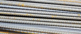
The reinforcement has established standards for cross-section, weight and diameter
Characteristics of fittings
We strive to do everything possible to simplify the selection of products, offering our customers tables reflecting the main properties of fittings.
First of all, you should pay attention to the values that affect the quality of adhesion of products to concrete, presented below:
| Nominal diameter, mm | Cross-sectional area, cm2 | Weight1 m | |
| theoretical, kg | permissible deviation, percent. | ||
| 6 | 0,283 | 0,222 | +10 |
| 7 | 0,385 | 0,302 | -9 |
| 8 | 0,503 | 0,395 | |
| 10 | 0,785 | 0,617 | +5,5 |
| 12 | 1,131 | 0,888 | -7 |
| 14 | 1,54 | 1,21 | +4 |
| 16 | 2,01 | 1,58 | -6 |
| 18 | 2,64 | 2 | +3,5 |
| 20 | 3,14 | 2,47 | -5,5 |
| 22 | 3,80 | 2,98 | +3 |
| 25 | 4,91 | 3,85 | -5 |
| 28 | 6,16 | 4,83 | +3 |
| 32 | 8,04 | 6,31 | -5 |
| 36 | 10,18 | 7,99 | |
| 40 | 12,58 | 9,87 | |
| 45 | 15,90 | 12,48 | |
| 50 | 19,63 | 15,41 | +2 |
| 55 | 23,76 | 18,65 | -4 |
| 60 | 28,27 | 22,19 | |
| 70 | 38,48 | 30,21 | |
| 80 | 50,27 | 39,46 | |
Reinforcement range: additional marking options
To determine more specific characteristics of the reinforcement, a special additional marking system has been created. For example, the abbreviation A5K means that these are class A5 profiles, and the letter K indicates the presence of additional corrosion protection. To do this, the material is treated with special agents that ensure its durability.
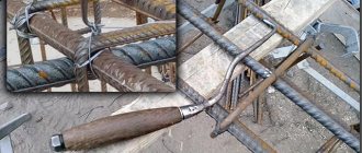
The presence of the letter C in the marking indicates that the reinforcement can be welded. It must be taken into account that not all products belonging to different classes can be welded together, especially in the absence of the C mark in the designation.
If the marking contains the letter K, this means that the reinforcement has additional corrosion protection
Speaking about the range of fittings, we should mention such a term as shut-off (or pipeline) valves. These types of profiles are used in plumbing work. Accordingly, as a separate subtype of material, this reinforcement has its own classes and markings. In this case, the main parameter of choice is tightness. This criterion indicates the quality of the assembly in the pipeline, without which it is impossible to assemble it. The tightness indicator is indicated in the characteristics on the packaging of the material.
Helpful advice! It is better to connect reinforcing bars with different markings and in the absence of the letter C in the designation, using special couplings and wire.
Reinforcing wire
| Nominal diameter, mm | Design cross-sectional area, mm2 | Theoretical mass I m, kg, classes | Nominal diameter, mm | Design cross-sectional area, mm2 | Theoretical mass I m, kg, classes B - II, Bp-II | |
| B-I, B-II, Bp-II | Bp-I | |||||
| 3 | 7,06 | 0,056 | 0,052 | 6 | 28,3 | 0,222 |
| 4 | 12,56 | 0,099 | 0,092 | 7 | 38,5 | 0,302 |
| 5 | 19,63 | 0,154 | 0,144 | 8 | 50,3 | 0,395 |
Functionality
For reinforcement of precast concrete, reinforcement up to class A600 is used. Classes above this are built into prestressed reinforced concrete structures.
Types of fittings by purpose.
- Working (longitudinal and transverse): accepts the main types of loads in a reinforced concrete product, the diameter is determined by calculations.
- Assembly (distribution and structural): for the formation of three-dimensional frames and meshes.
- Distribution: ensures the correct location of the working rods.
- Structural: not calculated; installed in places that may be subject to random loads.
- Anchor: for the formation of embedded elements, including gripping loops.
The consumption of reinforcement of all types in reinforced concrete structures ranges from 50 to 80 kg per cubic meter of concrete, but not less than 8 kg. The calculation of the required quantity for a strip foundation is given below.
Reinforcing ropes
| Class | Diameter, mm | Design cross-sectional area, cm2 | Estimated weight 1 m, kg at laying step | ||
| conditional | Nominal, D | ||||
| 10D | 16D | ||||
| K-7 | 4,5 | 4,65 | 0,127 | 0,102 | 0,100 |
| 6 | 6,20 | 0,227 | 0,181 | 0,173 | |
| 7,5 | 7,75 | 0,354 | 0,283 | 0,279 | |
| 9 | 9,30 | 0,510 | 0,407 | 0,402 | |
| 12 | 12,40 | 0,906 | 0,724 | 0,714 | |
| 15 | 12,50 | 1,416 | 1,132 | 1,116 | |
| Class | Nominal diameter, mm | Design cross-sectional area, cm2 | Theoretical mass1 m, kg |
| K-19 | 14 | 1,287 | 1,020 |
| K-2*7 | 18 | 1,019 | 1,801 |
| K-2*7 | 25 | 1,812 | 1,428 |
| K3*7 | 10 | 0,381 | 0,299 |
| K3*7 | 13 | 0,678 | 0,583 |
| KZ*7 | 16,5 | 1,062 | 0,825 |
| K3*7 | 20 | 1,527 | 1,209 |
| KZ* 19 | 16,5 | 1,031 | 0,795 |
| KZ* 19 | 22 | 1,809 | 1,419 |
It is necessary to have an understanding of the documents defining the characteristics of the fittings:
| Type of fittings and documents regulating quality | Class | Diameters of fittings, mm | |||||||||||||||||||||
| 3 | 4 | 4,5 | 5 | 6 | 7 | 7,5 | 8 | 9 | 10 | 12 | 14 | 15 | 16 | 18 | 20 | 22 | 25 | 28 | 32 | 36 | 40 | ||
| Hot rolled smooth rod, GOST 5781-75 | A.I. | + | + | + | + | + | + | + | + | ||||||||||||||
| Hot-rolled rod of periodic profile, GOST 5781-75 | A-II | + | + | + | + | + | + | + | + | + | + | — | — | ||||||||||
| A-III, At-Sh | + | — | + | + | + | + | + | + | + | + | + | + | + | + | + | ||||||||
| A-IIIb | — | — | — | — | — | — | — | — | — | — | — | — | — | — | — | ||||||||
| GOST 5.1459-72 * | A-IV, ?t-IVc | + | + | + | + | + | 0 | 0 | 0 | 0 | 0 | ||||||||||||
| Thermally strengthened rod of periodic profile GOST 10884-81 | A-IV | — | — | — | — | — | — | — | — | — | — | ||||||||||||
| AV, ?t-V | + | + | + | + | + | + | 0 | 0 | 0 | ||||||||||||||
| AV, ?t-VI | + | + | + | + | + | 0 | 0 | 0 | 0 | 0 | |||||||||||||
| Ordinary smooth reinforcing wire, GOST 6727-80 | B.I. | — | — | — | |||||||||||||||||||
| The same, periodic profile GOST 6727-80 | Bp-I | + | + | + | |||||||||||||||||||
| High-strength reinforcing wire, smooth, GOST 7348-81 | B-II | — | + | + | + | 0 | 0 | ||||||||||||||||
| The same, periodic profile GOST 7348-81 | Bp-II | 0 | 0 | 0 | |||||||||||||||||||
| Reinforcing ropes GOST13840-68 * | K-7 | + | + | + | + | ||||||||||||||||||
| Reinforcing ropes GOST 13840-68* | K-19 | 0 | |||||||||||||||||||||
Legend: + diameters and classes of effective reinforcing steel recommended for use, — — diameters and classes of reinforcing steel excluded from the range; 0 - assortment.
Notes: 1. The diameters of the reinforcement are taken in accordance with the assortment according to the relevant GOST or TU, taking into account the instructions for the scope of various classes of steel; diameters and classes of reinforcing steel excluded from the assortment; 0 - steel assortment - according to paragraphs. 2.18—2—25 SNiP P-21-75. 2. Steel of class A-IIIb with diameters of more than 20 mm, reinforcement strengthened by drawing at construction industry enterprises, is allowed for use as prestressed reinforcement in the absence of reinforcing steel of higher classes. 3. When manufacturing structures, it is allowed to replace class Bp-I wire with available class B-1 wire.
It is important to know the actual weight of reinforcement of a certain diameter:
Scope of application, features of fittings: diameter, classes, markings, compliance with GOST
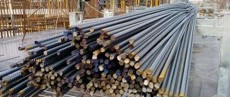
Reinforcement is an important component in the general list of building materials. It is characterized by a wide range of applications at various stages of building construction. Not a single reinforced concrete structure can do without it, serving as reinforcement and support both in the foundation of a small house and in the construction of a large-scale railway bridge or overpass. Reinforcement technology is even used to strengthen glass structures.
Reinforcement is used in construction at various stages of construction
Even at the initial stage of developing design estimates, every self-respecting engineer and architect has at hand a special table of the ratios of weight and footage of reinforcement, as well as cross-sections of reinforcing bars in accordance with established state standards. The main one among them is GOST 5781-82. Also, products must comply with GOST 52544-2006, STO ASChM 7-93, TU 14-1-5254-94. The standards regulate the requirements for a specific type of reinforced products. Their totality corresponds to the term – reinforcement assortment.
The fittings are round metal rods with a smooth or corrugated surface. They are made from several types of steel. The diameter of the rods ranges from 4 to 80 mm. The product range is divided into classes A1 – A6.
Diameter, that is, the cross-sectional size of a reinforcement bar or wire, is the main indicator underlying the product range. Hence the corresponding terms: reinforcement 8 mm or weight 1 m of reinforcement 12. These products are classified according to other properties, including strength, wear resistance, specific gravity and other characteristics, which we will consider further.
Reinforcement classes: product range by strength and mechanical parameters
The word assortment (or assortment) in French sounds like assortir and means “to select,” that is, to sort into varieties in accordance with typical characteristics. These parameters include:
Reinforcement differs in various parameters, such as dimensions, profile and material for manufacture
- material used to manufacture products;
- reinforcement dimensions, such as size, diameter, surface type;
- profile.
Helpful advice! Products are packaged according to their diameter classification. Reinforcing metal products up to 10 mm are sold in coils, and above this parameter they are packaged in rods of a certain length.
Reinforcement is used in construction work in the form of rods, mesh, wire or frame. Based on its purpose, it is divided into structural, anchor, installation or working. This takes into account the presence or absence of tension, as well as the need to strengthen the structure in a certain area. Reinforcement can be longitudinal or transverse.
Reinforcement is also marked and classified according to other characteristic features, but first of all, the diameter of the reinforcement is taken into account, as well as the degree of strength, flexibility and mechanical characteristics. The symbol in the assortment marking is the capital letters A (less often B) with a certain index, which indicates that the reinforcement corresponds to a particular class. We will consider the main and most popular classes of reinforcement in construction in this article.
The fittings are divided into several classes, each of which has its own characteristics
Rebar weight table
| Profile number (nominal diameter) | Weight, kg/m |
| 6 | 0,222 |
| 8 | 0,395 |
| 10 | 0,617 |
| 12 | 0,888 |
| 14 | 1,210 |
| 16 | 1,580 |
| 18 | 2,000 |
| 20 | 2,470 |
| 22 | 2,980 |
| 25 | 3,850 |
| 28 | 4,830 |
| 32 | 6,310 |
| 36 | 7,990 |
| 40 | 9,870 |
| 45 | 12,480 |
| 50 | 15,410 |
Familiarization with the proposed valve tables will allow you to purchase products that are ideal for solving specific practical problems at minimal financial costs.
How much does a meter of reinforcement weigh and how many meters of reinforcement per ton: examples of calculations
Skills in calculating the diameter of the rods will also be needed when calculating the weight of the reinforcement. Such knowledge is necessary when drawing up projects and construction estimates. Accurately determining the weight of the reinforcement will help you save on the purchase of materials. It is important to note the fact that large manufacturers sell reinforcement at a price of 1 ton, and not per meter. However, the cost of production in this case will be several times cheaper.
As an example, we can consider how to calculate the mass of the necessary material for the construction of a reinforced concrete foundation with a total length of 100 m. The diameter of the reinforcement is 10 mm. We look for the necessary data in the table, they correspond to 617 g. We multiply this number by 100 and get 61 kg 700 g. The weight of 1 meter of reinforcement can be calculated in other ways (there are three in total):
- according to the normative table;
- using data on the specific gravity of reinforcement;
- using the reinforcement weight calculator.
Thanks to accurate calculations of the required weight of the reinforcement, you can save on the purchase of material
The required number of rods by standard weight is calculated using the above weight table in relation to the linear meter. This is the simplest calculation option (except for an online calculator).
For example, for construction it is expected to use 2300 m of reinforcement 14. The weight of 1 meter of rods is 1.21 kg. We make calculations: 2300 * 1.21 = 2783 kg. Thus, to complete this volume of work, 2 tons of 783 kg of steel rods will be required. The number of rods in one ton of the corresponding diameter is calculated in the same way. The data is taken from the table.
Selection of reinforcement for section 1-1
In this section, our slab can be considered as a single-span beam with consoles. Let us again determine the value of the moments on the supports (under the walls) and in the span. When determining the moments, we accept the length of the consoles k1 = 1.4 m and the span l1 = 7.8 m. With q1c = 520.91 kg/m, the change in the support reaction A will be 520.91 0.2 = 104.2 kg, then A1 = 2865 - 104.2 = 2758 kg
MA1 = Ms1 = q1сk12/2 = 520.91 1.42/2 = 375 kgf m or 37500 kgf cm
Мx1 = q1сx12/2 - A1(x1 - k1) = 520.91 5.32/2 - 2758(5.3 - 1.4) = -3440 kgf m or -344000 kgf cm
where x1 = A1/q1с = 2758/520.91 = 5.3 m (taking into account the fact that we do not take into account the width of the supports, the x value coincides with the middle of the slab, as it should be).
With ho1 = 18 cm
A0p = Mx/bh201Rb = 344000/(100 182 117) = 0.091
then at ηп1 = 0.952
Fap1 = Mх1/ηh01Rs = 344000/(0.952·18·3600) = 5.57 cm2.
This requirement is satisfied by 5 rods with a diameter of 12 mm and a cross-sectional area of 5.65 cm2.
According to the moment equation:
M01 = A1x1 - q1с(k1 + x1)2/2 = 2758x1 - 520.91(1.4 + x1)2/2 = 0
Then
x1(1) = 0.26 m, x1(2) = 7.54 m.
With these parameters, it is easier to place all the rods beyond the edge of the supports. And for the same reasons of unification, we accept the reinforcement of the consoles as in section 2-2.
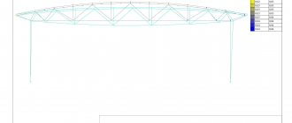
Conclusion : to reinforce the slab you will need reinforcement of 3 different diameters. For the purpose of unification and increased reliability, it is possible to accept reinforcement of 2 diameters 18 mm and 12 mm. As a result, the slab reinforcement scheme when using reinforcement of 3 diameters will look something like this:
Figure 397.1
The structural reinforcement necessary to support the working reinforcement of the upper layer is not shown in the diagrams. Meanwhile, in our slab, most of the reinforcement is located on top, and not, like in a floor slab, on the bottom. Therefore, in order to maintain the working reinforcement of the upper layer in the design position when walking and when pouring concrete mixture and when vibrating the concrete mixture, it is advisable to lay rods with a diameter of 8-12 mm (this can also be smooth reinforcement) with a pitch of no more than 500 mm, then it becomes possible to weld the transverse reinforcement to support the reinforcement of the top layer. The distance between the transverse reinforcement bars should also generally not exceed 500 mm. In our case, to simplify installation, we can lay half of the cantilever rods along the entire length of the slab, then the mesh of structural reinforcement will be 400x400 mm, and weld transverse reinforcement at the nodes of the structural mesh. In addition, for the overall stability of the reinforcement frame, it is advisable to weld several inclined rods.
After this, a specification of the reinforcement necessary to reinforce the foundation slab is drawn up. Such a specification looks something like this (taking into account structural reinforcement):
Pos.
| Designation | Name | Col. | Unit/total weight, kg | Notes |
| 1 | Ø12А400 l = 3000 | 56 | 2.66/149 | |
| 1′ | Ø10А400 l = 6600 | 56 | 4.07/228 | design and calculation |
| 2 | Ø18А400 l = 3500 | 56 | 7/392 | |
| 3 | Ø10А400 l = 5500 | 112 | 3.39/380.1 | |
| 4 | Ø10А400 l = 2500 | 82 | 1.54/126.5 | |
| 4′ | Ø10А400 l = 6700 | 82 | 4.1/339 | design and calculation |
| 5 | is recruited from the design and calculation | |||
| 6 | Ø10А400 l = 3500 | 74 | 2.16/159.8 | |
| 7 | Ø12A400 l = 8400 | 45 | 7.46/335.7 | |
| 8 | Ø12A400 l = 200 | 2360 | 0.1776/419.1 | transverse structural |
| concrete class B20 | 43.5 m3 |
Thus, to reinforce the slab foundation, approximately 2529.2 kg of reinforcement will be required, of which about 700 kg for purely structural reinforcement, and 43.5 m3 of concrete. With the cost of 1 ton of reinforcement about $700-800 and a cubic meter of concrete about $50, the foundation slab will cost about $4,000 (and this does not include the cost of work).
And here the question arises: since the house is relatively small and relatively light, and the spans between the walls are not small, does it make sense to use a strip foundation for the house? The question is good, but the answer to it is given separately.
And one more small, but very important detail: it is advisable to concrete the slab immediately, and this is more than 40 m3 of concrete. In this regard, it is more advisable to first carry out concrete preparation from concrete class B5 - B7.5 (if possible) with a thickness of at least 100 mm (in any case, this is recommended by the “Guidelines for the design of slab foundations of frame buildings ...”), and possible unevenness this will smooth out the base and simplify the installation of reinforcement. In addition, after concrete preparation, you can perform high-quality waterproofing, if there is such a need. Then the minimum thickness of the protective layer for the lower reinforcement should be at least 35 mm and, accordingly, the height of the slab can be reduced by another 35 mm and the consumption of concrete higher class by 6.6 m3, but then you will have to recalculate the cross-section of the reinforcement of the upper layer.
Other questions may arise here: for example, how to calculate a slab if the house plan is not symmetrical? In this case, to simplify the calculations, you can still consider the slab as symmetrical with the difference that the length of the spans will be equal to the larger value available, which will lead to an increased safety margin, and therefore an increase in the cost of the house. Or order a calculation from a specialist, which will also lead to additional waste of funds.
Delivery status
An area where the private developer almost always faces unpleasant discoveries.
The reinforcement is supplied in coils (up to 22 mm thick) and rods. The skein should consist of one, maximum two segments.
Length of rods: 6 - 18 m. Rods according to standard 34028-16 come in measured length (MD), measured with unmeasured (MD1), unmeasured (ND, 6 - 12 m). In the supply of MD1, no more than 3% of unmeasured rods with a length of at least 2 m are allowed.
Rods of irregular length are cheaper. But the probability of deception here is quite high. If it is not possible to count and measure each rod, you will pay more. Please also take into account that due to the overlap of individual rods, the consumption of reinforcement will increase.
The skeins should unwind freely, and the overlap of the turns should not interfere with unwinding.
Corrosion
The surface of a concrete structure must be looked after and any cracks that appear must be eliminated in a timely manner.
Due to the ability of iron to react with oxygen, steel products are inherently sensitive to the atmosphere. The interaction between it and oxygen in the air causes an oxidation process, more often called rust or corrosion.
Surface rust of the reinforcement that is located inside the structure does not affect its properties. The alkaline environment prevents this. It can even increase the bond between the bar and the concrete. However, a long process of surface oxidation (with access to air) can eventually lead to internal corrosion, which will inevitably weaken the steel bar.
The resistance of reinforcement to corrosion is determined by the chemical composition of the steel, the production method, and is designated by the letter K. In this case, the reinforcement is made of stainless steel. In private construction, it is irrational to use such rods.
It's not just about cost. Damage to the surface by metal slings or friction against the steel of the body creates pockets of corrosion.
Ferrous reinforcing metal is protected by hot-dip galvanizing or coating with epoxy resins.
Selection of reinforcement for section 2-2
Let us again determine the value of the moments on the supports (under the walls) and in the span. When determining the moments, we will take the length of the consoles k2 = 1.4 m and the span l2 = 3.8 m. And we will reduce the value of the support reaction A2 by 825.5 0.2 = 165.1 kg. Then the support reaction A will be A2 = 2865 - 165.1 ≈ 2700 kg. At q2c = 825.5 kg/m
MA2 = Ms2 = q2сk22/2 = 825.5 1.42/2 = 809 kgf m or 80900 kgf cm
МВ2 = q2с(k2 + l2)2/2 - A2l2 = 825.5(1.4 + 3.8)2/2 - 2700 3.8 = 900.8 kgf m or 90080 kgf cm
Mx2 = qx22/2 - A(x2 - k2) = 825.5 3.272/2 - 2700(3.27 - 1.4) = -600.4 kgf m or -60040 kgf cm
where x2 = A2/q2с = 2700/825.5 = 3.27 m.
The values of the moments in this section are significantly less than in section 3-3 and this is logical, since the load, and most importantly, the spans in this section are much smaller. And the difference in the values of the moments is insignificant, so it is enough to select the reinforcement section according to the maximum moment, but it should be remembered that the relative height of the section will change, since we already have reinforcement in section 3-3. At h'o2 = 13 cm
А0В2 = МВ2/bh'202Rb = 90080/(100·132·117) = 0.045
This value is quite close to the obtained A0p3, therefore, without further scrupulous calculations, we will accept the reinforcement of 1 linear meter of slab width in a given section with 5 rods with a diameter of 10 mm.
According to the moment equation:
М02 = A2x2 - q2с(k2 + x2)2/2 = 2700x2 - 825.5(1.4 + x2)2/2 = 0
Then
x2(1) = 0.63 m, x2(2) = 3.11 m.
Thus, the length of the rods for reinforcing the consoles will be k2 + b + 0.59 + 0.23 = 1.4 + 0.2 + 0.63 + 0.23 = 2.46 m (rounded to 2.5 m). Length of bars for reinforcement under the middle support B2: 2(l2 - x2(2)) + b + 0.46 = 2(3.8 - 3.11) + 0.2 + 0.46 = 2.04 m (taking into account the fact that we adopted a slightly oversized reinforcement section and taking into account some pinching of the reinforcement in the stretched layer of concrete, we can round the length of the rods to 2 m). Minimum length of rods for span reinforcement: 0.2 + 3.11 + 0.23 = 3.54 m (rounded to 3.5 m) for herringbone reinforcement.
Basics of calculating strip foundations
The most common type of foundation in individual construction is monolithic strip. It is easy to construct, quite durable and has the necessary rigidity. It is arranged in the form of a shallow or recessed structure.
The depth of placement, effective loads and the width of the working section of the base are important for calculating the reinforcement for the foundation.
Strip foundation Source eurohouse.ua
Determination of depth
The mark of the base of the base is selected depending on the type of soil:
- in clayey, silty and fine sandy soils, the foundation is supported on a non-freezing layer below the groundwater level;
- for non-heaving and slightly heaving soils, the level of the base should not be lower than 0.5 m from the top of the existing ground level;
- if there is a basement, the strip base is buried 0.5 m below the floor, the columnar base - 1.5 m.
The type of soil, the position of the groundwater level and the presence of weak lenses - quicksand - are determined by drilling or digging holes. The depth of soil freezing in each region is indicated in SNiP “Building Climatology”.
Load collection
At this stage of the calculation, all possible loads acting on the foundation are summed up:
- own weight;
- the mass of walls, floor slabs, roofs, roofing, floors and finishing;
- impact from people, plumbing equipment, furniture, partitions located inside the building;
- standard snow load.
All information is contained in the tables of SNiP 2.01.07-85* “Loads and impacts”.
The total value is divided into linear meters in strip foundations, and by the number of supports - in pile or columnar ones.
Outsole width
Reinforcement of a strip foundation Source guru-remonta.ru
The width of the sole is a value that helps to calculate the reinforcement for a strip foundation. For massive brick walls, T-shaped strips are used, the overhangs of which, due to the larger support area, reduce the pressure on the soil. Lighter frame and foam concrete structures are erected on bases with a rectangular cross-section.
When calculating the size of the sole, the maximum pressure on the ground and the load from the structure on the load-bearing sections of the foundation beams are taken into account. In low-rise construction, as a rule, structures with a width of 20-40 cm are used.
See also: Catalog of companies that specialize in foundation repair and design.
The principle of selecting reinforcement according to its diameter
The thickness (diameter) of reinforcement for the foundation is selected based on the required relative content of working reinforcement. The cross-sectional area of the reinforcing longitudinal elements at the cut must be at least 0.1% - this value is specified in the regulatory document SNiP 52-01-2003 “Concrete and reinforced concrete structures”. What does it mean?
Just that the area of the reinforcement in relation to the total area of the foundation in the section (to the cross-sectional area) should be in a ratio of 0.001 to 1.
In the article “Calculation of reinforcement for a foundation,” we provided a fairly detailed analysis of the methodology for selecting reinforcing elements - their quantity and diameter - based on the selected parameters of the house foundation. The calculations use the table below.
Calculation for a pile foundation
Pile foundations are supports (all-metal or bored) immersed in the ground, transmitting the load from the building and connected at the top by a steel, reinforced concrete or wooden grillage.
Pile foundation Source stroyfora.ru
Bored foundations are used in private construction:
- when constructing frame or wooden buildings with low mass;
- on weak soils, where other foundations cannot be made - peat bogs, swamps, highly heaving wet soils;
- in difficult terrain - on hilly, gully terrain.
A disadvantage that leads to higher construction costs is the cold base and the impossibility of installing a floor on the ground. The advantage is the absence of excavation work. The piles are screwed in with a special drilling rig or holes are drilled in the ground, followed by the installation of formwork, reinforcement and concreting. For non-flowing soils, the solution is poured directly into the well.
Reinforcement of a pile foundation Source housepic.ru
Scheme for calculating reinforcement for a bored pile foundation.
- Determine the type of soil using GOST “Soils. Classification".
- Calculate permanent and temporary loads (SNiP “Loads and Impacts”).
- From VSN 5-71, the bearing capacity of the soil is selected depending on its structure.
- According to available information, the load R per linear meter of the grillage is found by dividing the total mass by the perimeter of the building.
- The load-bearing capacity of the pile is determined by the formula P = (0.7x R x S)+(U x0.8 x fin x li), where
- R is the bearing capacity of the soil,
- S is the area of the final section of the support,
- U is the perimeter of the pile section,
- fin - soil resistance, determined according to table VSN 5-71,
- li is the height of the soil layer that provides resistance to the side surface of the pile.
The distance between the supports is determined by the formula I = P/Q, where P is the load-bearing capacity of the pile (item 5), R is the linear load on the grillage (item 4). The number of piles is determined based on the calculated distance between the supports and the size of the building. The structures are reinforced with a vertical frame of at least 4 rods with a diameter of 10 to 16 mm with horizontal piping made of smooth reinforcement Ø 6-8 mm. Issues 25-30 cm long are left along the top.
The grillage is designed as a structure similar to a strip foundation.
Online pile foundation calculator
To find out the approximate cost of a “grillage on piles” foundation, use the following calculator: