Vertical turning lathe 1512 technical specifications, passport On sale you can find a relatively small number of machines that can be used for processing large-sized parts. Among all the models created at the time of the existence of the USSR, we note the 1512 rotary lathe. Its purpose is to process parts of medium and large sizes. Due to its high reliability and practicality in use, this model became the basis for the creation of various modifications and was actively imported to various countries around the world.
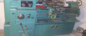
Vertical lathe 1512
The technical characteristics of the 1512 rotary lathe determine its applicability in mechanical engineering, shipbuilding or other production. When installing additional equipment, the purpose of the 1512 vertical turning lathe is significantly expanded; it can be used to carry out more than 10 types of processing of workpieces made of various alloys.
Specifications
Considering the technical characteristics, we will also pay attention to deciphering the name of the machine 1512, which was given in accordance with previously introduced standards: the first digit indicates membership in the turning group, the second in the rotary-turning subgroup, the next two - the maximum size of the workpieces installed. The main technical characteristics are as follows:
- The maximum height of the cutting tool above the table is 1,000 mm.
- The workpiece weight limit is 5,000 kg.
- The installed faceplate can rotate at a frequency from 1 to 250 rpm. At the same time, the manufacturer included in the passport information about the presence of two rotation speed shift gears. The adjustment is stepless.
- The electrical circuit provides for the installation of a main electric motor, which has an impressive power of 55 kW. This information determines that the 1512 rotary lathe is placing a significant load on the facility's power supply.
- The traverse can move in the vertical direction over a distance of 660 mm. Movement is limited by mechanical stops.
- The machine layout also determines the presence of a support, which can move horizontally by 775 mm and vertically by 700 mm.
- When choosing a cutting mode, you should pay attention to the fact that the maximum permissible force at the time of processing is 35 kN.
- There is a mechanism for rotating the slider at an angle of no more than 45 degrees.
- The installed turret has 5 positions. It is mounted on a cylindrical bushing. The master changes the cutting tool by pressing the corresponding key on the control panel. Rotation is transmitted from an electric motor through gears.
- The main support can move vertically by 1,000 mm, horizontally by 630 mm, the maximum cutting force is 25 kN. The position of this element can be set at a speed of 2,000 mm/min. The passport also contains information that this caliper has 18 feeds.
Download the passport (operating instructions) of the rotary lathe 1512
When choosing this model, it is worth considering that its weight is 14,800 kg. This point determines the presentation of special requirements for the base on which the equipment will be installed. The electrical circuit of the equipment determines its connection to a three-phase network with a voltage of 380V.
Design features
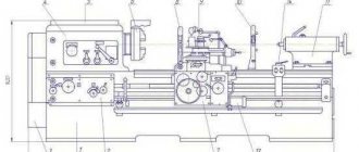
Conducting a review of the 1512 rotary lathe, we note that the layout of all components allows you to correctly position the cutting tool for large overall dimensions of the parts. The rotary machine 1512, the passport of which was included in the delivery set, consists of the following components:
- The table on which the workpiece is fastened. It is usually round in shape.
- Caliper and faceplate.
- The control unit is a pendant control panel. At the same time, it has a special suspension, which eliminates the possibility of the remote control getting into the cutting zone.
- The bed is quite large and made of cast iron. The bed is designed to dampen vibration and other loads.
- The 1512 rotary lathe has a crossbar, as well as a mechanism for moving along it.
- The model also has a horizontal caliper with a feed box.
Components of the machine 1512
In order for the device to have a long service life, lubricant is supplied to the rubbing elements. A special pump was installed for this purpose.
Installed gearbox
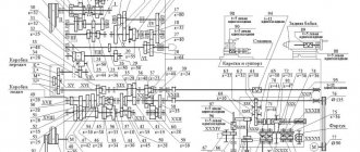
The machine device provides for transmission of rotation to the faceplate through a gearbox. The features of this structural element are the following elements:
- The kinematic scheme provides for the transmission of rotation through a V-belt drive. It is silent, but causes a slight loss of efficiency.
- The installed gearbox has 18 speed levels.
- The operating instructions determine the possibility of setting the required number of revolutions through the pendant.
- The electrical circuit of the 1512 machine is connected to an electromagnetic type clutch, the main purpose of which is to support stepwise constant speed at the moment of passing the ends, as well as continuously variable gear shifting.
- When the number of rotations per minute is high, gear shifting is carried out in steps. Depending on the speed, switching can be carried out in 2-4 stages. For this purpose, the design has six shafts, which are mounted on rolling bearings.
- The previously described clutch switches automatically. From 1st to 12th gear, rotation is adjusted without steps.
It is worth considering the fact that the device does not have a braking mechanism. The faceplate is stopped by simultaneous activation of all three electromagnetic clutches.
Kinematic diagram of machine 1512
Table Features
The table is an important element of the machine. As previously noted, the 1512 rotary lathe can process workpieces weighing up to 5,000 kilograms. The following are the design features:
- The table is round and has a rather complex structure, part of which is represented by a cast iron body.
- The guides also have a round shape, which allows you to fasten cylindrical workpieces.
- The body is made of cast iron by casting. It has a large number of ribs, which significantly increase the rigidity of the structure and distribute vibration.
- The upper part of the housing has annular projections that fit into the annular grooves of the faceplate. Due to the created labyrinth, chips and emulsion, as well as other contaminants, do not get inside the table.
- The required force is transmitted to the faceplate through gears having a conical shape.
The design features of the table determine the possibility of basing large and heavy workpieces.
Machine feed box
Feed box of machine 1512
Considering the main parameters of the feedbox, we note the following points:
- It is located on the right at the end of the cross member. The side caliper with the feed box is mounted directly on the body.
- All structural elements are hidden in a body made of cast iron. The casting has a box-shaped shape and additional stiffening ribs, which determines the high rigidity of the structure.
- Torque is transmitted from a vertically located splined shaft, which is connected to the operation of the gearbox.
The gears installed during operation of the rotary lathe do not disengage when changing gears.
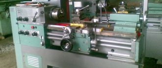
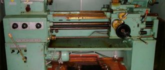
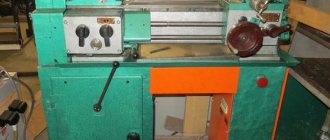
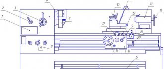
Appearance of machine 1512
Cross member
The design of the 1512 rotary lathe has a crossbar, which is located on the vertical guides of the bed. The features of this node are the following:
- Considering the description of the 1512 rotary lathe, we note that the crossbar is represented by a casting.
- The design has rectangular guides located in the horizontal direction. They were created to allow the movement of the upper support.
This element ensures that the head is brought to the desired point when turning and performing other operations.
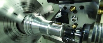
Work carried out
The scope of application of the model 1512 is very extensive. As a rule, it is installed in the case of medium-scale and piece production of various parts. This is due to the fact that in the case of turning large workpieces, a large layer of material is removed. Even when using a cutting tool made of wear-resistant material, a layer can be removed in one pass, provided that the maximum force should not exceed 35 kN.
Basic operations that can be performed on this equipment:
- Machining of conical and cylindrical surfaces.
- Performing boring operations.
- Passing a cutting tool along a flat surface, which is an end.
- Carrying out work on creating holes and boring them.
The model has been produced since 1935 by the Krasnodar Sedina plant. After using this model for a long time, a fairly large number of different modifications appeared, which also became popular.
Connection diagram
Specifications
Full technical specifications are described in the instruction manual.
- The installed workpiece can have a maximum of the following parameters in terms of weight, height and diameter: 4000 kilograms, 1000 and 1250 millimeters, respectively.
- 11200 is the diameter of the platform itself.
- 5-250 rpm – angular speed for the faceplate.
- The tool feed rate is 0.03-12.5 revolutions per minute. In total, this and the previous indicators have up to 18 steps.
- 5-1800 – speed according to installation movements.
- The power of the main movement is 30 kW.
- 16.5 is the total mass for installation.
How do rotary lathes work?
The structure rests on a hollow post cast from cast iron in a vertical position. All other components connect to this part.
Main node devices
There are not many components in the desktop:
- Faceplate.
- The previous part is installed complete with the spindle.
- A mandatory addition is supports in a cast iron housing with bearings.
- Drive device.
The design is equipped with cylinder-shaped, roller-type bearings. They are mounted to center the platform and control radial forces during cutting. The radial clearance parameters in the supports are individually selected. To do this, using adjusting nuts, tighten the inner rings, which have a conical surface.
Frictional forces and the weight of the workpieces create an additional load that is transmitted to the ring guide responsible for sliding. This part has central lubrication. A cylindrical helical gear imparts rotational force to the faceplate. The force itself is directed from the drive shaft. The latter is tied to the main drive responsible for movement.
Speed control box
Popularly, such a knot is also called the “carousel pig”. Performs a function related to the transmission of torque, starting from the drive motor and ending with the spindle on the desktop.
In addition, the part allows you to set the required peripheral speed for the spindle itself.
In total, the mechanism has up to 6 shafts. They use special gears to move power from one component to another. The components maintain constant engagement with each other. But the gears sit loosely on the shafts, there is no rigid clutch. The rotation acquires a certain frequency due to the commutation of couplings in the electromagnetic circuit. There are a total of 10 functions in the box that can be customized. Everything happens remotely.
Workpieces and faceplates are characterized by significant inertial masses, which increase the starting current by the time the engine starts. The platform is being accelerated in steps to reduce such risks. Switching on can be carried out in 2,3 or 4 stages, it all depends on the given speed.
Clutches can be switched during operation. Therefore, when turning surfaces, the speed remains constant.
The platform has a limited angular speed depending on the parameters of the workpiece that is currently being processed. For example, it is permissible to set no more than 80 revolutions with masses of 3.2 tons.
Vertical support unit
The part is equipped with a turret with 5 positions. It is needed for the tool; it moves in two planes:
- Vertically.
- Horizontally.
The first version of the scheme is provided by guides supporting the caliper. The second involves support on traverses and crossbars. Characteristic is the movement of the part itself vertically, along the rack. The gearbox is mounted on a traverse and is used as a displacement drive.
Vertical movement has its own characteristics:
- The movement itself occurs due to an independent drive, which has its own motor.
- The worm mechanism allows you to change positions if necessary. It comes from a separate electric drive.
- The caliper easily tilts up to 45 degrees in both directions.
- Thanks to this device, processing conical parts is not difficult.
Side caliper
Has the following features:
- Availability of 4-position tool holder.
- Duplication of orthogonal movements of the vertical support device.
The force of movement is transmitted by a gearbox mounted on the end of the mechanism. Why is it necessary to duplicate the movements of the second node? Processing accuracy increases when using such solutions. The instrumentation system operates with reduced elastic deformations. The implementation has several variants of schemes, which are selected individually for each situation. The central holes are processed using a vertical knot.
- everything you need to know about the connection diagram
What is a connection diagram?
An electrical diagram is a simple visual representation of the physical connections and physical layout of an electrical system or circuit. It shows how electrical wires are connected to each other and also shows where devices and components can be connected to the system.
When and how to use a wiring diagram
Use wiring diagrams to help design or manufacture a circuit or electronic device. They are also useful for making repairs.
DIY enthusiasts use electrical wiring diagrams, but they are also common in home construction and car repair.
For example, a home builder will want to confirm the physical location of electrical outlets and light fixtures using a wiring diagram to avoid costly mistakes and building code violations.
How to draw a circuit diagram
SmartDraw comes with ready-made electrical connection templates. Customize hundreds of electrical symbols and quickly add them to your electrical circuit. Dedicated control knobs around each symbol allow you to quickly resize or rotate them as needed.
To draw a wire, simply click on the Draw Lines option on the left side of the drawing area. If you right-click on a line, you can change the color or thickness of the line and add or remove arrows as needed. Drag the symbol onto the line and it will insert and snap into place. Once connected, it will stay connected even if you move the wire.
If you need additional symbols, click the arrow next to a visible library to open a drop-down menu and select More. You will be able to search for additional symbols and open any relevant libraries.
Click Set Line Transitions in SmartPanel to show or hide line transitions at intersection points. You can also change the size and shape of your hop lines. Select Show Dimensions to show the length of your wires or the size of your component.
Click here to read SmartDraw's complete tutorial on how to draw circuit diagrams and other electrical diagrams.
How does a wiring diagram differ from a diagram?
A diagram shows the layout and function of an electrical circuit, but does not show the physical layout of wires. A wiring diagram shows how wires are connected, where they should be in an actual device, as well as the physical connections between all of the components.
How does an electrical diagram differ from a graphic diagram?
Unlike a pictorial diagram, a wiring diagram uses abstract or simplified shapes and lines to show components. A pictorial diagram is often a photograph with labels or highly-detailed drawings of the physical components.
Standard Wiring Diagram Symbols
If a line touching another line has a black dot, it means the lines are connected. When unconnected lines are shown intersecting, you will see a line transition.
Most of the symbols used in an electrical diagram look like abstract versions of the real objects they represent. For example, a switch would be a break in a line with a line at an angle to the wire, like a light switch that can be turned on and off. The resistor will be represented by a series of plugs symbolizing current limitation. The antenna is a straight line with three small lines branching off at the end, much like a real antenna.
- conductive wire
- Fuse, cut off when current exceeds a certain value
- Capacitor used to store electrical charge
- Toggle switch stops current when opened
- Push-button switch, instantly passes current when the button is pressed, interrupts the current when released
- A battery stores electrical charge and generates constant voltage
- Resistor, limits current flow
- Ground wire used for protection
- Circuit breaker used to protect a circuit from overcurrent
- Inductor, a coil that generates a magnetic field
- Antenna transmits and receives radio waves
- Surge protector used to protect a circuit from surge voltage
- Lamp generates light when current passes through
- Diode, allows current to flow in one direction, indicated by an arrow or triangle on the wire
- Microphone converts sound into an electrical signal
- Electric motor
- Transformer, changes alternating voltage from high to low or vice versa
- Headphones
- Thermostat
- Electric outlet
- Junction box
Examples of electrical connections
The best way to understand electrical circuits is to look at some example electrical diagrams.
Click on any of these electrical diagrams included in SmartDraw and edit them:
Browse the entire SmartDraw collection of diagram examples and templates
,
Purpose and scope
The numbers in the marking have the following interpretation, if we rely on the domestic classifier:
- 1 – assignment to a specific group of equipment. In this case it is turning.
- 5 – machine type. It's a carousel.
- 12 – characteristic describing the dimensions. 1250 millimeters is the maximum part size for processing.
The name “carousel” has its own history. Essentially, the term refers to how the installation is designed. The main parts include the faceplate with clamping elements. Rotation around a vertical axis makes the device similar to the rides of the same name. The lathe type of machine is the closest in properties to its competitors. They differ in a spindle with a traditional horizontal arrangement. The passport confirms this.
The purpose of both types of devices is turning parts with a short length. But it is the carousel variety that has a wide range of advantages.
- High-quality fastening of components and parts.
- Convenient loading of workpieces.
- The spindle is not subject to bending forces.
- Processing may take longer. 1 – parameter of the relationship between height and diameter.
Among the disadvantages, possible difficulties with chip removal are noted. Diametric measurements also turn out to be inconvenient for many.
Layout of electrical equipment on horizontal cantilever milling machines 6Р80, 6Р80Г
Layout of electrical equipment on machines 6Р80, 6Р80Г
Electrical equipment of milling machines of the Gorky Machine Tool Plant, GZFS
Electrical equipment of milling machines 6T12, 6T13, 6T82, 6T82G, 6T82Sh, 6T83, 6T83G, 6T83Sh
Electrical equipment of milling machines 6P12, 6P13, 6Р82, 6Р82Г, 6Р82Ш, 6Р83, 6Р83Г, 6Р83Ш , 6Р12Б, 6Р13Б
Electrical equipment of milling machines 6M12P, 6M12PB, 6M13P, 6M13PB, 6M82, 6M82Sh, 6M82GB, 6M83, 6M83Sh
Electrical equipment of milling machines of the Vilnius Zalgiris Machine Tool Plant
Electrical equipment of milling machines 6T10, 6T80, 6T80G, 6T80Sh
Electrical equipment of milling machines 6Р10, 6Р80, 6Р80Г, 6Р80Ш
Electrical equipment of milling machines 6N10, 6N80, 6N80G, 6N80Sh
Electrical equipment of milling machines of the Dmitrov Machine Tool Plant, DZFS
Electrical equipment of milling machines 6Р11, 6Р81, 6Р81Г, 6Р81Ш
Electrical equipment of milling machines 6N11, 6N81, 6N81G, 6N81A
Opportunities from a technological point of view
The main purpose of rotary machines is to process relatively flat parts with a round configuration. Among the possible preparations:
- Gears.
- Wheel installations.
- Flywheels.
- Lids.
- Flanges.
- Disks.
The installation uses standard tools, including reamers, countersinks, drills, heads with cutters, and the like. The main technological operations for the device include:
- Making holes using a rod tool.
- The function of boring through and stepped holes.
- Cutting grooves in the shape of a circle.
- Grinding of ends, ledges.
- External turning of parts in the shape of a cone or cylinder.
The range of operations performed expands with the addition of special equipment:
- Lapping, rolling using rollers.
- Sanding, superfinishing.
- Thread cutting.
- Deep drilling.
- Processing of nonlinear surfaces, including spherical ones.
Adjustable clamps make it easier to secure workpieces if necessary. The same goes for the cams. Small parts are installed in additional self-centering chucks.
What other features does the equipment have?
The following technical indicators of the units should be the main ones for buyers.
- Section of the washer.
- The speed at which the crossbar moves, specified for machines with two posts.
- Maximum distance of movement of supports, horizontal and vertical.
- Section with the height of the part to be processed.
- The number of revolutions of the faceplate.
- The angle for tilting the faceplate.
- Number of speeds.
- General power.
You can download the machine passport here.
When parts are processed by rotary mechanisms, high speeds are typically maintained. Serious cantilever loads do not harm the spindle; the use of a faceplate prevents damage. This part is placed on the structure in a special way to achieve the best result.
Domestic models of the 1512, 1516 and 1525 series
The Machine Tool Plant named after G. M. Sedin was the institution that was considered the main one among manufacturers during the Soviet era. In 1953 the first carousel unit appeared. Design in this direction was carried out by company specialists.
After that moment, rotating lathes became the main specialization of the plant. The machines of this enterprise are still actively used in many areas of industry. The 1512 and 1516 series are the most widely used. These are universal-purpose devices, with one rack. Purpose – small-scale processing of parts made of non-ferrous and ferrous metals.
The functionality of the machine is enough to perform any type of turning work.
Some variants of the devices had faceplates of a self-centering design. Due to this, the technical capabilities of the units began to expand.
Machine 1525 is a two-column type of equipment that was produced by the same Sedin plant. Distinctive features are reversible movements of the faceplate. There are also two upper rotary calipers. With the help of two clutches, the owner can easily select rotation frequency intervals in a given case. The speed at which the motor operates is adjusted by a transistor converter. For this, a stepless circuit is used.
The above types of machines are complemented by CNC if necessary. Then the devices operate on the basis of a software package.
Instructions for use
Before you start using the machine of this model, you should keep in mind that work on it can only be carried out by persons who have thoroughly studied its structure, principle of operation and control, as well as who have undergone detailed safety instructions. In addition, under no circumstances should you start using the equipment if it is missing the V-belt drive casing and the faceplate guard.
There are several simple rules, the observance of which will allow you to protect yourself when working on the 1512 rotary lathe. These rules, in particular, include:
- before starting work, you should check the reliability of fastening the workpiece;
- cleaning and cleaning should only be carried out when the machine is completely turned off;
- it is impossible to remove chips during its operation;
- measurements of the workpiece should be performed only after turning off the rotation of the faceplate;
- you cannot work if the electrical equipment is faulty;
- Before performing maintenance on the machine or repairing it, you should disconnect it from the electrical network;
- foreign objects must not be left on the equipment faceplate;
- When setting up and adjusting the machine, you should be very careful when handling its moving mechanisms.
All the main controls of the 1512 vertical lathe are located on its pendant console. Each of these controls has a symbol next to it that makes it easy to understand their purpose. Thus, if you carefully study the machine and its operating instructions, a specialist should not have any problems when working on it.
A little about imported analogues
Chinese C series machines have become very popular in the modern market:
- Two-rack equipment with designations 5240, 5231, 5250, 5263Q. The units have approximately the same characteristics as the models produced by the domestic plant named after Sedin. The processing of metal parts is guaranteed to be accurate. Performs most types of turning work.
- Machines with one rack and power of 22-45 kW. They are designated as 5131, 5125, 5110, 5123, 5116. Ease of use and high level of reliability are the main advantages of such equipment. The equipment is equipped with servomotors to increase productivity.
ENCE GmbH is another foreign plant that supplies machine tools to the territory of the Russian Federation. Their quality is higher compared to previous models, but the cost increases accordingly. The units are sold in several series; any buyer will choose an option with suitable characteristics.
Work carried out
The scope of application of the model 1512 is very extensive. As a rule, it is installed in the case of medium-scale and piece production of various parts. This is due to the fact that in the case of turning large workpieces, a large layer of material is removed. Even when using a cutting tool made of wear-resistant material, a layer can be removed in one pass, provided that the maximum force should not exceed 35 kN.
Basic operations that can be performed on this equipment:
- Machining of conical and cylindrical surfaces.
- Performing boring operations.
- Passing a cutting tool along a flat surface, which is an end.
- Carrying out work on creating holes and boring them.
The model has been produced since 1935 by the Krasnodar Sedina plant. After using this model for a long time, a fairly large number of different modifications appeared, which also became popular.