In various spheres of human activity, the creation of a vacuum is required. This term characterizes the state of the gas phase, the pressure of which is below atmospheric. It is measured in millimeters of mercury or pascals. Rarefaction of gases occurs when a substance is forcibly removed from devices having a limited volume. A technical device designed for these purposes is called a vacuum pump. It can be used independently or included in more complex systems.
Vacuum pumps and their features
There are many specialized devices in the world designed to create vacuum. The most popular of them are vacuum pumps. All these units can be divided into the following types :
- Vacuum units;
- Vacuum pumps;
- Vacuum installations.
The main task of these devices is to pump out air, gases of various types and water, steam-gas mixtures and similar substances. In industry, the most popular devices are vacuum pumps of various types. They all have one thing in common - pumping occurs very quickly. The operating speed of vacuum pumps depends on their technical parameters.
The most common varieties
- Piston installations. They do not require oil and are very easy to use.
- Plastic-rotor units. Eco-friendly and silent. They are used for long-term work, because they can function uninterruptedly for a significant period of time.
- Plunger designs. They are distinguished by high speed and reliability.
- Diaphragm equipment. The most reliable type of those listed. Does not require complex care.
Operating principle of vacuum pumps
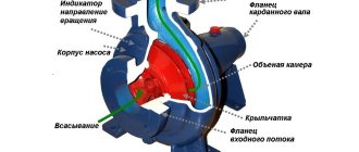
All vacuum pumps operate on the same main principle, displacement. When a substance is pumped out with a vacuum pump, the volume of the working chamber changes. The design of a liquid ring type vacuum pump is as follows :
- The shape of an industrial pump is usually cylindrical;
- Inside the working chamber there is a specific shaft with a wheel called an impeller. This unit is a key part of the entire unit;
- The wheel, when rotating in the body of the device, captures water with its blades, resulting in a centrifugal force that causes water to spread along the walls of the working chamber;
- A specific water ring is formed from the working fluid, and a vacuum is formed inside.
After the pump is started, it will begin to draw in air or gas, and then send the purified flows in the desired direction.
Rotary vane type vacuum pumps operate according to a different scheme, since their design is different. A vacuum pump of this type consists of the following components :
- Housings;
- Entry and exit;
- Blades;
- Special rotor.
The exhaust valve is equipped with an oil seal. The rotor blades divide the working chamber into two compartments. When the pump is turned on, gas will begin to flow into the expansion chamber.
Separation by operating principle
- Vortex installation. The device has a high suction capacity, but is completely unsuitable for pumping dirty water, since it is overly sensitive to suspended particles. The vacuum in the installation is created during the rotation of the wheel with blades.
- Centrifugal view. The operation of the unit is associated with the creation of centrifugal force. It arises from the action of the wheel blades, creating the required liquid pressure.
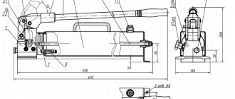
- Hand pump. We are talking about the simplest and most budget option, since physical effort is enough for its operation. The device can be vane or piston.
- Vibration type. The main element of this pumping equipment is an electromagnet. It affects the movement of the armature, which is built into it, and the piston. When oscillating, excess liquid is pushed out. The main advantage of the installation is the absence of an electric motor and rotating elements.
Vacuum pump, application area
The advent of vacuum pumps has made it possible to simplify various technological processes that require a vacuum environment. Vacuum pumps are used in the following industries :
- Protect the environment. This is an extremely broad area, since many industries have special treatment facilities and containers that purify the breakdown products of harmful substances;
- Printing production. Vacuum pumps of various types are used to prepare, copy and scan images;
- In the food industry, the demand for vacuum pumps is extremely high. They are used for processing and vacuum packaging of various products;
- In the medical industry. Mini-vacuum devices are especially popular in medicine;
- In the chemical industry, vacuum pumps for the distillation of substances and decomposition products are in great demand. Many processes in the modern chemical industry cannot be imagined without the use of vacuum systems;
- Vacuum containers are often used in glass and ceramics production;
- Woodworking industry.
In addition to industry, vacuum pumps are used in agriculture, and even in everyday life.
Vacuum water pumps and their characteristics
Water vacuum pumps are extremely popular in industry. They are durable, easy to maintain and have a wide range of capabilities. The main technical characteristics of vacuum pumps of this type are as follows :
- The pumping speed depends on the power of the vacuum pump motor. Most modern models are capable of providing pumping speeds from 1.1 m3 per minute to 12 or more m3 per minute;
- The motor power of vacuum water pumps varies from 4 to 40 kW, although more powerful motors are also available;
- The dimensions of vacuum pumps depend on the performance of the units;
- The average weight of pumps of this type starts from 25 kg and ends at 2,000 kg. Although there are also heavier pumps.
Now vacuum water pumps are widely represented on the vacuum equipment market. Many domestic and foreign manufacturers offer their equipment with various characteristics and purposes. Domestic pumps are able to compete with foreign analogues. Thanks to the simplicity of design, durability and high-quality body materials, they can be used in the most difficult conditions and in any industrial and commercial areas.
Popular manufacturers
The most popular installations for wells are from the following companies:
- GRUNFOS. The Danish-German company with extensive experience in manufacturing such types of equipment is one of the world leaders. Everything it produces is characterized by efficiency and high reliability, as well as modern design. Products are created using the latest technologies.
- WILO. A German organization, one of the leaders in the production of pumping equipment on the European market. Offers a wide selection of reliable and simple models. They have high-quality components, are multifunctional, and efficient in operation.
- CALPEDA. Italian products offer quality worthy of the respect of competitors. The company's products are reliable and durable, and offer an excellent price/quality ratio.
Vacuum pump installation
Installing a vacuum unit is not difficult, but you must strictly follow the recommendations in the product data sheet. The basic requirements when installing a vacuum pump are as follows :
- The pump is installed in the driest and cleanest place available in the room;
- The vacuum pump must be installed on a foundation, the mass of which must exceed the mass of the pump by at least 2-3 times;
- The location for the vacuum pump must have open access for various types of work;
- The air temperature in the room where vacuum equipment is installed should be within +5-40 degrees Celsius;
- The unit must be installed horizontally, and there must be a gap between the supporting surface of the pump and the base. All mounting bolts must be tightened until they stop. If this requirement is neglected, the pump will vibrate during operation, which can lead to breakdowns and increased noise levels during operation.
A properly installed vacuum pump will work for a long time without breakdowns. Despite this, visual inspection of vacuum equipment should be carried out daily. Particular attention is paid to the mounting bolts; if they are loose, they must be tightened.
Vane-rotor and plastic-stator vacuum pumps Vane-rotor vacuum pumps - PRVN (with and without lubricant, oil-filled with an oil seal) are produced with a number of plates of four or more. PRVN are designed for pumping air and non-aggressive gases, previously cleaned of mechanical impurities and droplets. PRVNs with an oil seal are usually made with two plates in the rotor, and plate-stator ones - with one plate in the housing. These pumps are designed for pumping air, gases that do not react with oils and the material of pump parts, and steam-gas mixtures that have been previously purified from droplets of moisture and mechanical impurities, as well as for maintaining low and medium vacuum in sealed Volumes.
| φ=0 |
In the cylindrical bore of the housing 1 PRVN (rns. 9.43, a) a cylindrical rotor 2 is located eccentrically. The rotor has grooves into which plates 3 made of metal, asbestos textile or plastic are inserted. When the rotor rotates, the plates, under the action of centrifugal force, come out of the grooves and are pressed against the cylindrical surface of the housing bore. In this case, the crescent-shaped space between the rotor and the cylindrical bore of the housing is divided into separate working cells. When the rotor rotation angle is φ = 180°... O, the volumes of the working cells increase, they are connected to the suction window and filled with the pumped gas. When the volume of the working cell reaches its maximum value, it moves away from the suction window. With further rotation of the rotor, the volumes of the working cells decrease and a process of internal compression occurs in them. When the working cells are connected to the injection port, the injection process begins, during which gas is supplied to the injection pipeline. Vacuum pumps have a bypass channel through which gas from the “dead” volume
| Diagram of a rotary vane vacuum pump |
enters the first compression cell. Gas bypass increases the pumping coefficient and, consequently, the speed of operation of the vacuum pump.
| Rns. (.43. Schemes of PRVN with radial (a) and inclined (6) plates |
PRVN plates are made radial (Fig. 9.43, a) and inclined (Fig. 9.43, b). Making the plates inclined allows you to increase their length, and therefore their service life. reduce the likelihood of the plates jamming in the rotor grooves (from this point of view, the most preferable value of the plate inclination angle is ψ = 8 ... 15°), reduce the power spent on overcoming friction when moving the plates in the housing bore and in the rotor grooves (at ψ = - 8 ... 15° this decrease does not exceed 1...2% and reaches 30...40% at ψ= 40...50°). In the USSR, PRVNs are usually made with radial or inclined plates (with ψ = 8... 15°), with water or air cooling. In oil-filled pumps, oil removes the heat of compression, lubricates rubbing parts and seals gaps. The gas temperature in these pumps is in the range of 333... 373 K. In machines with lubricant, the latter only lubricates the rubbing surfaces. In plastic-rotor vacuum pumps of the oil-filled type, a cylindrical rotor 2 is located eccentrically inside the cylindrical bore of the housing 1 (Fig. 9.441). Two plates 8 and 9 are placed in the groove of the rotor with a spring 7 between them. When the rotor rotates, the plates are pressed against the internal bore of the housing and divide the crescent-shaped cavity between the rotor and the housing bore into two cavities. When the shaft rotates, the volume of one cavity periodically increases and gas is sucked into it: at the same time, the volume of the other cavity periodically decreases and gas compression occurs in it. PRVN perform one and two-stage. In two-stage pumps, to reduce losses between the first and second stages, they are connected by channel a. Valve 6 a of the discharge line of the second stage o is loaded into the main oil reservoir U. In two-stage pumps, the geometric dimensions of the stages are the same, but the plates are offset from one another ia 90°/ In plastic stator pumps, plate 3 (Fig. 9.45) moves back and forth in the groove of the housing /, is pressed against rotor 2 by lever mechanism 5 and divides the crescent-shaped cavity between rotor 2 and housing 1 into two working cells. Gas is sucked through the inlet pipe 4, which is blocked by the rotor. When inlet 4 is open, gas enters the working cell during approximately one rotation of the rotor. When the inlet pipe is separated from the working cell, gas compression occurs in it. When the difference in gas pressure in the working cell and in the discharge pipe exceeds the pressure loss in valve 6, the latter will open and the gas will be forced out into the discharge pipe. A characteristic feature of plate-stator and. oil-filled rotary vane vacuum pumps - the presence of oil in the working cavities, filling the gaps and preventing the flow of gas through them. In addition, the valves of these pumps operate under oil filling, which increases their tightness, practically reduces dead volumes to zero, and increases the speed of the pumps and the vacuum created. Oils used for pumps must have a certain viscosity both at room temperature, so as not to impede its start-up, and at operating temperature (333 ... 343 K), at which lubricity should not deteriorate. In addition, oils should not oxidize and decompose at operating temperature and affect pump parts; The oil vapor pressure must be low for the pump to provide a low residual pressure limit. When the vacuum pump is started, oil is often thrown into the suction line; after stopping
| Rice. v.45. Diagram of a vane-stator vacuum pump |
pump, if pressure equality in the suction and discharge pipes is not ensured, oil under atmospheric pressure can be squeezed out into the vacuum system. In this regard, solenoid valves 4 and 3 are installed at the suction pipe 5 (see Fig. 9.44). Typically, a limited amount of oil is poured into the pumps, so to protect against oil being thrown into the vacuum system, you can also use a safety container provided directly in or outside the pump. When the pump stops, the oil is squeezed into this container. It is possible to provide containers with a float valve on the suction pipe of the pumps. When oil is forced into this container, it lifts a float valve, which shuts off the vacuum system. However, due to limited volumes, such a protection system is not reliable enough. Sometimes it is necessary to use a pump with an oil seal to pump out vapors that are sparingly soluble in oil (for example, water), easily soluble in oil (trichlorethylene), and vapors or gases that chemically interact with the vacuum pump oil. When pumping out vapors that are limitedly soluble in oil, at each compression stroke, when the pressure in the working cell reaches the vapor saturation pressure at a given temperature, the vapors condense. The resulting condensate, together with the oil, is discharged into the main oil tank 10 (see rns. 9.44). As the oil in the main reservoir becomes contaminated with condensate, more and more of it enters the vacuum pump. Here, the condensate on the suction side evaporates and creates a back pressure that prevents new portions of the mixture of steam and gas from entering the pump. In addition, due to the formation of water-oil emulsin, lubrication of friction surfaces deteriorates, which leads to rapid wear. When pumping out vapors that are easily soluble in oil, not only condensate dissolves, but steam also dissolves. In this case, steam and condensate are evenly distributed in the oil of the main tank and do not settle to the bottom, as happens when pumping out water vapor. When pumping out gases and vapors that react with oils, sludge, sediment, etc. are formed.
Diffusion pumps
Operating principle. Diffusion pumps are used for pumping vacuum systems to residual pressures of 10-1 ... Ι0″5 Pa and below. At such pressures, the free path length of the molecules of the pumped gas is almost always greater than the diameter of the pump inlet, so a molecular regime of gas flow arises in it.' Thermal movement through the pump inlet directs gas molecules towards the steam jet. The mechanism of gas removal in diffusion pumps is determined by diffusion processes. Under the influence of the difference in gas concentrations above the steam jet and in the jet, the concentration of gas in the jet near the nozzle is negligible, resulting in gas diffusion into the jet. Once in the jet, the gas molecules receive impulses from the steam molecules in the direction of the steam flow and are carried away along with the jet to the wall of the pump housing: therefore, the steam condenses on the cooled wall, and the gas is compressed in the jet to the outlet. stage pressure flows along the wall into the space above the next 10®” stage of the suction pump. Along with the direct diffusion of gas, a reverse diffusion of gas also occurs from the side of the forevacuum. So in this case, gas molecules moving in the opposite direction collide with vapor and gas molecules moving towards them; Only a small part of the ph10 molecules diffuse back through the structural direction in the forvacuum direction. The number of gas molecules diffusing through the jet in the opposite direction, under optimal operating conditions of the pump, is immeasurably small compared to the number of gas molecules diffusing into the jet from the side of the inlet pump. However, in some cases. For example, when pumping light gases with a pump whose operating mode is optimal for pumping air, the influence of reverse diffusion can significantly affect the characteristics of the pump. Pump design. Diffusion pumps, like booster pumps, are multistage systems with inverted umbrella-type nozzles. Depending on the type of working fluid used in the pump, modern diffusion pumps are divided into steam-oil and steam-mercury. In oil-steam pumps, various working fluids of organic origin with low steam pressure at normal temperature are used. As a rule, these are mixtures of fractions with different vapor pressures and molar masses. In this regard, it should be noted that the requirements for the working fluid of steam-oil pumps, which provide the most favorable operating conditions for individual stages, are different. Thus, for the operation of the first (input) stage, which determines the maximum residual pressure and the speed of the pump, a working fluid with low vapor pressure at normal temperature is needed (to obtain a low residual pressure) and. at operating temperature in the boiler. This is due to the need to create a low-density Var jet to ensure a high rate of gas diffusion into the jet). For the last (outlet) stage, which determines the highest outlet pressure, the steam pressure at normal temperature is unimportant, and the pressure is the same at the operating temperature. , the boiler should be possible - flatter to obtain a jet of high density. Taking this into account, some modern steam-oil pumps provide for fractionation of the working bone in the pump itself. Wherein
| Diagram of a steam-oil fractionating diffusion pump: / - oil deflector; 2 - steam line; 3 - body; 4—protected casing; b - electric heater; 6 — ejector nozzle; 7 — ejector confuser; 8 and 9 - inlet and outlet flanges |
heavy fractions with low vapor pressure are sent to the first stage, and light fractions with high vapor pressure are sent to the last stage. Such systems are called fractionating. A diagram of a typical steam-oil three-stage fractionating diffusion pump is given in Fig. 10.25. The first two stages of the pump are umbrella type, the third stage is ejector. To fractionate the working fluid, the pipes supplying steam to the stages are separated in the pump, and a special labyrinth formed by fractionating rings is installed on the bottom of the pump. The oil condensate flowing down the wall of the pump housing 3 into the boiler inc. enters through the slots in the lower part of the outer steam line into the space between the outer and inner pipes; passing through the labyrinth in the fractionating device, the working fluid evaporates, becoming depleted as it moves towards the inner pipe, in light fractions with high vapor pressure. The heavier part of the working fluid, consisting of fractions with low vapor pressure, enters the inner pipe and is directed to the first, high-vacuum stage,
| Rice.' 10.26. Diagram of an air-cooled vapor-oil diffusion* pump |
and the light fractions enter the second and ejector stages. Pump housing 3 and oil deflector I are cooled with water. In some cases, for example in mobile installations, water-cooled pumps are inconvenient to use; then use pumps with forced air cooling (Fig. 10.26). The pump is cooled by fan I installed on housing 2 for more efficient cooling.
| Single stage glass mercury steam pump: |
/ ■" trap; 2 - nozzle; 3 - heater; 4 - thermal insulation of the fins on the body of the vacuum pump. The main structural materials of steam-oil pumps are aluminum (steam line parts, nozzles) and low-carbon or corrosion-resistant steel (housing). Steam-mercury pumps are structurally different from steam-oil pumps, which is due to the properties of mercury as a working fluid. Firstly, mercury is a homogeneous LIQUID, not. changing the cabbage soup's composition in the boiling water of the pump; Therefore, mercury steam pumps do not have fractionating devices and all stages of the pump are supplied with steam of the same composition. Secondly, mercury is chemically active, which determines the choice of construction materials for the pump. “··' - One of the most common mercury steam pumps, used mainly in laboratory conditions, is a single-stage glass pump (Fig. 10.27), very simple in design. Nozzle 2 is made pylindrical. Such pumps with different sizes and characteristics are usually manufactured by the consumer. In the metal steam-mercury three-stage pump I-50R (Fig. 0.28), the confuser of the last ejector stage simultaneously serves as a pipe connecting the pump to the output disk trap. Due to the fact that 4fo the vapor pressure of mercury at the nominal temperature is high (OL Pa), in order to obtain a high vacuum in the evacuated vessel, it is necessary to install a trap cooled to a low temperature between the pyagortium pump and the evacuated vessel. When using a trap cooled by liquid Nitrogen, a low-temperature pump makes it possible to obtain in a well-degassed system T - 723 K system p„ = 10~10 Pa. Working fluids. Mercury has a number of advantages that have led to its use as a working fluid in high-vacuum pumps: homogeneity of composition; stability of properties during operation in the pump (mercury does not decompose at operating temperatures); resistance to oxidation air0-] high pressure at high temperature in the boiler - grass and * very low solubility of gases. Disadvantages of mercury: high vapor pressure (0.1 Pa) at normal temperature (to obtain a pressure below 0.1 Pa in the pumped-out vessel, it is necessary to install a trap cooled to a low temperature between the pump and the vessel); high chemical activity towards metals (mercury forms amalgams with most metals, which limits the choice of construction materials for the pump); toxicity of vapors (it is necessary to create special rooms for working with mercury and take precautions to prevent an increase in the concentration of mercury vapors in work areas). Mercury intended for use in pumps must be well cleaned. The indicated disadvantages of mercury, especially the toxicity of vapors, significantly limit the possibility of its use as a working fluid in pumps. Mercury pumps are used mainly for pumping systems in which mercury vapor is the working medium (mercury rectifiers, lamps), and in installations where high purity of the working medium is required (in mass spectrometers, ultra-high vacuum systems of thermonuclear installations, etc.). High-vacuum oils do not have these disadvantages. They are chemically inert, non-toxic, and have a low vapor pressure at normal temperature, allowing one to obtain a maximum residual pressure of 10-4 ... i0~5 Pa and below without the use of low-temperature traps. In high-vacuum steam-oil pumps, four types of working fluids are mainly used: mineral oils; organosilicon compounds; esters of organic alcohols and acids; synthetic hydrocarbon fluids. Mineral oils are obtained by vacuum distillation of petroleum products. These are liquids that are heterogeneous in composition, representing mixtures of hydrocarbons with different molecular weights and temperatures.
| Three-stage small-sized steam-mercury pump I-60R: 1— housing; 2 - steam line; 3 - ejector; 4 - boiler; 5 — heat-insulating casing; 6 - heater; 7 - trap for mercury vapor |
boiling systems, characterized by low vapor pressure at normal temperature. Pumps operating on these oils create a maximum residual pressure of 10~4 ... 10~6 Pa. Mineral oils, as a rule, have fairly high heat resistance and relatively low thermal-oxidative stability (when oxidized, they form a resinous deposit on the internal surfaces of the pump). Despite the high thermal stability of mineral oils, the composition of residual gases in a well-trained pump is largely determined by the products of oil decomposition in the pump boiler. The spectrum of residual gases (Fig. 10.29) in a pump running on mineral oil contains a significant amount of heavy hydrocarbons. Despite their low thermal-oxidative stability and the formation of volatile hydrocarbons, mineral oils are the most widely used due to their relatively low cost (compared to other working fluids). The domestic industry produces high-drying mineral oils VM-1 and VM-5, which are products of distillation of medical azelin oil; the cheapest oil (VM-1) is obtained by single distillation, and VM-5 oil by double distillation of vaseline oil. VM-5 oil has a more homogeneous composition and higher thermal resistance compared to VM-1 oil. The maximum residual pressure of the pump when operating in VM-5 oil is an order of magnitude lower than when operating in VM-1 oil, and the time to achieve residual pressure is 1.5 times less. It should be noted that the characteristics of mineral oils depend on the type of oil used and the quality of the feedstock.
Synthetic hydrocarbon liquids are more expensive than mineral ones, but their production does not require scarce raw materials (oil); their compositions and characteristics are exactly reproducible. The synthetic hydrocarbon liquid Alkaren-24 is an alkyl-hydrocarbon liquid that has a low vapor release at normal temperature, which makes it possible to obtain a maximum residual pressure of the diffusion pump of 10~® ... 10-7 Pa, and is superior to mineral oils in thermal-oxidative resistance. Silicone organic liquids are polysiloxane compounds, the molecules of which consist of alternating silicon and oxygen atoms, with hydrocarbon radicals attached to free silicon atoms. Due to the strong bond between silicon and oxygen, organosilicon liquids have high thermal and thermal oxidation resistance. The entry of atmospheric air into the pump does not, as a rule, affect the operational properties of the working fluid. Organosilicon liquids are inert to iodine. Our focus is the industrial production of high-vacuum silicone liquids PES-V-1 and PES-V-2 (narrow fractions of polyethylsiloxane liquid), as well as PFMS-2/5l (narrow fraction of polyphenylmethylsiloxane liquid). Industrial production of liquid 133-38 is being mastered
| and, mv |
| Rice. 10.29. Spectrum of residual gases in the diffusion axis when operating on VM-5 oil (U is the reading of the output device) |
(PFMS-13) - a mixture of methylphenylsiloxane, oxidative stability and 1.5 times superior to the PFMS-2/5l liquid and intended to replace the latter. Liquid 133-35 (MFT-1), methylphenylpiclotetrasiloxane, has even greater oxidative stability; In terms of thermal-oxidative resistance, it is 2 ... 3 times superior to liquid 133-38. These liquids have low vapor pressure at normal temperatures and allow the maximum residual pressure of a diffusion pump to be obtained up to 10-4 Pa. In diffusion pumps designed to obtain ultra-high vacuum, silicone liquids FM-1 (pentafeyl-trisiloxane) and FM-2 are used (hexaphenyl-tetrasiloxane), which have ultra-low vapor pressure at normal temperature (10“® ... 10″11 Pa) and make it possible to create a maximum residual pressure of the diffusion pump below 10-7 Pa without the use of liquid nitrogen-cooled tanks. In terms of thermal-oxidative resistance, FM-1 and FM-2 Liv® liquids are slightly inferior to liquid 133-35. The ethers used as working fluids in domestic* diffusion pumps are polyphenyl compounds that are exceptionally thermally stable. The industry produces high-high-vacuum working fluids 5F4E with a steam pressure at normal temperature of about W~v Pa and M-5F4E' with a steam pressure of 10~10 Pa; The maximum residual pressures created by the diffusion pump when working on these liquids are δ-ΙΟ-* and 5-10″8 Pa, respectively. There are practically no heavy hydrocarbons in the spectrum of residual gases. In terms of thermal oxidation resistance, esters are superior to mineral oils, but inferior to organosilicon liquids FM-1 and FM-2. The disadvantages of ethers are their relatively high pour point (277.4 K) and crystallization on cold surfaces. . Industrial production of non-crystallizing polyphenylene liquid V-PFE with a pour point below 273 K and a vapor pressure at normal temperature of about 10~10 Pa has been mastered. In diffusion pumps intended for pumping out corrosive gases (oxygen, halogens, halogen-containing compounds, etc.), high-vacuum working fluid MIA based on perfluoropolyethers can be used. Firefighting liquid is explosion-proof. The main characteristics of working fluids of diffusion pumps are given in Table. 10.6. Characteristics of diffusion pumps. In the operating pressure range, the speed of action of the diffusion pump does not depend on the inlet pressure (rns. 10.30, section //) and decreases in the region of low (section /) and high (section III) pressures. The decrease in speed of action at low pressures is due to the fact. that in this region reverse diffusion of gas through the steam jet is manifested. In addition, the gases carried away with the steam jet from the boiler of the Pump and released by the walls of the pump begin to play a significant role. When a steam jet condenses on the pump, a certain amount of gas, compressed by it to high pressure (especially in the foreva-Numa region), dissolves in the condensate and enters with the gas and the boiler.
| Rns. 10.30. Dependence of the speed of action of the diffusion pump on the inlet pressure |
nickname iasos. This gas, along with reverse diffusion and gas separation from the walls of the pump, largely determines the maximum residual pressure p0 of the pump and reduces the speed of action S. At p - p0, the speed of action S = 0. As the inlet pressure increases, the mass of gas removed by the pump from the pumped vessel increases compared to the mass of gas returned due to anti-diffusion, gas separation and a stream from the boiler. When these masses become incommensurable, the speed of action ceases to depend on the inlet pressure (section II). As the inlet pressure increases, the outlet pressure of the pump increases, regulated by the speed of the foreline pump. An increase in outlet pressure leads to the appearance of a shock wave in the jet, its movement to the nozzle and separation of the jet from the walls of the pump, accompanied by a flow of gas from the forevacuum region to the high-vacuum region. In this case, the speed of action of the pump is reduced to the speed of action of the foriacuum pump. The speed of the pump depends on the power of the heater, the type of gas being pumped out and its temperature, and the type of working fluid.