The Z connection filter is designed for connecting high-frequency protection posts.
Schemes for connecting the meter through current transformers For correct metering of electricity using CTs, it is necessary to observe the polarity of connecting their windings: the beginning and end of the primary are designated L1 and L2, the secondary - I1 and I2. We load each of the windings in turn with an active load, which can be anything, for example, incandescent lamps of various power and voltage; an incandescent lamp with a power of 40 watts per volt voltage has an active resistance Ohm in the cold state, a lamp with a power of watts - 30 Ohms, wire-wound resistors , nichrome spirals from electric stoves, rheostats, etc. Personnel safety was described. The phase is supplied to one end, the consumer is connected to the other. HOW IS THE TRANSFORMER DESIGNED? HOW TO CHECK THE SERVICEABILITY OF A TRANSFORMER
The pollutant barrier does not allow high frequency currents to pass into the voltage transformer. These vectors would determine the magnitude of the magnetic fluxes in the three rods, since the electromotive forces are proportional to the fluxes that caused them.
Cast resin voltage transformers are increasingly being used.
The current transformer is a universal product; details should be looked for on the body and nameplate of third-party equipment. This is all clear and I always used to ground the secondary circuit when connecting any types of meters, see
The circuit allows you to measure all line and phase voltages and monitor insulation in systems with an isolated neutral. Deciphered according to GOST Why are cascade type CTs manufactured for voltages above kV?
Design and connection of voltage transformer NTMI-10
How to connect a step-down transformer
Most often, the installation of a transformer is required to reduce the voltage. Therefore, how to properly connect a transformer for such a step-down purpose is a question that comes up very often. When connecting this device, the main thing is to choose it correctly in accordance with:
- The magnitude of the input voltage, that is, supplied to the primary;
- The magnitude of the output voltage at the terminals, there can be several of them, depending on the design;
- Power, which depends on the power of consumers.
Connecting a diode bridge to a transformer can be done if there is a need to obtain a constant voltage. Here are diagrams for connecting a diode bridge to a single-phase or three-phase network.
How to choose
The VT we need on the marking should have a designation for input contacts of 220 V, at the output - twelve volts or another voltage according to our requests. Other models may be designed for 380 V, for 2-, 3-phase networks.
When selecting, you need to add up the power of all consumers on the serviced line and compare it with the figure (kVA) for which the transformer is designed, adding 20% of the reserve.
The concept of a group connecting the windings of a three-phase transformer
Three-phase networks use two types of connections: star and delta. When making structures, it may seem that there are only four types of winding arrangements:
- Star-star.
- Star-triangle.
- Triangle-star.
- Triangle-triangle.
In reality, everything is more complicated, since in each type of connection (star or triangle) the parts of the windings can be connected differently. An example is a conventional two-winding transformer. If such a device has the same beginnings and ends of the windings, then the phase shift will be equal to 0. Turning one of the windings will give a phase shift of 180.
There are also z-shaped winding connections (zigzag). In such designs, each of the windings consists of two parts located on different cores of the transformer magnetic circuit.
A three-phase network is characterized by a phase shift relative to one another by 120. Therefore, there are a total of 12 connection groups. Each group is characterized by a certain shift of the same phases at the input and output of the transformer.
Connection diagrams
Connection diagrams for single-phase voltage transformers:
Connection diagrams for three-phase voltage transformers:
Diagrams and groups of connections of windings of three-phase three-winding transformers with main and additional secondary windings
Also read: Three-phase oil transformer - TMF
General information
Voltage transformers are used to convert high voltage to low standard values (100, 100/√3, 100/3 V), used to power measuring instruments and various control, protection and automation relays. They, like current transformers, isolate (separate) measuring instruments and relays from high voltage, ensuring the safety of their service.
According to the design principle, switching circuit and operating features, electromagnetic voltage transformers differ little from power transformers. However, compared to the latter, their power does not exceed tens or hundreds of volt-amperes. At low power, the operating mode of voltage transformers approaches the idle mode. Opening the secondary winding of a voltage transformer does not lead to dangerous consequences.
At voltages up to 35 kV, voltage transformers, as a rule, are switched on through fuses so that if the voltage transformer is damaged, it does not cause an accident. At voltages of 110 kV and above, fuses are not installed, since, according to available data, damage to such voltage transformers rarely occurs.
Voltage transformers are switched on and off using disconnectors.
To protect the voltage transformer from short circuit current, removable tubular fuses or overcurrent circuit breakers are installed in the secondary circuits. Fuses are installed if the voltage transformer does not supply high-speed protection, since these protections may act falsely if the fuse-link does not burn out quickly enough. The installation of automatic circuit breakers ensures the effective operation of special interlocks that disable certain types of protection in the event of a break in voltage circuits.
For safe maintenance of secondary circuits in the event of an insulation breakdown and high voltage entering the secondary winding, one of the secondary winding terminals or the zero point is connected to ground. In circuits for connecting secondary windings in a star, it is not the zero point that is grounded, but the beginning of the phase b winding. This is explained by the desire to reduce the number of switching contacts in secondary circuits by 1/3, since the grounded phase can be supplied to the relay in addition to switches and auxiliary contacts of disconnectors.
Rice. 4.1. Diagrams of voltage transformers of types NKF-110 (a), NKF-220 (b): VN – primary winding; NN – secondary windings; P – equalizing windings; P – connecting windings; M – magnetic circuit; U f – phase voltage
When using voltage transformers to power AC operational circuits, it is allowed to ground the zero point of the secondary windings through a breakdown fuse, which is caused by the need to increase the insulation level of the operational circuits.
While work is being carried out directly on the voltage transformer and its busbar, safety rules require the creation of a visible break not only from the high voltage side, but also from the secondary circuits, in order to avoid the appearance of voltage on the primary winding due to the reverse transformation of voltage from the secondary circuits powered from which - or another voltage transformer.
To do this, switches are installed in the secondary circuits of the voltage transformer or removable fuses are used. Disabling circuit breakers, as well as breaking secondary circuits with auxiliary contacts of disconnectors, do not provide a visible break in the circuit and are therefore considered insufficient.
Where can I get the original transformer?
The easiest way is to pick up a ready-made transformer on the radio market, if, of course, it is available in your city. There you can also agree on rewinding the transformer. But both transformers and services for rewinding them are quite expensive.
The picture shows part of a tray at a radio market where you can buy transformers in the city of Cishinau (Chisinau).
If you have some unnecessary equipment lying around in your barn or on your balcony, then there are probably transformers in it. Any dismountable network transformer is very easy to modify to suit your needs. The most important thing is that its overall power is enough.
If the power of the transformer is less than required, then under load the output voltage of the transformer may drop significantly. But this is also not a problem, since microcircuits such as TDA2030, TDA2040 and TDA2050 can operate with a significant reduction in supply voltage, namely: ±6, ±2.5 and ±4.5 Volts, respectively.
It is unlikely that the secondary windings of the found transformer will be suitable for current and voltage, but the primary winding is already designed for the voltage of the lighting network and this is the best help, since it is much easier to rewind the secondary winding than the primary.
Well, if this is a standard unified transformer, then by its name you can accurately determine the voltages and maximum permissible currents of the secondary windings. Such transformers cannot be disassembled, so before buying one, you need to check the name with the data in the directory.
At the end of the article there is a link to a reference book in which you can find detailed information about most unified transformers of Soviet and post-Soviet production.
If it is a transformer without identification marks, then the probability that it will have to be rewound will tend to 99%. It's not worth paying a lot for such a trans.
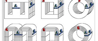
When purchasing a transformer with a ring magnetic core, you should keep in mind that not every transformer can be disassembled without damaging the primary winding.
- Suitable for replacing the secondary winding.
- It is necessary to wind the primary winding.
- It is necessary to wind the primary winding.
Return to top menu
Voltage transformer design
Like all transformers, as mentioned above, this type of transformer has both primary windings (high voltage) and secondary windings (low voltage). There are single-phase and three-phase voltage transformers.
Each of them has a magnetic circuit, which is subject to fairly high requirements. The fact is that the greater the dissipation of the magnetic flux in such a transformer, the greater the measurement error. By the way. Depending on the error, transformers are classified into different accuracy classes (0.2; 0.5; 1; 3). The higher the number, the greater the measurement error.
For example, a transformer with an accuracy class of 0.2 can allow an error of no more than 0.2% of the measured voltage value, and, accordingly, an accuracy class of 3 - no more than 3%.
The designations on the diagrams and the natural design can be very different from each other.
A single-phase two-winding transformer is shown in the figure as it actually looks.
We recommend studying Magneto. device and operation. types and applications
In the diagrams it is designated as:
Please note that the transformer is a step-down, there are fewer turns in the secondary winding than in the primary, and this is reflected visually in the diagram in this case, although this is not always done. In addition, the beginnings and ends of the windings are indicated on the diagram and on the transformer itself
Primary windings are designated by large (capital) letters A and X. Secondary - small (lowercase) letters a and x.
There are also three-winding single-phase transformers that have two secondary windings. One of which is the main one, and the second is additional. The additional winding serves to control insulation and has the abbreviation KIZ. The markings of the terminals of this winding are as follows: ad - the beginning of the winding, xd - the end of the winding.
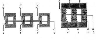
Three-phase transformers are available with two types of magnetic cores: three-rod and five-rod.
Beginnings and endings are designated slightly differently here. On the primary windings, the beginnings are designated by the letters A, B and C according to the phases to which they will be connected, and the ends by the letters X, Y and Z. The secondary windings, respectively, by small letters a, b, c and x, y, z.
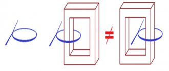
The magnetic fluxes created by the AX, BY, CZ coils compensate each other under normal operating conditions. But in the event of a breakdown of one of the phases to the ground, too much imbalance is created in the magnetic cores and part of the flux will be looped through the air, which creates strong heating of the transformer due to an increase in the rated current in the windings. Additional rods are precisely designed to take over the resulting unbalanced flows and prevent overheating of the transformer. At the same time, additional windings are wound in it, but more on that later.
We connect an unknown transformer to the network.
Nikolay Petrushov
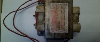
How to deal with the windings of a transformer, how to properly connect it to the network and not “burn it” and how to determine the maximum currents of the secondary windings??? Many beginning radio amateurs ask themselves these and similar questions. In this article I will try to answer such questions and, using the example of several transformers (photo at the beginning of the article), to understand each of them.. I hope this article will be useful to many radio amateurs.
First, remember the general features for armored transformers
— The mains winding, as a rule, is wound first (closest to the core) and has the highest active resistance (unless it is a step-up transformer, or a transformer with anode windings).
— The network winding may have taps, or consist, for example, of two parts with taps.
— The serial connection of windings (parts of windings) for armored transformers is carried out as usual, beginning to end or terminals 2 and 3 (if, for example, there are two windings with terminals 1-2 and 3-4).
- Parallel connection of windings (only for windings with the same number of turns), the beginning is made as usual with the beginning of one winding, and the end with the end of another winding (n-n and k-k, or pins 1-3 and 2-4 - if for example there are identical windings with pins 1-2 and 3-4).
General rules for connecting secondary windings for all types of transformers.
To obtain different output voltages and load currents of windings for personal needs, different from those available on the transformer, can be obtained by various connections of the existing windings to each other. Let's consider all possible options. — Windings can be connected in series, including windings wound with wires of different diameters, then the output voltage of such a winding will be equal to the sum of the voltages of the connected windings (Utotal = U1 + U2... + Un). The load current of such a winding will be equal to the smallest load current of the available windings. For example: there are two windings with voltages of 6 and 12 volts and load currents of 4 and 2 amperes - as a result, we get a common winding with a voltage of 18 volts and a load current of 2 amperes. — Windings can be connected in parallel only if they contain the same number of turns
, including those wound with wires of different diameters.
The correct connection is checked like this. We connect two wires from the windings together and measure the voltage on the remaining two. If the voltage is doubled, then the connection was not made correctly, in this case we change the ends of any of the windings. If the voltage at the remaining ends is zero or so (a difference of more than half a volt is not desirable, the windings in this case will heat up at XX), feel free to connect the remaining ends together. The total voltage of such a winding does not change, and the load current will be equal to the sum of the load currents of all windings connected in parallel. (Itotal = I1 + I2… + In) . For example: there are three windings with an output voltage of 24 volts and load currents of 1 ampere each. As a result, we get a winding with a voltage of 24 volts and a load current of 3 amperes. — The windings can be connected in parallel-series (for features for parallel connection, see the paragraph above). The total voltage and current will be the same as in a series connection. For example: we have two series and three parallel connected windings (examples described above). We connect these two component windings in series. As a result, we get a common winding with a voltage of 42 volts (18+24) and a load current along the smallest winding, that is, 2 amperes. — The windings can be connected back-to-back, including those wound with wires of different diameters (also parallel and series-connected windings). The total voltage of such a winding will be equal to the difference in voltages of oppositely connected windings, the total current will be equal to the smallest winding load current. This connection is used when it is necessary to reduce the output voltage of the existing winding. Also, in order to reduce the output voltage of any winding, you can wind an additional winding on top of all the windings with a wire, preferably no smaller in diameter than the winding whose voltage needs to be reduced, so that the load current does not decrease. The winding can be wound without even disassembling the transformer, if there is a gap between the windings and the core, and it can be connected opposite the desired winding. For example: we have two windings on a transformer, one is 24 volts 3 amperes, the second is 18 volts 2 amperes. We turn them on oppositely and as a result we get a winding with an output voltage of 6 volts (24-18) and a load current of 2 amperes. But this is purely theoretical, in practice the efficiency of such a connection will be lower than if the transformer had one secondary winding. The fact is that the current flowing through the windings creates an EMF in the windings, and in a larger winding the voltage decreases in relation to the voltage XX, and at less - increases, and the greater the current flowing through the windings, the greater this effect.
As a result, the total rated voltage (at rated current) will be lower. Let's start with a small transformer, adhering to the features described above (left in the photo). We examine it carefully. All its terminals are numbered and the wires fit to the following terminals; 1, 2, 4, 6, 8, 9, 10, 12, 13, 22, 23, and 27. Next, you need to test all the terminals with an ohmmeter to determine the number of windings and draw a diagram of the transformer. The following picture emerges. Pins 1 and 2 - the resistance between them is 2.3 Ohms, 2 and 4 - between them is 2.4 Ohms, between 1 and 4 - 4.7 Ohms (one winding with a middle pin). Further 8 and 10 - resistance 100.5 Ohms (another winding). Pins 12 and 13 - 26 Ohm (another winding). Pins 22 and 23 - 1.5 Ohm (last winding). Pins 6, 9 and 27 do not communicate with other pins or with each other - these are most likely screen windings between the network and other windings. These terminals in the finished design are interconnected and attached to the housing (common wire). Let's carefully inspect the transformer again. The network winding, as we know, is wound first, although there are exceptions.
It's hard to see in the photo, so I'll duplicate it. A wire coming from the core itself is soldered to pin 8 (that is, it is closest to the core), then a wire goes to pin 10 - that is, winding 8-10 is wound first (and has the highest active resistance) and is most likely network. Now, based on the data received from the dialing, you can draw a diagram of the transformer.
All that remains is to try to connect the supposed primary winding of the transformer to a 220 volt network and check the no-load current of the transformer. To do this, we assemble the following chain.
In series with the intended primary winding of the transformer (for us these are pins 8-10), we connect an ordinary incandescent lamp with a power of 40-65 watts (for more powerful transformers 75-100 watts). In this case, the lamp will play the role of a kind of fuse (current limiter), and will protect the transformer winding from failure when connected to a 220 volt network, if we have chosen the wrong winding or the winding is not designed for a voltage of 220 volts. The maximum current flowing in this case through the winding (with a lamp power of 40 watts) will not exceed 180 milliamps. This will protect you and the transformer being tested from possible troubles.
-And in general, make it a rule that if you are not sure about the correct choice of the network winding, its switching, or the installed winding jumpers, then always make the first connection to the network with an incandescent lamp connected in series.
Being careful, we connect the assembled circuit to a 220 volt network (I have a slightly higher network voltage, or rather 230 volts). What do we see? The incandescent lamp does not light. This means that the network winding has been selected correctly and further connection of the transformer can be made without a lamp. We connect the transformer without a lamp and measure the no-load current of the transformer.
The no-load current (OC) of the transformer is measured as follows; a similar circuit is assembled that we assembled with a lamp (I won’t draw it anymore), only instead of the lamp an ammeter is turned on, which is designed to measure alternating current (carefully inspect your device for the presence of such a mode). The ammeter is first set to the maximum measurement limit, then, if there is a lot of it, the ammeter can be transferred to a lower measurement limit. Being careful, we connect to a 220 volt network, preferably through an isolation transformer. If the transformer is powerful, then at the moment the transformer is connected to the network, it is better to short-circuit either with an additional switch, or simply short-circuit with each other, since the starting current of the primary winding of the transformer exceeds the no-load current by 100-150 times and the ammeter may fail. After the transformer is connected to the network, the ammeter probes are disconnected and the current is measured.
The no-load current of the transformer should ideally be 3-8% of the rated current of the transformer. It is considered normal that the current is 5-10% of the rated value. That is, if a transformer with a calculated rated power of 100 watts, the current consumption by its primary winding is 0.45 A, then the XX current should ideally be 22.5 mA (5% of the nominal) and it is desirable that it does not exceed 45 mA (10 % of face value).
As you can see, the no-load current is a little more than 28 milliamps, which is quite acceptable (well, maybe a little too high), since this transformer looks like it has a power of 40-50 watts. We measure the open-circuit voltage of the secondary windings. It turns out at terminals 1-2-4 17.4 + 17.4 volts, terminals 12-13 = 27.4 volts, terminals 22-23 = 6.8 volts (this is at a network voltage of 230 volts). Next we need to determine the capabilities of the windings and their load currents. How it's done? If it is possible and the length of the winding wires suitable for the contacts allows, then it is better to measure the diameters of the wires (roughly up to 0.1 mm - with a caliper and accurately with a micrometer), and according to the table HERE, with an average current density of 3-4 A/mm.sq. — we find the currents that the windings are capable of producing. If it is not possible to measure the diameters of the wires, then proceed as follows. We load each of the windings in turn with an active load, which can be anything, for example, incandescent lamps of various power and voltage (an incandescent lamp with a power of 40 watts at a voltage of 220 volts has an active resistance of 90-100 Ohms in a cold state, a lamp with a power of 150 watts - 30 Ohm), resistance wires (resistors), nichrome spirals from electric stoves, rheostats, etc. We load until the voltage on the winding decreases by 10% relative to the no-load voltage. Then we measure the load current.
This current will be the maximum current that the winding is capable of delivering for a long time without overheating.
The voltage drop is conventionally accepted to be up to 10% for a constant (static) load in order to prevent the transformer from overheating. You may well take 15%, or even 20%, depending on the nature of the load. All these calculations are approximate. If the load is constant (incandescent lamps, for example, a charger), then a smaller value is taken, if the load is pulsed (dynamic), for example ULF (except for mode “A”), then a higher value can be taken, up to 15-20%.
I take the static load into account, and I succeeded; winding 1-2-4 load current (with a decrease in winding voltage by 10% relative to the no-load voltage) - 0.85 amperes (power about 27 watts), winding 12-13 (pictured above) load current 0.19-0, 2 amperes (5 watts) and winding 22-23 - 0.5 amperes (3.25 watts). The rated power of the transformer is about 36 watts (rounded to 40). Yes, I also want to talk about the resistance of the primary winding. For low-power transformers it can be tens or even hundreds of Ohms, and for high-power transformers it can be a few Ohms. Very often these questions are asked on the forum; “I measured the resistance of the primary winding of the TC250 with a multimeter, and it turned out to be 5 Ohms. Isn’t it too small for a 220 volt network, I’m afraid to plug it into the network. Tell me, is it normal?” Since all multimeters measure resistance to direct current (active resistance), there is no need to worry, because for alternating current with a frequency of 50 hertz, this winding will have a completely different resistance (inductive), which will depend on the inductance of the winding and the frequency of the alternating current. If you have something to measure inductance with, then you can calculate the winding resistance to alternating current (inductive reactance) yourself. For example; The inductance of the primary winding during the measurement was 6 H, go here and enter this data (inductance 6 H, mains frequency 50 Hz), look - it turned out to be 1884.959 (rounded up to 1885), this will be the inductive reactance of this winding for a frequency of 50 Hz . From here you can calculate the no-load current of this winding for a voltage of 220 volts - 220/1885 = 0.116 A (116 milliamps), yes, you can also add an active resistance of 5 Ohms here, that is, it will be 1890. Naturally, for a frequency of 400 Hz there will be a completely different resistance of this winding.
Other transformers are checked in the same way. The photo of the second transformer shows that the terminals are soldered to contact petals 1, 3, 4, 6, 7, 8, 10, 11, 12. After dialing, it becomes clear that the transformer has 4 windings. The first is on pins 1 and 6 (24 Ohm), the second is 3-4 (83 Ohm), the third is 7-8 (11.5 Ohm), the fourth is 10-11-12 with a tap from the middle (0.1+0.1 Ohm) .
Moreover, it is clearly visible that windings 1 and 6 are wound first (white leads), then comes winding 3-4 (black leads). 24 Ohms of active resistance of the primary winding is quite enough. For more powerful transformers, the active resistance of the winding reaches several Ohms. The second winding is 3-4 (83 Ohms), possibly boosting. Here you can measure the diameters of the wires of all windings, except for winding 3-4, the terminals of which are made of black, stranded, mounting wire.
Next we connect the transformer through an incandescent lamp. The lamp does not light up, the transformer looks like it has a power of 100-120, we measure the no-load current, it turns out 53 milliamps, which is quite acceptable. We measure the open-circuit voltage of the windings. It turns out 3-4 - 233 volts, 7-8 - 79.5 volts, and winding 10-11-12 at 3.4 volts (6.8 with the middle terminal). We load winding 3-4 until the voltage drops by 10% of the no-load voltage, and measure the current flowing through the load.
The maximum load current of this winding, as can be seen from the photograph, is 0.24 amperes. The currents of other windings are determined from the current density table, based on the diameter of the winding wire. Winding 7-8 is wound with 0.4 wire and filament with 1.08-1.1 wire. Accordingly, the currents are 0.4-0.5 and 3.5-4.0 amperes. The rated power of the transformer is about 100 watts.
There is one more transformer left. It has a contact strip with 14 contacts, the top 1, 3, 5, 7, 9, 11, 13 and bottom are even, respectively. It could switch to different mains voltages (127,220,237); it is quite possible that the primary winding has several taps, or consists of two half-windings with taps. We call, and we get the following picture: Pins 1-2 = 2.5 Ohm; 2-3 = 15.5 Ohm (this is one winding with a tap); 4-5 = 16.4 ohms; 5-6 = 2.7 Ohm (another winding with tap); 7-8 = 1.4 Ohm (3rd winding); 9-10 = 1.5 Ohm (4th winding); 11-12 = 5 Ohm (5th winding) and 13-14 (6th winding). We connect to pins 1 and 3 a network with an incandescent lamp connected in series.
The lamp burns at half intensity. We measure the voltage at the terminals of the transformer, it is 131 volts. This means they didn’t guess right and the primary winding here consists of two parts, and the connected part at a voltage of 131 volts begins to enter saturation (the no-load current increases) and therefore the lamp filament becomes hot. We connect pins 3 and 4 with a jumper, that is, two windings in series and connect the network (with a lamp) to pins 1 and 6. Hurray, the lamp is not lit. We measure the no-load current.
The no-load current is 34.5 milliamps. Here, most likely (since part of winding 2-3, and part of the second winding 4-5 have greater resistance, then these parts are designed for 110 volts, and parts of windings 1-2 and 5-6 are 17 volts each, that is, the total for one part 1278 volts) 220 volts was connected to pins 2 and 5 with a jumper on pins 3 and 4 or vice versa. But you can leave it the way we connected it, that is, all parts of the windings in series. This is only better for the transformer. That's it, the network has been found, further actions are similar to those described above.
A little more about core transformers. For example, there is one like this (photo above). What are their common features?
— Rod transformers usually have two symmetrical coils, and the mains winding is divided into two coils, that is, 110 (127) volt turns are wound on one coil, and on the other. The numbering of the terminals of one coil is similar to the other; the terminal numbers on the other coil are marked (or conventionally marked) with a stroke, i.e. 1′, 2′, etc.
— The mains winding, as a rule, is wound first (closest to the core).
— The network winding may have taps, or consist of two parts (for example, one winding - terminals 1-2-3; or two parts - terminals 1-2 and 3-4).
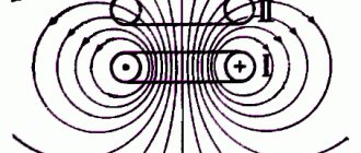
-In a rod transformer, the magnetic flux moves along the core (in a “circle, ellipse”), and the direction of the magnetic flux of one rod will be opposite to the other, therefore, to connect the two halves of the windings in series, contacts of the same name or beginning to beginning (end to end) are connected on different coils ), i.e. 1 and 1′, the network is served on 2-2′, or 2 and 2′, the network is then served on 1 and 1′.
- For a serial connection of windings consisting of two parts on one coil - the windings are connected as usual, beginning to end or end to beginning, (n-k or k-n), that is, pin 2 and 3 (if, for example, there are 2 windings with pin numbers 1-2 and 3-4), also on the other coil. Further serial connection of the resulting two half-windings on different coils, see the paragraph above. (An example of such a connection is in the transformer diagram
). — For parallel connection of windings ( only for windings with the same number of turns
) on one coil the connection is made as usual (n-n and k-k, or pins 1-3 and 2-4 - if, for example, there are identical windings with pins 1-2 and 3-4). For different coils, the connection is made as follows, k-n-tap and n-k-tap, or connect terminals 1-2′ and 2-1′ - if, for example, there are identical windings with terminals 1-2 and 1′-2′ .
Once again, I remind you to follow safety precautions, and it is best to have an isolation transformer at home for experiments with a voltage of 220 volts (a transformer with 220/220 volt windings for galvanic isolation from an industrial network), which will protect against electric shock if you accidentally touch the bare end of the wire .
If you have any questions about the article, or find a transformer in the stash (with suspicion that it is a power transformer), ask questions HERE, we will help you figure out its windings and connection to the network.
Examination
If the transformation ratio is known, then using a voltmeter you can determine the number of the main connection group. For this purpose, voltage is applied to ends A and a or x and y and the voltages are measured at terminals B-c and C-c when connected in a star, or By and Cz when connected in a triangle. The following ratios are used for verification:
UBb = UCc = UAa(k-1) Group Y/Y-0
UBy = UCz = Uxy(k+1) Y/Y-6
UBb = UCc = UAa(√(1-√3k+k2)) Y/∆-11
UBy = UCz = Uxy(√(1+√3k+k2)) Y/∆-5
To avoid equipment damage, emergency situations and injury, all measurements should be made at low voltage, without connecting the equipment to the main network of the enterprise.
Balancing transformer
If the step-down transformer is loaded unevenly, phase imbalance will occur, which is a negatively influencing mechanism. The consequence of such operation and consumption of electrical receivers will be an increase in electricity consumption, and over time, failures and premature destruction of insulation. The safety of eating consumers will be at risk. In order to prevent this, it is necessary to balance the phases through the use of balun transformers.
As can be seen from the diagram, there is an additional winding that must withstand the rated current of one of the phases. It is connected to the break of the neutral conductor, which leads to good results, that is, the symmetrical generation of equal currents in the load.
Transformer types
There are different types of step-down TN. The usual and most common is single-phase for a 220 V network. There are also two- and three-phase for 380 V. The most standard composition: two windings and a laminated core made of electrical steel.
Certain types of VTs are equipped with 1 winding - these are autotransformers, they can also step down / step up. In this case, there are at least 3 conclusions. A 220 V connection is made to one pair of contacts, and the output value is taken from one of the input pairs of terminals and from the other that remains free. But autotransformers cannot be used in wet rooms, since the coils in them are connected, that is, the consumer is also connected to 220 V.
Scheme of operation when one of the transformers is disconnected
In the event that a transformer connected to the supply wire buses is disconnected at the substation, we will have the circuit practically considered in the figure with step-up autotransformers, the role of which is played by the autotransformers closest to the substation in the feeder zones.
At the same time, in the sections from the substation to the autotransformers closest to it we have a 25 kV system, and in most of both feeder zones the 2x25 kV system remains. Since the resistance of sections with a 25 kV system is greater than their resistance with a 2x25 kV system, neighboring substations take on a greater load.
If a transformer connected to the contact network buses is disconnected at a substation, the autotransformers closest to the substation will operate in transformer mode and, with significant traffic volumes or heavy trains, may be overloaded.
Scheme of operation when one of the transformers is turned off.
This can be avoided either by switching to one-way power supply to feeder zones from neighboring substations during the shutdown of the specified transformer, or by bringing the connection group of an operational transformer into correspondence with the group of the disconnected transformer and connecting it to the contact network buses.
To do this, it should be possible to quickly switch two phases on the primary side of the transformer connected in normal mode to the supply wire buses.
If it is necessary to have a greater degree of redundancy of transformers, it is possible, as in the case of single-phase transformers, to use a third three-phase transformer as a backup with the ability to connect it to the 110 (220) kV buses and to the buses of the contact network or supply wire instead of any transformer taken out of operation.
The considered schemes of substations with three-phase transformers are promising on the roads of the CIS countries at the junction of 25 and 2×25 kV systems and at traction substations, if necessary, to power a large regional load from them, as well as when strengthening the power supply system of previously electrified lines.
Connection
To connect a transformer, you need to connect a load to the contacts of the secondary winding, and then apply household voltage to the contacts of the primary coil.
The connection diagram to the secondary winding depends on what voltage needs to be obtained at the output: if 24 V, we connect to the outer terminals, if 12 V, to one of the outer terminals and the terminal from the 120th turn.
Connection diagram for 12V spotlights via a transformer
If the consumer operates on direct current, a rectifier must be connected to the terminals of the secondary coil. For this purpose, a diode bridge equipped with a capacitor is used (it acts as a filter, smoothing out ripples).
If there is electricity at the dacha, then there must be grounding. Grounding for a summer residence is an effective way to protect against electric shock.
We'll tell you how to check a capacitor with a multimeter below.
Symbols and explanation
Groups are marked with numbers from 0 to 11. For convenience and standardization, the following is accepted:
- connections of the same type (∆/∆, Y/Y) have even numbers;
- heterogeneous connections (∆/Y, Y/∆) – odd.
Three-phase transformers are made on core magnetic cores. Each phase is located on a separate rod. This greatly simplifies further work and coordination of devices with each other.
If a transformer has identical phases wound on the same rods, then the groups of connections are called main (0, 6, 11, 5). The remaining groups are derivatives.
Since the minimum phase shift can be 30, the number of options is 12, which corresponds to the positions of the clock hands. The 0th and 12th positions are the same. Based on this, they say that the group number coincides with the position of the hour and minute hands. The phase shift is calculated simply:
We advise you to study - General principles of building automation systems
Group number*30.
The following designations are accepted on electrical circuits and devices:
- Y, U – star;
- Yn, Un – star on the low voltage side;
- Yo, Uo – star with zero point;
- ∆, D, D – triangle;
- ∆н, Дн, Dн – triangle on the low voltage side.
An example of marking a two-winding transformer:
- ∆/Yн – 11. Primary winding triangle, secondary (step-down) star. Phase shift 330;
- Y/Yо -0. Both windings are connected in a star, the secondary with the zero point removed. There is no phase shift.
Also on electrical diagrams, high voltage (HV) windings are designated by the following symbols:
- A, B, C – beginning of the winding;
- X, Y, Z – end of the winding.
Likewise for the low voltage side:
- a, b, c;
- x, y, z.
Multi-winding devices are marked in a similar way, for example:
Yo/Y/∆ – 0 – 11.
Instead of the zero group, the twelfth group can be indicated, which is completely equivalent.
How vector diagrams are constructed
When constructing vector diagrams, you need to remember the rule that the phase shift between the phases is 1200, that is, if the voltages are equal, the ends of the vectors will always form an equilateral triangle.
The simplest diagram to draw is for a star connection. A point is placed in the center of the diagram, which corresponds to the combined ends of the windings. Phase vectors are drawn from the center at angles of 1200. The vector of the middle phase is drawn vertically.
For a triangle, draw a line parallel to the corresponding phase of the star, and from its ends, respectively, the remaining two phases are connected to it. The condition must be met - all sides of the triangle must be parallel to the corresponding phases of the star. The required vectors will be lines drawn from the center of the triangle to its vertices.
Vector diagrams are drawn for the high and low sides and then aligned with a single center. The angle between like phases will indicate the connection group number expressed in hours.
The count must be taken from the high voltage vector to the low one.
How to choose a current transformer for a meter: 10 criteria according to GOST
Long-term and reliable operation of the CT is possible if its design complies with:
- purpose. (We focus only on measuring products);
- the current voltage of the electrical wiring, which can vary from 220 volts to high-voltage values;
- type of insulation;
- acceptable installation method (in closed distribution devices or outdoors);
- the magnitudes of effective currents taken into account by the transformation ratio;
- accuracy class;
- a number of other requirements.
In addition, it will be necessary to clarify the design of the primary winding, which can be manufactured:
- rod or tire;
- with the possibility of installing one turn or several.
To operate different measurement, protection or automation circuits, several secondary windings with different characteristics can be made inside the CT housing. All of them will have to be taken into account, and the unnecessary ones will have to be reliably bypassed.
GOST 7746-2001 Table 5 defines the values of 10 main parameters that ensure reliable operation of CTs as measuring devices for electric meters.
More detailed information is provided within this GOST.
How to check a current transformer: practical experience of an experienced relay operator
Let's return to the design of the TT and imagine everything that can be damaged in it and interfere with normal operation. This:
- breakdown of the dielectric layer between the windings, as well as to the housing or magnetic circuit;
- damage to the insulation between the turns of the secondary winding, which will lead to an interturn short circuit and a violation of the transformation ratio;
- mixing up the winding direction of the windings during installation due to errors in markings or personnel inattention;
- mechanical wear of contacts;
- wire breaks.
All CT checks are based on taking into account the possibility of the occurrence of these defects and are designed to detect their occurrence. Initially, an external inspection is always performed to visually identify external damage.
Checking current transformer insulation: what to look for
Completely assembled current circuits must have insulation of at least 1 megaohm (MΩ). To measure it, special devices are used - megohmmeters. The requirements for their design are specified in the technical documentation for the TT. In the vast majority of cases, their output voltage is 1000 volts.
Insulation measurements cannot be performed with instruments not intended for this purpose, for example, a modern digital multimeter. They have low output signal power. It will not reveal hidden defects.
A megohmmeter that has passed metrological verification and insulation tests is allowed for measurements.
They measure electrical resistance:
- housing relative to all windings;
- each winding relative to all others.
The simplest and most reliable method of direct CT testing: loading under real load
A standard transformer switching circuit is assembled. Its primary winding is connected to the power circuits, and the secondary winding is connected to the load. Precision measuring instruments are installed in both windings: current clamps or ammeters.
Voltage is applied to the power circuit so that a current I1 flows through it with a value from 0.2 to 1.0 of the nominal value. Instrument readings are taken in all windings.
Based on the measurement results, divide the current value of the primary winding by its value in the secondary: calculate the transformation ratio. If the calculated CT matches the specified technical data sheet, a conclusion is made about the serviceability of the CT.
When loaded, the transformer operates in real conditions. According to safety rules, its secondary winding must be grounded . Don't neglect this requirement.
If several secondary windings are mounted on a CT, then all of them must be reliably short-circuited or connected to measuring instruments before loading.
The magnetic cores of many high-voltage transformer transformers require grounding. They have a special clamp on the terminal block with the appropriate markings. This requirement also cannot be ignored.
Loading with an ammeter in the secondary circuit does not allow identifying defects associated with violation of the polarity of the winding connections. But, the use of a volt-ampere phase indicator (VAI) with a current clamp will help measure the angle of deviation of the current vector from the origin of coordinates and make a reliable conclusion.
Unfortunately, in practice it is often quite difficult to use the loading method. Therefore, TTs are checked in other ways.
Design Features
Both single-phase and three-phase two- and three-winding voltage transformers are used at substations. These are mainly oil-based voltage transformers, the magnetic wires and windings of which are immersed in oil. Oil filling of the tank or porcelain body protects against moisture and insulates the windings from grounded structures. It also plays the role of a cooling medium.
In enclosed switchgears up to 35 kV, voltage transformers with cast epoxy insulation have been successfully used. They have a number of significant advantages over oil-filled ones when installed in complete switchgears.
At 110-500 kV substations, cascade voltage transformers of the NKF series are used. In a cascade voltage transformer, the HV winding is divided into parts placed on different rods of one or more magnetic circuits, which facilitates its insulation.
Thus, in a voltage transformer of the NKF-110 type, the HV winding is divided into two parts (stages), each of which is placed on opposite rods of a two-rod magnetic circuit (Fig. 4.1, a). The magnetic core is connected to the middle of the high-voltage winding and is located in relation to the ground at a potential U f /2, due to which the high-voltage winding is isolated from the magnetic circuit only by U f /2, which significantly reduces the size and weight of the transformer.
The stepped design complicates the design of the transformer. There is a need for additional windings. Shown in Fig. 4.1 equalizing winding P is designed to uniformly distribute the power consumed by the secondary windings across both stages.
Cascade voltage transformers for 220 kV and higher have two or more magnetic circuits (Fig. 4.1, b). The number of magnetic cores is usually half the number of cascade stages. To transfer power from the windings of one magnetic circuit to the windings of another, connecting windings P are used. The secondary windings of voltage transformers of the NKF series are located near the grounded end X of the HV winding, which has the lowest potential relative to the ground.
Rice. 4.2. Connection circuit for a capacitive voltage divider type NDE-500
Along with conventional electromagnetic voltage transformers, capacitive voltage dividers are used to power measuring instruments and relay protection. They have become widespread on power lines with voltages of 500 kV and above.
The schematic diagram of a capacitive voltage divider type NDE-500 is shown in Fig. 4.2. The voltage between the capacitors is distributed inversely proportional to the capacitances U 1 / U2 = C 2 / C 1, where C 1 and C 2 are the capacitances of the capacitors; U 1 and U 2 are the voltages on them. By selecting capacitors, one achieves obtaining on the lower capacitor C2 a certain required proportion of the total voltage U f. If you now connect a step-down transformer T to capacitor C2, it will perform the same functions as a conventional voltage transformer.
The capacitive voltage divider type NDE-500 consists of three coupling capacitors type SMR-166/√3-0.014 and one power take-off capacitor type OMR-15-0.017. The primary winding of transformer T is designed for a voltage of 15 kV. It has eight branches for voltage regulation. The barrier L prevents the branching of high-frequency currents into the transformer T during the operation of high-frequency communications, the equipment of which is connected to the capacitors through the FP connection filter. The LR reactor improves the electrical properties of the circuit as the load increases. The ballast filter or resistor R is used to dampen ferroresonant oscillations in the secondary circuit when the load is suddenly disconnected.
Current transformers - connection diagrams to electric meters: 2 types
Before installing a CT at a permanent installation site, it is imperative to clarify the direction of each load along the windings when electricity moves through the busbars to the consumer. For this purpose, markings are applied to the body.
The following designation is accepted for domestic products:
- L1: “L” - line or bus of the primary winding, “1” - input terminal (towards the generator);
- L2 - for connection to the output circuit of the power line (to the electricity consumer):
- И1: “I” — measuring circuit, “1” — input terminal (to the input of the measuring device);
- I2: - connects to the output terminal of the measuring device.
For multi-winding CTs, the secondary coils are additionally designated by numbers, and their conclusions have the form:
- 1I1, 1I2;
- 2I1, 2I2;
- 3I1, 3I2.
These factory designations should be trusted in the vast majority of cases. But, in my practice, there were cases when the marking was missing, damaged, or did not even correspond to the actual winding direction of the secondary winding, which is extremely unacceptable.
An incorrect connection will direct the secondary vector I2 through the meter coil in the opposite direction. Then the counting mechanism will begin to work with large errors.
To avoid errors when connecting the CT to the meter, it is necessary to check the factory markings of the terminals with electrical measurements before performing installation work.
I present the methodology for this check in detail below in the special section dedicated to checks and adjustments.
Connection diagram for a meter with a current transformer: the rarest option
I show the structure of the internal circuits of a single-phase electric meter and the terminal markings for its installation below.
Electrical devices inside the housing include a current and voltage coil. They are connected by wires to terminal pins, which are located from left to right and are designated by numbers:
- “1” — phase input to the counter;
- “2” — zero input to the counter;
- “3” — phase output to the load;
- “4”—zero output to the load.
The tension screw must always be tightly clamped during operation. It is used only for metrological verifications.
Almost all single-phase meters installed in residential buildings operate according to this scheme, being direct-connection devices. They are designed to take into account the loads of the household network, and it is limited by current standards.
However, GOST 6570-75 provided for the possibility of combining an induction meter with a current transformer for a 220 volt network according to the following scheme.
It additionally changes the switching of current circuits:
- the generator ends of the CT phase L1 and winding I1 are combined at the current input of counter 1;
- pin I2 is connected to terminal 2 to create a closed loop in the secondary measurement circuit;
- L2 of the power winding is directed to the consumer load bus.
The installation of the neutral wire and voltage circuits remains the same. To take readings, you will need to multiply the usual calculation result of the counting mechanism by the transformation coefficient of the used CT.
In principle, this is a rather rare development; in practice, I did not have to see it in action.
Connection diagram for a three-phase meter with current transformers: 5 typical projects
First, let me remind you of the structure of an electric meter for 3 phases of direct connection. It consists of three identical circuits of the single-phase meter discussed above.
Each part measures the power consumption in its phase, and then their result is taken into account by a common counting mechanism.
For connection to CT and VT circuits, this diagram may differ for different models due to changes in the location and alternation of terminals. I show it in a simplified manner without explanatory notes.
It is connected to different load metering options using different methods. I will briefly summarize only the five most popular methods.
In order not to make it difficult to read the diagrams, I will not show the grounding of the secondary windings of the current circuits. Just remember to always mount them securely.
Full star circuit in a 0.4 kV network
This method is used for three-wire and four-wire circuits with 380 or 220 volts. The differences between them were shown by a black dotted line indicating the neutral wire of the voltage circuits.
In the three-wire version it is simply absent (terminal “10” remains unused), but in the four-wire version it is present. There are no other differences.
The current transformers of each phase cut into the power circuit with their linear terminals, and with the terminals of the secondary circuits they are connected to their corresponding inputs into the meter. For example, for phase “A” I1 is switched to “1”, and I2 is switched to “3”.
The phase voltage circuits are supplied from the input terminal L1 to their counter input: “2”, “5” or “8”.
Full star circuit in a high voltage network
To account for the loads of high-voltage equipment, it is necessary to use measuring voltage transformers (VTs). They output 100 volts to the secondary circuits.
The primary windings of the voltage transformer are connected to the supply buses of the power load, and the secondary windings supply power to the electric meter.
The connection diagram for a three-phase meter through three CTs and three VTs is in principle the same as the previous one, but is a little more complicated and has the following form.
The black dotted line designation carries the same meaning as before.
Partial star circuit in a 0.4 kV network
This connection option can be used to save equipment by eliminating one CT. The method works quite well.
The connection diagram for a three-phase meter through two current transformers looks like this.
In secondary circuits, the output I1 of TT1 is connected to terminal “1”, and I1 of TT2 is connected to terminal “7”. The I2 terminals of both CTs are combined and connected to terminal “4”. Terminals “3”, “6” and “9” are shorted together.
The voltage circuits to the electric meter are supplied from their busbars.
Scheme of a partial star in a high-voltage equipment network
The principle of connecting two CTs is often used on power equipment of high-voltage lines, where measuring VTs are used to measure power, converting the voltage of each phase into a safe value of 100 volts.
There are certain disadvantages here that require consideration of the settings of relay protection in the event of emergency situations associated with a double ground fault within different distribution levels.
But for ordinary overhead lines in metering circuits, this scheme has worked perfectly for decades.
It is quite possible to simplify it by removing one measuring VT from the middle phase B.
The power supply of the meter voltage circuits is upgraded by connecting terminal pin 5 directly to the ground loop.
Purpose and design features
In turn, a current transformer is a device that operates on the principle of electromagnetic induction and serves to measure current in high-voltage circuits, as well as to organize protection systems for electrical equipment. That is, in order to measure current in circuits with dangerously high voltages, for example, 6 kV, you cannot simply take a measurement with an ammeter; this is very dangerous both for personnel and for the device itself. Therefore, the main task of current transformers is to separate high-voltage current-carrying parts and convert energy that is safe for both personnel and equipment. Current transformers (CTs) are widely used in relay protection at substations and switchgears. Therefore, high demands are placed on their accuracy and connection. Often, its primary winding is any conductive busbar or cable core; the secondary winding is single or group, with several terminals for protection, control and measurement circuits. Also, metering elements - electricity meters - are connected through current transformers.
We advise you to study - Calculation formulas for the main parameters of asynchronous motors
That is, according to their purpose, current transformers can be divided into four main groups:
- measuring;
- protective;
- intermediate;
- laboratory
One type of portable device is a clamp meter. They can very easily measure currents in circuits up to 1 kV. True, their measurement range for current is very small; it will be problematic for them to measure loads of 1000 Amps.
Assembly order
The design of a transformer begins with the calculation of its parameters. We set the following values:
- Input voltage: 220 V.
- Output voltage: 12 V.
- Cross-sectional area of the core: take S = 6 sq. cm.
Based on these data, you need to calculate the number of turns in the coils. The following formula is used:
N = K*U/S,
- N is the number of turns;
- K is an empirical coefficient. You can take K = 50, but in order to avoid saturation of the transformer, it is better to take K = 60. In this case, the number of turns will increase slightly and the transformer itself will become a little larger, but the losses will decrease.
- U – voltage in the winding, V.
- S is the cross-sectional area of the core, sq. cm.
Do-it-yourself automotive voltage converter 12-220 V
Thus, the number of turns in the primary coil will be:
N1 = 60*220/6 = 2200 turns,
N2 = 60*12/6 = 120 turns.
Next you need to prepare the following materials:
- copper wire enclosed in silk or paper insulation: for the primary coil - with a cross-section of 0.3 square meters. mm, for secondary - 1 sq. mm (with a current in the load circuit of less than 10 A);
- several tin cans (tin cans will be used to make the core);
- thick cardboard;
- varnished fabric (tape insulation);
- paraffin-impregnated paper.
Power inverter circuit
The transformer manufacturing process looks like this:
- 80 strips measuring 30x2 cm need to be cut from the cans. The tin needs to be annealed: it is placed in an oven, heated to a high temperature, and then left to cool along with the oven. The essence of the treatment is precisely gradual cooling, as a result of which the steel softens and loses its elasticity.
- Next, the plates need to be cleaned of soot and varnished, after which each of them is covered on one side with thin paper - tissue paper or paraffin paper.
- It is necessary to make a frame for the windings from thick cardboard, consisting of a barrel and cheeks. It should be wrapped in several layers of paraffin-soaked paper; you can also use tracing paper.
- You need to wind the wire around the frame turn to turn. To speed up this operation, you can make a simple winding machine: put the frame on a steel rod, insert the latter into the grooves made in two boards, and then bend one end into a handle. When laying the wire, every two or three turns you need to lay paraffin paper for insulation. When the winding of the primary coil is completed, you need to fix the ends of the wire on the cheeks of the frame and wrap the coil with paper in 5 layers.
- The winding direction of the secondary coil must coincide with the direction of the primary.
- Having secured the leads of the secondary coil to the second cheek of the frame, it (the coil) is also wrapped in paper.
- Tin plates need to be inserted half their length into the coil, after which they go around the frame so that the ends are connected under the coil. It is mandatory to have a gap between the plates and the frame.
- Now the homemade transformer needs to be secured to a base - a fragment of a wooden board about 50 mm thick. For fastening, you should use brackets that should cover the bottom of the core.
Finally, the ends of the windings are brought out to the base and equipped with contacts.
To connect the ground wires, you cannot do without a ground terminal. See an overview of different terminal options.
How to check a varistor with a multimeter and how to install the device, read here.
The connection diagram for a pass-through switch from 2 places is presented in this article.
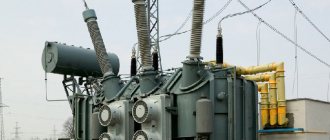
Installation of power transformers
The installation of a power transformer must be carried out by specially trained teams under the guidance of highly qualified electrical personnel. They must have sufficient experience in performing these works in strict accordance with TTM 16.800.723–80. Oil transformers used in power electrical installations can be sent to the manufacturer in the following states:
- Fully filled with oil and assembled;
- Partially disassembled, with a sealed tank in which oil is filled below the cap;
- Partially dismantled without oil, the tank is filled with inert gas;
All work on the installation of transformers is carried out in a clear, regulated sequence
- Unloading electrical equipment after arrival from the manufacturer's factory;
- Transportation to the installation site;
- Preparatory installation work;
- Checking the condition of all windings and switches;
- Installation on a pre-made strong foundation;
- Installation of the cooling system and oil filling, connection of blower fans;
- Inspection for oil leaks;
- Testing of the transformer and trial switching is performed immediately without load during the day.
At the same time, it is better and safer to install transformers during daylight hours.
Application area
These devices are designed to convert the operational parameters of three-phase electrical networks and are used in the following types of power systems:
- electricity transportation and distribution systems;
- converting devices;
- electrical technological installations (welding equipment, electric furnaces, etc.);
- communication and telemechanics devices;
- automation systems;
- household electrical equipment;
- electrical measuring devices.
A suitable connection diagram is determined in accordance with the operating conditions of the device, which include network power, voltage level, and load asymmetry. The choice of connection scheme is also influenced by economic considerations.
Electrical device design
Transformation of three-phase current does not necessarily imply the use of one transformer having a common magnetic circuit. Although such installations are widely used in the national economy.
There is the possibility of such a transformation using three separate single-phase transformers that are not magnetically connected to each other, that is, each individual phase will have its own separate magnetic circuit.
A transformer made according to this scheme is called a group transformer. The primary and secondary windings of the device are interfaced with each other according to one of the schemes adopted for transforming three-phase current.
Structurally, a three-phase transformer is a three-rod magnetic circuit with windings located on each of the rods, made in the same way as for single-phase devices.
Let's imagine three single-phase transformers placed next to each other so that their three rods form one common central rod. On each of the other three rods there are primary and secondary windings.
The currents in the transformer coils will create time-varying magnetic fluxes, which will each be closed in its own magnetic circuit. In the central composite rod, the magnetic fluxes will add up and give a total of zero, because these fluxes are created by symmetrical three-phase currents, regarding which we know that the sum of their instantaneous values is equal to zero at any moment of time.
Let us assume that the primary coils of all transformer bars are exactly the same and wound in the same direction. We connect all the upper ends of the coils to neutral O, and connect the lower ends of the coils to the three terminals of the three-phase network. The magnetic cores are made of sheet electrical steel. To weaken eddy currents and reduce magnetization reversal losses, steel sheets are insulated with varnish before assembly.
Detailed design of a three-phase transformer.
Erroneous designations
Erroneous connections occur when the rules for connecting the ends are not followed. This occurs as a result of incorrect winding or incorrect designation. As a result, when the device is connected to a three-phase network, the windings connected in opposite directions compensate each other’s magnetic fluxes, so a current begins to flow through them, limited only by the active resistance of the winding wire, which is equivalent to a short circuit.
To eliminate cases of incorrect switching, it is recommended that after repairing equipment or before switching on unknown devices, carefully check the phasing of each winding using several methods to eliminate possible errors.
A preliminary calculation of voltages for measurements using the voltmeter method will help reduce the likelihood of error. The data obtained serve as guide values that need to be taken into account when making subsequent measurements.
How to install a current transformer
According to the type and method of installation, they are divided into:
- Passage;
- Support;
- Built into electrical equipment;
- For electrical installations up to 1 kV or higher;
- For outdoor installation in outdoor switchgear (open switchgear);
- For indoor installation in closed switchgear (closed switchgear).
Often, in circuits with low-power motors and transformers designed for 1 kV and below, the installation of a current transformer is not required. These are all kinds of step-down lighting transformers, compressors, fans, heating systems. In general, current transformers are installed extremely rarely in everyday life, except on transformers that supply entire areas or groups of houses.
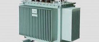
Ready-made solutions - nuclear fuel technology boxes
YaTP is a step-down transformer immediately ready for connection, a module. No need to deal with pins, inputs, windings. The product has appropriately marked sockets for the required load, 36V or otherwise. It is enough to plug its cable into a 220 V network and connect it to the socket on the consumer’s body.
Nuclear fuel transformers can produce any low voltage - 24, 36, 42 V. They are often used for temporary repair work. There are models that allow you to adjust the output voltage.