Owners of private houses often connect a three-phase network to their homes. This option is possible due to various circumstances, but requires convincing justification for implementation. And since power lines (power lines) transmit different current strengths, it will be useful for the owner to know how much voltage actually flows into his house. Let's look at how the power of a three-phase network is calculated. We will also learn how to measure it correctly using instruments.
Three-phase circuit breakers Source pbs.twimg.com
Features of a three-phase system
To equip residential buildings and apartments with electricity, two types of circuits are used:
- single-phase;
- three-phase.
The electrical network from power plants comes out with 3 phases, reaches houses in the same form, and then branches into separate phases.
This method of transmitting electricity is considered economical because it reduces losses during transportation.
Using 3 phases
If you live in an apartment building, then 3 phases are already connected to it, which, in order to optimally distribute the loads, are separated into individual apartments. On each floor there are distribution boards, from where you can bring the missing two phases into the apartment. But this will require permission.
If you wish, you can obtain permission from the energy supply company or coordinate with Energonadzor the installation of three-phase power in your apartment. In this case, you will need to install a three-phase electricity meter.
How to find out your pattern
It’s easy to find out the number of phases in your house or apartment; to do this, you need to open the distribution panel and count the wires through which current enters the apartment.
With a single-phase network, the number of wires will be 2: phase, zero.
Sometimes there is a 3rd ground wire. In a three-phase wiring system there are 4: 3 phases, zero. A ground wire can also be added.
2 popular ways to connect a three-phase system:
- triangle;
- star.
Scheme “Triangle”
Each phase is connected to its neighbors. The current strength from the source is phase, between each other it is linear.
“Star” scheme
The phases are connected at one point. At this point, the total voltage will be 0. The current strength is only phase, and the voltage can vary from linear to phase. What does this give the user? Line voltage in the apartment is 380 V, and phase voltage is 220 V.
Most appliances operate at 220 V, but some appliances require more voltage: old electric stoves, powerful heaters and boilers, industrial power tools.
Thanks to this scheme, any device will work without problems.
What is the current strength of a three-phase network
In practice, the power of an electrical appliance is often a known quantity. Since in most cases a voltage of 220 V is used for power supply, all the necessary data is available to calculate the current strength. This value is important to compare it with the maximum permissible for the wires, sockets and extension cords used.
Important! Excessive current may blow fuses or damage the extension cord you are using. Three-phase system with neutral
Three-phase system with neutral
To determine the current strength, you can use the power formula: P = sq. root(3) * U(l) * I(l) * cos(“phi”).
Here you can use known data:
- P is the power of the electrical appliance, known from its operating instructions;
- U(l). In most cases, we are talking about a voltage of 220 V (for devices with three-phase power supply, this value will be equal to 380 V).
The meaning and formula for cos (“phi”) are usually not known exactly. They are taken from the technical data sheet of the device or refer to reference books for this information. As a rule, for certain types of devices this value is known. For example, it is close to 1 for heating devices, and for electric motors it is 0.7-0.9.
Thus, based on the above formula, the current strength can be calculated based on known data.
Device for measuring power - wattmeter
Properties of a three-phase circuit
A three-phase network has a number of advantages:
- reduces losses when transporting electricity over long distances;
- cables and equipment have lower consumption than that of a monophase network;
- the energy system is balanced;
- In the system there are 2 forms of voltage for operation: linear 380 V and phase 220 V.
Disadvantages of three-phase power
Three-phase power also has several unpleasant aspects that should be considered before connecting:
- Connection and equipment costs
It will be interesting➡ What is a surge protector, what is it for and where is it used?
If you already have a single-phase input into your house, then reconnecting to a three-phase one will require additional expenses. Such expenses include:
- Registration of the contract. According to current legislation, drawing up an agreement for the installation of a three-phase input and a meter costs 550 rubles.
- Purchase of a meter and wires. The average cost of a three-phase meter included in the state register is 1,500 rubles. Also, for input you will need approximately 20 m of insulated SIP cable with a cross-section of 16 mm2, costing 1,200 rubles. It is also worth considering the need to organize wiring inside the house for a three-phase house. This indicator is difficult to calculate, since all houses are different in size.
- Additional machines. Each phase will require its own machine. You will also need to install a voltage monitoring relay so that you can always “monitor” the voltage in each phase and, in case of distortions, switch between phases.
In order for electricians to connect you to a three-phase network, you will have to stand in line and wait a couple of weeks. If you don’t want to wait, you will have to pay separately for urgency. As a result, connecting three-phase power will cost its owner a tidy sum.
- Increased dimensions of the panel room
To connect three-phase power it is necessary to install a large switchboard. This is due to the presence of additional protective and distribution equipment. Typically, such a power cabinet or switchboard is installed outdoors so that it does not take up much space in the house.
It is worth noting that energy sales have certain requirements for distribution boards. For example, protection of the switchboard from dust and dirt should be at least IP31, and in wet rooms IP54. For some owners of summer cottages or private houses, finding a suitable place for a cabinet or installing such a structure can be a real challenge.
- Re-wiring in the house
If initially the house had one phase, then connecting two more will require the owner to completely redesign the wiring. So initially all sockets and light bulbs were “planted” on one phase. With a three-phase connection, these sockets will need to be moved, and this means considerable repairs in the house, since you will have to trench the walls for the wiring. Naturally, this work requires additional time and money.
Three-phase or single-phase connection
Depending on what type of connection is used, the power consumption is determined differently.
In a single-phase network, the energy consumed is calculated using the simplest formula:
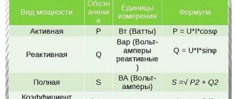
where cosϕ is the power factor characterizing the phase shift between current and voltage in a reactive load.
The power of a 3-phase network is the sum of consumption for each phase separately. The power formula for 3-phase current is as follows:
Ptotal=Uа∙Iа∙cosϕа+ Ub∙Ib∙cosϕb+ Uc∙Ic∙cosϕc,
where U, I, cosϕ are voltage, current and power factor in each phase, respectively.
For your information. It can be seen that in the general case, a three-phase connection requires a larger number of metering devices.
Sometimes you can calculate energy consumption using a simplified version. With symmetrical consumption, for example, when connecting an asynchronous motor, the consumption currents are the same, and the formula takes the following form:
Where:
- Uph, Iph – phase voltage and current;
- Ul, Il – linear voltage and current.
Features of connecting power to a private home
Many people believe that a three-phase network in the house increases power consumption. In fact, the limit is set by the electricity supply organization and is determined by the following factors:
- supplier capabilities;
- number of consumers;
- condition of the line and equipment.
To prevent voltage surges and phase imbalance, they should be loaded evenly. The calculation of a three-phase system is approximate, since it is impossible to accurately determine which devices will be connected at a given moment. The presence of pulsed devices currently leads to increased energy consumption during their startup.
The electrical distribution panel for a three-phase connection is larger in size than for a single-phase supply. Options are possible with the installation of a small input panel, and the rest made of plastic for each phase and for outbuildings.
Connection to the main line is carried out using underground and overhead lines. Preference is given to the latter due to the small amount of work, low connection cost and ease of repair.
Nowadays it is convenient to make an air connection using a self-supporting insulated wire (SIP). The minimum cross-section of an aluminum core is 16 mm2, which is sufficient for a private home.
The SIP is attached to the supports and the wall of the house using anchor brackets with clamps. The connection to the main overhead line and the input cable to the electrical panel of the house is made with branch piercing clamps. The cable is taken with non-combustible insulation (VVGng) and passed through a metal pipe inserted into the wall.
We advise you to study - What is dialing and how to correctly dial wires, cables and various electrical equipment
Characteristics of a three-phase system
A three-phase power supply system is characterized by several voltage and current values. It all depends on between which points of the circuit the measurements are made:
- between the phase wire and the neutral – phase voltage Uph;
- between individual phases – linear Ul.
The relationship between these parameters:
With symmetrical load distribution, the currents in all wires are equal. In a four-wire circuit (with a grounded zero), there is no current in the neutral conductor, so even if the zero is broken, the network continues to function normally.
In the case where the energy consumption differs between phases, some current flows in the neutral wire. A complete break in the neutral conductor causes a phase imbalance, so the voltage on the wires can change in the range from zero to linear.
The reactive nature of the load is taken into account by the power factor cosϕ. This value comes from the theory of complex numbers, which are used when it is necessary to calculate the parameters of alternating current circuits. In the case of an active load, cosϕ = 1, but the more reactive the consumers are, the more the coefficient decreases, showing how the real power decreases relative to the total.
Important! Therefore, to correctly calculate and reduce the load on generating equipment, power factor correctors are installed in reactive circuits. Circuits with a corrector bring the cosϕ coefficient closer to unity.
What is three-phase current
An electrical circuit with a three-phase system is a connection diagram to which three cable cores are connected. In each there are alternating electromotive forces of the same frequencies, but shifted in phase by one third of the period relative to each other. In the language of physics, the shift looks like alpha = 2*pi/3. Each individual circuit of the entire circuit as a whole is called a phase. And since there are three of them, the whole scheme received the appropriate name.
Operating principle of a three-phase generator
Almost all generators of power plants produce three-phase current. They combine the design of simultaneous initiation of excitation of electromotive forces shifted relative to each other. Its device includes three independent armatures located on the stator of the installation and spaced from each other by one third of the circle. In the center there is an induction element, presented as a permanent magnet.
The figure shows the difference between three-phase current and single-phase current. The diagram shows three coils, which themselves are independent voltage generators. If you connect each of them to a separate network with its own load, then they are able to supply electricity to any devices.
However, continuing the logic of the schematic wiring connection, six cables will be required for the general power supply to the receiving equipment. From a rational point of view, such a chain will be cumbersome and not economical. Therefore, the coils are connected in such a way that only three or four cables are needed. Such a system is called three- and four-wire, one of which is zero, that is, not under current voltage.
Star connection
Calculation
Calculating the power of a three-phase system is difficult, because the current in the network is not constant, but alternating.
With constant current, power is calculated by multiplying voltage and current. With alternating current, all quantities are unstable due to the presence of several phases. The connection method also matters. With a single-phase system, power is also calculated by multiplying voltage and current, but taking into account the power factor-cos, which characterizes the phase shift between voltage and current for a reactive load.
The calculation takes place according to the following formula for the complete calculation of current power in a three-phase network:
Ptotal=Uа∙Iа∙cosа+ Ub∙Ib∙cosb+ Uc∙Ic∙cosc
where U is voltage, I is current, cos is power factor, a, b and c are phases.
Power measurement in three-phase circuits is carried out with a wattmeter.
With a symmetrical load, only one phase is measured and the measurement result is multiplied by 3. When measuring 3 phases at once, 3 devices will be required. In the absence of the “zero” phase, the measurement is carried out by 2 devices and the power calculation is calculated according to Kirchhoff’s 1st law:
Ia+Ib+Ic=0
The sum of the readings of two wattmeters will give an indicator of the power of the three-phase circuit.
What is power Watt [W]
Power is a quantity that determines the ratio of work performed by a current source over a certain period of time. One watt corresponds to one ampere times one volt, but kilowatt/hour is used to determine energy costs.
It corresponds to the consumption of one thousand watts for 60 minutes of operation. It is by this indicator that the cost of electricity services is determined.
In most cases, the power consumed by the device is indicated in the technical documentation or on the packaging. The specified quantity is produced in one hour of work.
To help determine the current strength at a known power, a calculator will help, which converts one physical quantity to another.
How to calculate?
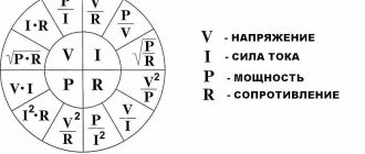
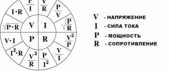
Ohm's law will help determine any quantity related to electrical energy. It states that voltage is equal to current times resistance, and power is force times voltage.
Current voltage is its strength multiplied by its resistance. The indicator is needed to select the optimal wires and cables in the house. It turns out that in order to calculate the current by power, you need to know its strength and voltage. But how to calculate amperes, knowing power and voltage, for example? Again following Ohm's law. To do this, you need to divide the power by the voltage.
To find the power, knowing the current and voltage, you need to multiply the force in amperes by the voltage in volts.
You can make an exact calculation using our calculator.
It is enough to simply find out the current strength; it is much more difficult to calculate the cross-section of the wires. To do this, you need to calculate the current strength and use the following table:
| Cross-section of copper wire depending on the amount of current consumed | ||||||||||||||
| Maximum current in amperes | 1 | 2 | 3 | 4 | 5 | 6 | 10 | 16 | 20 | 25 | 32 | 40 | 50 | 63 |
| Wire cross-section in millimeters | 0,17 | 0,33 | 0,52 | 0,67 | 0,84 | 1 | 1,7 | 2,7 | 3,3 | 4,2 | 5,3 | 6,7 | 8,4 | 10,5 |
In order to calculate the power, knowing the current and voltage, use the table below:
| Electrical equipment | Device power in watts | Power in amperes |
| Washing machine | 2000 | 10 |
| "Warm floor" | 1000 | 5 |
| Kitchen stove | 7000 | 35 |
| Microwave | 1000 | 5 |
| Dishwasher | 2000 | 10 |
| Fridge | 250 | 1 |
| Food processor | 1100 | 5 |
| Kettle | 1900 | 9 |
| Coffee maker | 1100 | 5 |
| Mixer | 300 | 1,4 |
| Hairdryer | 1000 | 2 |
| Iron | 1500 | 6 |
| Vacuum cleaner | 1200 | 5 |
| TV | 150 | 0,7 |
| Radio | 100 | 0,4 |
| Lamps | 50 | 0,2 |
How to measure power of different types
Measurement of different power types occurs according to formulas derived from the end of the last century and the century before last. Each variety has its own exact algebraic rule. So, you can measure the mechanical one using the first formula, and the electrical one using the second. As for the hydraulic one, it can be calculated using the third algebraic rule.
Measuring using formulas
Mechanical
Mechanical power is the scalar form of the product of the force vector and the speed vector at which some object is moving. Based on the formula for calculating this indicator, in order to find it, you need to know the indicator of the force vector with the speed vector, and the last of them is equal to the magnitude of the force multiplied by the magnitude of the velocity and the vector angle of the velocity with the force.
Regarding the calculation of a body that performs rotational movements, it can be noted that you need to have an idea of the indicator of the moment of force with angular velocity.
Additional Information! If this data is unknown in the problem, you can multiply the double number Pi by the rotation speed per minute at the moment of force, and then divide the obtained information by 60. In this way, calculations are made in mechanics if you need to understand what force an engine or other power unit has.
Electric
Electrical power is a quantity that shows the speed or transformation at which electrical energy moves. To study the instantaneous electrical power characteristic in a certain section of the circuit, it is necessary to know the value of the current and voltage of the instantaneous current and multiply these values.
To understand how much the active, total, reactive or instantaneous reactive power indicator is, you need to know the exact numbers of current amplitude, voltage amplitude, angle of current with voltage, as well as angular velocity and time, since all existing physical formulas are reduced to these parameters. The formulas also use the sine, cosine of the angle and the value 1/2.
Electric power concept
Hydraulic
The hydraulic power indicator in a hydraulic machine or hydraulic cylinder is the product of the machine pressure drop and the liquid flow rate. Typically this is the basic formulation taken from the only existing formula for the calculation.
Note! More algebraic and engineering rules can be found in the applied science of the movement of liquids and gases, namely in hydraulics
Direct and alternating current
As for direct and alternating current power, they are most often classified as the electrical variety. There is no specific concept for the two varieties, but they can be calculated based on existing algebraic settings. Thus, direct current power is the product of current and constant voltage, or twice the current and electrical resistance, which, in turn, is calculated by dividing twice the voltage by the usual resistance.
As for alternating current, this is the product of the current strength with the voltage and the cosine of the phase shift. In this case, only the active and reactive varieties can be easily counted. You can find out the full power value through the vector dependence of these indicators and area.
To measure these indicators, you can use both the above instruments and a phase meter. This device is used to calculate the reactive variety according to the state standard.
Concept of variable current power
In general, power is a quantity whose main purpose is to show the strength of a particular device and, in many cases, the speed of activity interacting with it. It can be mechanical, electrical, hydraulic and for direct current and alternating current. Measured according to the international system in watts and kilowatts. The instruments for calculating it are a voltmeter and a wattmeter. The basic formulas for independent calculations are listed above.
Measuring power with a wattmeter
The power consumption of three-phase current is measured using wattmeters. This can be a special wattmeter for a 3-phase network, or a single-phase one connected according to a specific circuit. Modern electricity metering devices are often made using digital circuitry. Such designs are characterized by high measurement accuracy and greater capabilities for operating with input and output data.
Measurement options:
- Star connection with neutral conductor and symmetrical load - the measuring device is connected to one of the lines, the readings taken are multiplied by three.
- Asymmetrical current consumption in a star connection - three wattmeters in the circuit of each phase. The wattmeter readings are summed up;
- Any load and delta connection - two wattmeters connected in a circuit of any two loads. The wattmeter readings are also summed up.
In practice, they always try to make the load symmetrical. This, firstly, improves network parameters, and secondly, simplifies the accounting of electrical energy.
How to find out what power is in an AC circuit
It is worth pointing out that this is a value that is directly related to other indicators. For example, it is directly dependent on time, force, speed, vector of force and speed, modulus of force and speed, moment of force and speed of rotation. Often in formulas when calculating electrical power, the number Pi is also used with the resistance indicator, instantaneous current, voltage in a specific section of the electrical network, active, total and reactive power. Direct participants in the calculation are the amplitude, angular velocity and initial current strength with voltage.
In a single-phase circuit
You can understand what power indicator is in a single-phase alternating current circuit by using a current transformer. To do this, you need to use a wattmeter, which is connected through a current transformer. The readings should be multiplied by the transformer current coefficient. When measuring power at high voltage, a current transformer is needed to insulate the wattmeter and ensure the safety of the user. The parallel circuit is not connected directly, but thanks to a voltage transformer. Secondary windings with housings of measuring transformer installations must be grounded to avoid accidental insulation damage and high voltage contact with devices.
Note! To determine the parameters in the network, it is necessary to multiply the ammeter by the transformer current coefficient, and multiply the numbers obtained by the voltmeter by the transformer voltage coefficient
In a three-phase circuit
In an alternating current circuit, the power indicator in a three-phase circuit can be determined by multiplying the current by the voltage. Since this is not a constant electric current, it depends on time and other parameters, so it is necessary to use other proven circuits. So, you can use a wattmeter.
The measurement must be carried out in only one phase and multiplied by three according to the formula. This method saves equipment and reduces measurement dimensions. Used for high precision measurement of each phase. In case of an asymmetrical load, you need to use the appropriate wattmeter connection diagram. This is a more accurate method, but requires three wattmeters.
Note! If the circuit does not provide for the presence of a neutral conductor, an appropriate circuit is also needed. It is worth pointing out that today you can measure the necessary indicators not only with an analogue, but also with a digital device
The difference between the second one is its reduced size and lightness. In addition, digital units have ways to record current with voltage, network cosine, and others. This makes it possible to monitor various quantities from a distance and transmit warnings if there is a deviation. This is convenient because you don’t need to measure current with voltage, and then, using formulas, calculate everything thoroughly
It is worth pointing out that today it is possible to measure the necessary indicators not only with an analogue, but also with a digital device. The difference between the second one is its reduced size and lightness. In addition, digital units have ways to record current with voltage, network cosine, and others. This makes it possible to monitor various quantities from a distance and transmit warnings if there is a deviation. This is convenient because you don’t need to measure current with voltage, and then, using formulas, calculate everything thoroughly.
In general, power is a quantity whose main purpose is to show the strength of a particular device and, in many cases, the speed of activity interacting with it. It can be mechanical, electrical, hydraulic and for direct current and alternating current. Measured according to the international system in watts and kilowatts.
In order to ensure safety when operating industrial and household electrical appliances, it is necessary to correctly calculate the cross-section of the supply wiring and cable. An incorrect choice of cable cross-section can lead to a short circuit causing fire in the wiring and causing a fire in the building.
Formulas for DC circuit calculations
The easiest way to calculate the power is for a DC circuit. If there is current and voltage, then you just need to perform the calculation using the formula given above:
P=UI
But it is not always possible to find power by current and voltage. If you don't know them, you can determine P by knowing the resistance and voltage:
P=U2/R
You can also perform the calculation knowing the current and resistance:
P=I 2 *R
The last two formulas are convenient for calculating the power of a section of a circuit if you know the R of the element I or U that falls on it.
Equipment for network short circuit protection
You already know how to calculate amps when you know the power and voltage, or calculate power when you know the current and voltage. But sometimes even accurate and correct calculations do not save you from a short circuit. An emergency can happen on a three-phase line for reasons beyond the control of the user: a foreign object hitting the wires, a break due to a falling tree. In this case, even if you have calculated the current strength as correctly as possible and your house has the most ideal wiring, a fire or failure of electrical appliances is possible. You can protect your network in the following ways:
- install a fuse. If the amperes in the electrical circuit exceed the permissible values, the fuse will melt and the circuit will be broken. The price of a fuse is 400-600 rubles. Choose a domestically produced product designed to work with our electrical networks;
- install a circuit breaker. This is modern equipment that reliably protects household appliances from premature failure due to problems with wires. Costs from 200 to 2 thousand rubles. It will blow in seconds, unlike a fuse, which will take about half a minute to open. When connecting, study detailed information about wire markings.
An automatic current switch will protect household appliances from damage due to a short circuit.
What is rated power?
This definition refers to an established indicator that allows you to connect a certain number of pieces of equipment at the same time. If you exceed their permissible number, the automatic protective system may fail. The calculation of installed power is carried out by summing this indicator, which characterizes each connected device in the system.
Important! The interfloor space of a residential building is equipped with an electrical panel and an input device, from which cables are laid to each apartment. In the case when the system is located in a residential area, a cable with the required cross-section is laid in it
To protect the distribution lines, an automatic machine, a counting device and a shield are installed to evenly distribute the loads on each line.
Electrical panel
Example of calculating total power for an electric motor
The power of electric motors can be useful or mechanical on the shaft and electrical. They differ by the coefficient of performance (efficiency), this information is usually indicated on the nameplate of the electric motor.
From here we take the data to calculate the connection in a triangle to Ulinear 380 Volts:
Then you can find the active electrical power using the formula:
P=Pon the shaft/n=160000/0.94=170213 W
Now we can find S:
It is this that needs to be found and taken into account when selecting a cable or transformer for an electric motor. This completes the calculations.
Selecting the rating of the circuit breaker
Applying the formula I = P/209, we find that with a load with a power of 1 kW, the current in a single-phase network will be 4.78 A. The voltage in our networks is not always exactly 220 V, so it would not be a big mistake to calculate the current strength with a small margin like 5 A for every kilowatt of load. It is immediately clear that it is not recommended to connect an iron with a power of 1.5 kW to an extension cord marked “5 A”, since the current will be one and a half times higher than the rated value. You can also immediately “graduate” the standard ratings of the machines and determine what load they are designed for:
- 6 A – 1.2 kW;
- 8 A – 1.6 kW;
- 10 A – 2 kW;
- 16 A – 3.2 kW;
- 20 A – 4 kW;
- 25 A – 5 kW;
- 32 A – 6.4 kW;
- 40 A – 8 kW;
- 50 A – 10 kW;
- 63 A – 12.6 kW;
- 80 A – 16 kW;
- 100 A – 20 kW.
Using the “5 amperes per kilowatt” technique, you can estimate the current strength that appears in the network when connecting household devices. You are interested in peak loads on the network, so for the calculation you should use the maximum power consumption, not the average. This information is contained in the product documentation. It is hardly worth calculating this indicator yourself by summing up the rated powers of the compressors, electric motors and heating elements included in the device, since there is also such an indicator as the efficiency factor, which will have to be assessed speculatively with the risk of making a big mistake.
When designing electrical wiring in an apartment or country house, the composition and passport data of the electrical equipment that will be connected are not always known for certain, but you can use the approximate data of electrical appliances common in our everyday life:
- electric sauna (12 kW) - 60 A;
- electric stove (10 kW) - 50 A;
- hob (8 kW) - 40 A;
- instantaneous electric water heater (6 kW) - 30 A;
- dishwasher (2.5 kW) - 12.5 A;
- washing machine (2.5 kW) - 12.5 A;
- Jacuzzi (2.5 kW) - 12.5 A;
- air conditioner (2.4 kW) - 12 A;
- Microwave oven (2.2 kW) - 11 A;
- storage electric water heater (2 kW) - 10 A;
- electric kettle (1.8 kW) - 9 A;
- iron (1.6 kW) - 8 A;
- solarium (1.5 kW) - 7.5 A;
- vacuum cleaner (1.4 kW) - 7 A;
- meat grinder (1.1 kW) - 5.5 A;
- toaster (1 kW) - 5 A;
- coffee maker (1 kW) - 5 A;
- hair dryer (1 kW) - 5 A;
- desktop computer (0.5 kW) - 2.5 A;
- refrigerator (0.4 kW) - 2 A.
The power consumption of lighting devices and consumer electronics is small; in general, the total power of lighting devices can be estimated at 1.5 kW and a 10 A circuit breaker is sufficient for a lighting group. Consumer electronics are connected to the same outlets as irons; it is not practical to reserve additional power for them.
If you sum up all these currents, the figure turns out to be impressive. In practice, the possibility of connecting the load is limited by the amount of allocated electrical power; for apartments with an electric stove in modern houses it is 10 -12 kW and at the apartment input there is a machine with a nominal value of 50 A. And these 12 kW must be distributed, taking into account the fact that the most powerful consumers concentrated in the kitchen and bathroom. Wiring will cause less cause for concern if it is divided into a sufficient number of groups, each with its own machine.
For the electric stove (hob), a separate input with a 40 A automatic circuit breaker is made and a power outlet with a rated current of 40 A is installed; nothing else needs to be connected there. A separate group is made for the washing machine and other bathroom equipment, with a machine of the appropriate rating. This group is usually protected by an RCD with a rated current 15% greater than the rating of the circuit breaker. Separate groups are allocated for lighting and for wall sockets in each room.
You will have to spend some time calculating powers and currents, but you can be sure that the work will not be in vain. Well-designed and high-quality electrical wiring is the key to the comfort and safety of your home.
Three-phase power: advantages
The presence of three phases brings a lot of advantages to the owner of a private house or cottage. Here are some of them:
- Increased capacity
Every year the number of household electrical appliances in each home increases, which means their total power and the load they transfer to the electrical grid increase. Today in Russia, local Oblenergos offer the opportunity to draw up a contract for the consumption of 5 kW for single-phase networks and 15 kW for three-phase networks.
Let's assume you have one phase and the total power of all electrical appliances in your house is 4 kW. But time passed, and you decided to buy yourself a 3 kW welding machine. By the way, you can read about which welding machine to buy here. In this case, the total power will be 7 kW, and you will not be able to use all devices at the same time. And if in the future you plan to install pumping equipment or an electric heating system, then you should think about connecting a three-phase network.
- Even load distribution
Thanks to the operation of three phases simultaneously, it is possible to evenly distribute the load between them to avoid distortion. For example, if you regularly weld in the garage, it is best to do it on a different phase to which the TV, computer equipment or light bulbs in the house are connected. You can calculate the load for each household appliance and distribute them proportionally across phases.
There are also cases when, due to increased load (not through your fault), the voltage drops to 170 V or even lower on certain phases. This often happens if the house is located at a great distance from the transformer substation, and there are dozens of other consumers in front of it. In this case, the equipment can be temporarily switched to a less loaded phase, and when the imbalance “goes away”, everything can be returned to its place.
- Operation of three-phase equipment
Although most household appliances operate on 220 V, there is still equipment for three-phase networks of 380 V. The following types of such equipment can be distinguished:
- Pumping stations. Some deep and surface pumping stations require 380 V.
- Transformer welding machines.
- Heating boilers. Most electric heating boilers have a rated power of 7 - 9 kW - a single-phase network simply would not cope with it. For example, for a single-circuit boiler EVAN Warmos-IV-9.45 with a power of 9.45 kW, three phases are required.
- Possibility of installing automatic circuit breakers and RCDs with lower nominal values
Due to the fact that each phase wire in a three-phase network will have a lower load than on one phase in the case of a single-phase input, it is possible to install circuit breakers and RCDs with lower current loads. For example, if devices with a total power of 3 kW are placed on each phase, then each phase will require an automatic machine capable of withstanding such a load:
3000/220 = 13.6 A (phase load)
The closest machine is rated at 16 A. For single-phase power supply with a maximum possible power of 5 kW, you will need a more powerful machine. The same rule applies to residual current devices. We have already written about how to choose an RCD based on power, so we will not dwell on this.
Calculation of Power by Current and Voltage
To protect yourself when working with household electrical appliances, you must first correctly calculate the cross-section of the cable and wiring. Because if the cable is chosen incorrectly, it can lead to a short circuit, which can lead to a fire in the building, the consequences can be catastrophic.
This rule also applies to the choice of cable for electric motors.
Why is it necessary to check the phase voltage before turning it on?
When connecting equipment that requires a voltage of 380 V (for example, an asynchronous electric motor), you should check the voltage on each of the three phases and compare the indicators. This is especially true in private sectors where the voltage is unstable or electricians are insufficiently qualified. The fact is that in villages they often do not pay attention to load distribution. As a result of such actions, one of the phases may be overloaded with minimal load on the others. Coupled with outdated transformers, this leads to phase imbalance. It turns out that in one of the phases the voltage decreases significantly. This leads to overheating of three-phase motors or other equipment and its failure.
Calculation of power by current and voltage
This calculation occurs based on the actual power; it must be done before you start designing your home (house, apartment).
- This value determines the cables that power the devices that are connected to the electrical network.
- Using the formula, you can calculate the current strength; for this you need to take the exact network voltage and the load of the powered devices. Its size gives us an idea of the cross-sectional area of the veins.
If you know all the electrical appliances that should be powered from the network in the future, then you can easily make calculations for the power supply diagram. The same calculations can be performed for production purposes.
Single-phase 220 volt network
Current formula I (A - amperes):
Where P is the electrical full load (its designation must be indicated in the technical data sheet of this device), W - watt;
U—mains voltage, V (volts).
The table shows the standard loads of electrical appliances and the current they consume (220 V).
| electrical appliance | Power consumption, W | Current strength, A |
| Washing machine | 2000 – 2500 | 9,0 – 11,4 |
| Jacuzzi | 2000 – 2500 | 9,0 – 11,4 |
| Electric floor heating | 800 – 1400 | 3,6 – 6,4 |
| Stationary electric stove | 4500 – 8500 | 20,5 – 38,6 |
| microwave | 900 – 1300 | 4,1 – 5,9 |
| Dishwasher | 2000 — 2500 | 9,0 – 11,4 |
| Freezers, refrigerators | 140 — 300 | 0,6 – 1,4 |
| Electric meat grinder | 1100 — 1200 | 5,0 — 5,5 |
| Electric kettle | 1850 – 2000 | 8,4 – 9,0 |
| Electric coffee maker | 6з0 — 1200 | 3,0 – 5,5 |
| Juicer | 240 — 360 | 1,1 – 1,6 |
| Toaster | 640 — 1100 | 2,9 — 5,0 |
| Mixer | 250 — 400 | 1,1 – 1,8 |
| Hairdryer | 400 — 1600 | 1,8 – 7,3 |
| Iron | 900 — 1700 | 4,1 – 7,7 |
| Vacuum cleaner | 680 — 1400 | 3,1 – 6,4 |
| Fan | 250 — 400 | 1,0 – 1,8 |
| TV | 125 — 180 | 0,6 – 0,8 |
| Radio equipment | 70 — 100 | 0,3 – 0,5 |
| Lighting devices | 20 — 100 | 0,1 – 0,4 |
In the figure you can see a diagram of the power supply device at home with a single-phase connection to a 220 volt network.
Device diagram for single-phase voltage
As shown in the figure, all consumers must be connected to the appropriate machines and meter, then to a general machine that will withstand the total load of the house. The cable that will carry the current must withstand the load of all connected household appliances.
The table below shows hidden wiring for a single-phase housing connection to select a cable at a voltage of 220 volts.
| Wire core cross-section, mm 2 | Conductor core diameter, mm | Copper conductors | Aluminum conductors | ||
| Current, A | Power, W | Current, A | power, kWt | ||
| 0,50 | 0,80 | 6 | 1300 | ||
| 0,75 | 0,98 | 10 | 2200 | ||
| 1,00 | 1,13 | 14 | 3100 | ||
| 1,50 | 1,38 | 15 | 3300 | 10 | 2200 |
| 2,00 | 1,60 | 19 | 4200 | 14 | 3100 |
| 2,50 | 1,78 | 21 | 4600 | 16 | 3500 |
| 4,00 | 2,26 | 27 | 5900 | 21 | 4600 |
| 6,00 | 2,76 | 34 | 7500 | 26 | 5700 |
| 10,00 | 3,57 | 50 | 11000 | 38 | 8400 |
| 16,00 | 4,51 | 80 | 17600 | 55 | 12100 |
| 25,00 | 5,64 | 100 | 22000 | 65 | 14300 |
As shown in the table, the cross-section of the cores also depends on the material from which it is made.
Experience in operating AFG in existing electrical installations
Laboratory tests of AFG-25 and AFG-100 with a nonlinear load power commensurate with the installed filter power confirmed the possibility of stable operation of the developed products in electrical installations with a variable nonlinear load such as an uncontrolled rectifier of varying pulse rates. It was possible to achieve a significant improvement in the sinusoidality of the consumed current and the voltage curve at the point of connection of the AFG (see Figure 4).
After turning on the AFG in operation (the appearance of a compensation current signal), the shape of the current curve on the side of the electricity source became almost sinusoidal while the significantly non-sinusoidal load current curve remained unchanged.
Some results of tests performed on the functioning of the AFG are given below.
The readings of the PKE devices during tests before and after turning on the AFG in operation are shown in the table, in Figure 5 a, b. The results show the dominant harmonics. PKE meter readings during AFG tests
| I1, A | I5, % | I7, % | I11, % | I13, % | I19, % | THD I, % | |
| Comprehensive compensation for HCV Idc= 70A | |||||||
| with AFG | 25,8 | 1,0 | 1,1 | 0,9 | <1 | 3,6 | |
| without AFG | 24,9 | 21,5 | 9,6 | 7,7 | 4,9 | 2,4 | 25,9 |
| Selective compensation of 5th, 7th, 11th harmonics Idc= 70A | |||||||
| with AFG | 26,4 | 1,4 | 1,2 | 1,1 | 4,3 | 2,4 | 8,2 |
| Selective compensation of 5th, 13th harmonics Idc= 70A | |||||||
| with AFG | 26,3 | 1,4 | 9,9 | 7,3 | 0,9 | 2,4 | 11,1 |
where THDI - Current harmonic distortion factor
Idc - current consumed by the load from the controlled rectifier
I1— fundamental harmonic current
IN is the harmonic current, where N is the order of the harmonic
Trial operation of the AFG as part of the electrical installation of shop No. 3 of OJSC "CS "Zvezdochka" showed stable operation of the product in the mode of compensation of higher harmonic components of the current during the full cycle of metal melting with an induction furnace, the parameters of the oscillatory circuit of which were controlled using a thyristor frequency converter type TPChP-400- 1.0.
During the operation of the AFG, a significant reduction in the negative impact of the operating 400 kW induction furnace complex on the source of the industrial frequency power supply system (step-down transformers RTP-132x1000 kVA 10/0.4 kV) was ensured. The overall coefficient of current waveform distortion (Kgt) during furnace operation decreased by 40% (without AFG Kgt = 27.74%, when AFG was operating in the VGS compensation mode Kgt = 16.9%)
