The Object-Micrometer is designed for calibrating visualization and measurement systems of digital microscopes, which provides measurement of the linear dimensions of objects and performing other calculations based on the measurement and processing of linear dimensions in the field of view of the microscope in transmitted light, dark field, phase contrast, luminescence, polarization, etc. reflected light and other types of microscope studies.
In digital microscopes, the Object-Micrometer is used to calibrate the digital imaging system of the microscope for subsequent automatic measurement of distances. The microscope digital imaging system consists of Software (hereinafter referred to as Software) and a digital camera. In order for the software to be able to measure and analyze images, it is necessary to determine the coefficient
recalculation of the size of a micro-object, measured in conventional units “Pixel” (digital camera resolution) into the dimensions of the metric SI system “Micrometers” (or nm, mm).
By taking an image of the Object-Micrometer scale at each working magnification of the microscope and specifying a known distance in the calibration mode, you set the conversion factor to real units of length in the international SI system (meter, millimeter, micrometer, nanometer, etc.).
Also, the Object-Micrometer is used to determine the magnification and linear field of view of microscopes, microprojectors, as well as the division value of the eyepiece-micrometer, ocular scales and reticles.
Glass plate 75 x 25 x 1 mm
Scale length - 1 mm in a circle with a diameter of 5 mm
Scale division value - 0.01 mm
Number of divisions in the scale – 100 pcs.
Thickness of marks - about 0.003 mm
The Micrometer Object is marked 1 DIV = 0.01mm
The Micrometer object is a glass plate 75 mm x 25 x 1 mm, which corresponds to the standard dimensions of a glass slide used in microscopy. A 1 mm long ruler is engraved in the center of the glass, divided into 100 parts. Therefore, the reading of one division corresponds to 0.01 mm, which is equal to 10 µm.
The Object-Micrometer is supplied in a standard plastic case, which allows you to protect the glass of the Object-Micrometer from damage during transportation and storage.
The circle around the scale itself allows you to conveniently and quickly find the Object-Micrometer scale in the eyepieces of a microscope or in the field of view of a microscope with a digital imaging system when displaying an image on a computer monitor.
It should be remembered that for calibration at 100X magnification it is necessary to use immersion oil (for oil lenses).
Protect the Micrometer object from shock loads and bending and store it in a standard plastic case. When cleaning the Object-Micrometer from residues of biomaterial and immersion oil, avoid the use of abrasive cleaning agents.
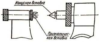
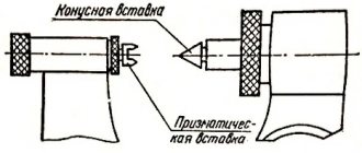
Determination of instrument readings
The pointer when counting on scale 2 of the stem is the end of the drum, and the longitudinal stroke 1 is the pointer for the circular scale 3. The numbered scale of the stem shows the number of millimeters, and its additional scale serves to count half millimeters.
Let us mark the last stroke of the millimeter scale of the stem, completely opened by the drum. Its value is an integer number of millimeters and is indicated in green in the figure. If there is an open line of an additional scale to the right of this stroke (highlighted in blue), you need to add 0.5 mm to the resulting value.
When reading the readings of the circular scale 3, take into account its value that coincides with the longitudinal stroke 1. Thus, in the upper image, the readings of the device are:
- 16 + 0.22 = 16.22 mm.
- 17 + 0.5 + 0.25 = 17.75 mm.
A common mistake is when the value of 0.5 mm is incorrectly taken into account (or not taken into account). This is due to the fact that the stroke of the additional scale closest to the drum may be partially open. If necessary, check yourself with a caliper.
Option 1. Application in an optical system
- Remove the Micrometer Object from the case. Make sure the glass is clean and clean it if necessary;
- Place the Object-Micrometer on the microscope stage, with the side on which the scale is applied facing the sample of light-transmitting biological or histological material.
- Using a 4x lens, use the microscope adjustments to focus on the biological object and center the Object-Micrometer scale in the field of view by moving the object table.
- Switch to the lens required for measuring the biological specimen, adjust the focal length and adjust the position of the stage using the microscope adjustments;
- Make a measurement of the cell sizes of a biological or histological specimen, combined with the Object-Micrometer scale for a microscope.
The procedure for taking measurements with a micrometer
The working surfaces of the micrometer are set apart by an amount slightly larger than the size of the part being measured, otherwise it can be scratched during operation.
The fact is that the end surfaces of the heel and micrometer screw have high hardness for abrasion resistance. The heel is lightly pressed against the part and the micrometer screw is rotated using a ratchet until it comes into contact with the surface being measured. The ratchet is used to regulate the tension force - usually 3-5 clicks are made. The position of the micrometer screw is fixed using a locking device in order not to disrupt the readings when reading values from the scale.
When working with a micrometer, it should be held by the bracket so that the stem scale is visible and readings can be taken on the spot.
When measuring the diameter of a shaft, the measuring surfaces must be placed at diametrically opposite points. In this case, the heel is pressed against the shaft, and the micrometer screw, which is slowly rotated with a ratchet, is sequentially aligned in two directions: axial and radial. After work, you need to check the accuracy of the tool using a standard.
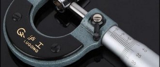
Micrometer
A micrometer allows you to increase the accuracy of measurements compared to a caliper by an order of magnitude, i.e. another 10 times. There are several types of micrometers: for external measurements, micrometric depth gauge and micrometric internal gauge.
A micrometer for external measurements is shown in Fig. I.4 .
To measure, an object is placed between a fixed stop
1
and the movable end of a micrometer screw
2
.
The micrometer screw, rigidly connected to the drum 3
, moves inside the hollow fixed cylinder
4
. The micrometer screw has a pitch of 0.5 mm.
The micrometer reading device consists of two scales - horizontal and circular. The horizontal scale, located on a stationary cylinder along which the drum moves, has a division value of 0.5 mm. It is a double scale marked on both sides of the longitudinal line in such a way that the upper scale is shifted relative to the lower one by 0.5 mm. Consequently, when the micrometer screw makes a full revolution, the drum moves from the upper division to the lower. The division value of the circular scale located on the conical part of the drum is 0.01 mm. Indeed, the number of divisions on the drum is n
=50. This means that when rotated by 50 divisions, the drum moves by 0.5 mm, and when rotated by one division, by 0.01 mm.
The counting is carried out as follows: the size of the measured object is measured on the horizontal scale of the cylinder with an accuracy of 0.5 mm. Hundredths of a millimeter are counted on the drum's circular scale. Moreover, the number of hundredths corresponds to the scale division located opposite the longitudinal line of the cylinder. The results obtained are added up.
Attention! The micrometer screw must be rotated only by the ratchet 5
until a characteristic sound appears. This prevents damage to the device.
Device of a smooth micrometer type MK-25
The main design elements of a smooth micrometer are presented in the figure below and indicated by numbers:
- Brace. It must be rigid, since its slightest deformation leads to a corresponding measurement error.
- Heel. It can be pressed into the body, or it can be replaceable for micrometers with a large measurement range (500 - 600 mm, 700 - 800 mm, etc.).
- Micrometric screw that moves when the ratchet rotates 7.
- Stopping device. For the micrometer in the figure, it is made in the form of a screw clamp. Used to secure the micrometer screw when setting the instrument or taking readings.
- Stem. There are two scales on it: the numbered (main) scale shows the number of whole millimeters, the additional one shows the number of half millimeters.
- A drum on which tenths and hundredths of a millimeter are counted. The end of the drum is also an indicator for the stem scale 5.
- Ratchet for rotating the micrometer screw 3 and adjusting the force applied to the measuring surfaces of the device.
- A standard that serves to check and adjust the instrument. Not available for some models of MK-25 micrometers.
Option 2: Digital Imaging System Calibration
- Using software, display the image from a digital camera on a computer monitor;
- Remove the Micrometer Object from the case. Inspect the micrometer glass and clean it if necessary;
- Place the Micrometer Object on the microscope stage;
- Using a 4x objective, set the focus on the micrometer scale using the circle using the microscope adjustments, and center the Object-Micrometer scale in the field of view by moving the stage.
- Switch to the lens required to measure the object.
- Set the most commonly used microscope digital camera resolution,
- Achieve a sharp image of the scale of the calibration Object-Micrometer by adjusting the focal length and position of the stage using the microscope adjustments;
- Obtain a contrast image of the Object-Micrometer scale on the monitor screen and take a photograph of the image using the software, based on the software manual.
- Using software for video capture, carry out calibration of units of measurement, carried out by maintaining a coefficient for converting the number of units “pixels” into “micrometers” or other metric units of the SI system.
Microscopes that provide magnification of hundreds (light) or thousands (electronic) times are used to study the morphology and structure of microorganisms. Industrial microbiological laboratories are equipped with light microscopes of various types of domestic and imported production. The advantage lies in binocular microscopes with autonomous illumination and a full set of basic and additional optical systems.
3.1. LIGHT MICROSCOPE
The microscope consists of mechanical and optical parts (see Fig. 2)
The mechanical part of the microscope includes a tripod, which consists of a stand (shoe) 9, which gives stability to the device, and a tube holder.
Attached to the tube holder 12 are:
Tube 14, which has design differences among various models of modern microscopes.
At the bottom of the tube there is a revolving mechanism 18 - a rotating disk with sockets for lenses, consisting of two plates. The upper one is tightly fixed, and the lower one with holes and threads for lenses moves freely, and the centering of the lens screwed into the hole is fixed by a snap spring that fits into the corresponding slot.
Fig.2
General view (a) and diagram (b) of the microscope:
1 – micrometric screw; 2 – macrometric screw; 3 – locking screw; 4 – centering screw for installing the drug; 5 – spring terminals; 6 – screw for strengthening the tube; 7 – condenser locking screw; 8 – handle for moving the diaphragm; 9 – microscope shoe; 10 – box with micromechanism; 11 – condenser bracket; 12 – tube holder; 13 – eyepiece; 14 – inclined tube; 15 – prism; 16 – tube holder head; 17 – screw for fixing the revolver; 18 – revolver on a sled; 19 – lenses; 20 – object table; 21 – condenser; 22 – aperture diaphragm; 23 – mirror.
Stage 20, round or rectangular with a hole in the center to allow light to pass through. The table can be moved using screws 4 in two mutually perpendicular directions. To secure the drug on the table there are special clamps 5 different designs.
The mechanism for moving the tube up and down consists of two main units - macro- 2 and micrometric 1 screws.
The macrometric screw (rack) is used to quickly raise and lower the tube during rough adjustments. One revolution of the gear wheel allows you to move the tube 20 mm up or down.
The micrometer screw is designed to move the tube during fine tuning and to view the specimen in depth. A full revolution of the drive wheel advances the tube by 0.1 mm. The propeller drum is divided into 50 divisions, each division equals 0.002 mm.
The optical part of the microscope consists of a lighting device, eyepieces and objectives.
The lighting device consists of a condenser, an iris diaphragm and an illuminator (or a plane-concave mirror).
Condenser 21 is used to concentrate light rays reflected by the mirror, the focus of which should be in the plane of the preparation. It consists of two lenses, enclosed together with an iris diaphragm in a common cylindrical frame. The upper lens in the condenser is plano-convex, the lower is biconvex. The entire condenser can be moved up and down using a special screw. When raising and lowering the condenser, the angle of convergence of the rays changes, as a result, the intensity of illumination also changes: when the condenser is raised, the illumination is brighter, when lowered, it is weaker.
An aperture (iris) diaphragm 22 . The iris diaphragm consists of several movable segments that are moved and extended using a lever 8 . The diaphragm is installed in front of the lower condenser lens and also allows you to adjust the lighting. By changing the diameter of the hole through which the light beam passes, the intensity of illumination of the field of view is adjusted.
If the condenser aperture is smaller than the working lens aperture, then due to the weak light flux, the capabilities of the objective lens are not fully utilized. If the condenser aperture is larger than the aperture of the working lens, which is typical for low magnification lenses, then the diameter of the condenser iris diaphragm opening is reduced.
Mirror 23 is movably mounted under the condenser on a special lever, with the help of which it can be installed in any plane. One of its surfaces is flat, the other is concave. When working with a condenser, use a flat surface; without a condenser, use a concave surface of the mirror. In daylight, use the flat side of the mirror; in artificial light, use the concave side.
When microscopying, illumination of the object under study is essential. Lighting is often installed using the Keller method.
- The illuminator (when working with a mirror, it is advisable to use standard illuminators OI-7 and OI-19, containing a microlamp with a small tightly twisted spiral that can be moved along the axis of the illuminator) is placed at a distance of 30–40 cm from the microscope.
- The specimen is placed on the stage and the 8× objective is moved to the working position.
- The condenser is raised all the way and the iris diaphragm is fully opened.
- The mirror is placed on a flat surface and almost completely covers the diaphragm of the illuminator.
- A sheet of white paper is placed on the mirror and, by moving the illuminator socket, a clear image of the lamp filament is achieved on the paper.
- Looking through the eyepiece, using a mirror, an image of the edges of the illuminator’s aperture is obtained in the center of the field of view - a light spot with blurred edges.
- Using an 8× lens, focus the object in the bright spot area.
- By lowering the condenser, the image of the edges of the illuminator diaphragm is focused in the plane of the preparation and the movement of the mirror transfers the light spot to the center of the field of view.
- The illuminator diaphragm is opened until the bright spot covers the entire field of view.
- Subsequently, the position of the mirror, condenser and illuminator diaphragm is no longer changed.
When working with built-in stationary illuminators, the adjustment rules are described in detail in the microscope operating instructions.
Eyepiece 13 is inserted into the upper part of the tube. The image enlarged by the lens is further enlarged by the eyepiece, but no new structural details are observed. Typically, an eyepiece consists of two plano-convex lenses - an ocular lens and a collective lens - with their convex surfaces facing down towards the lens. The lenses are enclosed in a common metal tube; between the lenses there is a diaphragm for the field of view of the microscope. Modern biological microscopes have eyepieces with magnifications of 7, 8, 10 and 15 times. The magnification size is indicated on the top frame.
The lens is the main part of the optical system of a microscope, giving a magnified image of an object. The lens consists of several lenses placed in a metal tube and secured with Canada balsam. On the top of the tube there is a thread with which the lens is screwed into the socket of the turret plate. The lowest plano-convex lens of the lens, facing the subject, is called the frontal; it is precisely this that allows you to obtain magnification, and the remaining lenses only eliminate optical defects in the image (spherical and chromatic aberration); The greater the curvature of the front lens and the smaller its dimensions, the greater the magnification of the object provided by the lens. The image of the object is reversed.
Modern biological microscopes are typically equipped with objectives with magnifications of 8x, 10x, 20x, 40x, 60x, and 90x. These numbers are indicated on the lens. When working with lenses that magnify 60x, 90x or more, the front lens is immersed in liquid.
It is important to obtain not only an enlarged, but also a clear image of the object under study.
The clarity of the image depends on the resolution of the microscope, which is understood as the minimum distance between two points at which they are visible separately. The resolution of a microscope depends on the numerical aperture and the wavelength of the light used.
The resolution of a microscope can be increased by using shorter light rays or, more accessible, by bringing the refractive index of the medium adjacent to the lens closer to that of glass. For this purpose, the air layer between the objective lens and the glass slide is replaced with a special liquid with a refractive index close to the refractive index of glass. This is especially necessary when using high magnification lenses (60×, 90×) with small area front lenses.
Rice. 3
The path of rays in a dry (a), water-immersion (b) and oil-immersion (c) lens:
n – refractive index; RO – drug; f – front lens of the lens; d – coverslip.
The refractive index of glass and air is 1.52 and 1.0, respectively, so cedar oil (n = 1.5) and glycerin (n = 1) are most often used as immersion liquids that create an optically homogeneous environment between the glass slide and the objective lens. ,4), water (n = 1,3). The path of light rays when using conventional dry and immersion lenses is shown in Figure 3.
Lenses for oil immersion are designated “MI,” and water immersion lenses are designated “VI.”
The total magnification provided by the objective and eyepiece system is equal to the product of the magnifications of the eyepiece and the objective. For example, with a 15× eyepiece and a 40× objective lens, the magnification will be: 15 × 40 = 600 times.
When working with strong objectives, the cover glass thickness should not exceed 0.15–0.18 mm due to the short working distance.
The working distance of the lens is understood as the distance from the plane of the front lens to the object being studied when the latter is in focus. The higher the lens magnification, the smaller the working distance and field of view.
The lens body indicates its magnifying power (8×, 20×, 40×, 90×) and numerical aperture.
The numerical aperture A reflects the amount of light (Fig. 4) entering the lens.
Its value is determined by the formula
A = n sin u,
where A is the numerical aperture of the lens; n is the refractive index of the medium adjacent to the lens; and – half of the hole angle a.
Fig.4
Scheme of the ray path at different values of the angle a:
A – object; O – lens; and – half of the hole angle.
Microscopes must be stored under covers or caps to protect them from dust. It is convenient to use polyethylene covers; Do not leave the microscope in direct sunlight or in a warm place, as the glue that glues the lenses together may soften.
There should be no acid or water vapor in the room where the microscope is installed. When carrying the microscope, you should only hold it by the tube holder and make sure that the eyepiece does not fall out of the tube.
For external cleaning of optics, use soft cloths moistened with alcohol, preferably flannel, which do not leave behind fibers. Using xylene and gasoline for these purposes may cause the lenses to come apart.
3.1.1. ADDITIONAL OPTICAL SYSTEMS
Phase contrast device. The device includes: a) a phase plate - a transparent disk located in the rear focal plane of the lens, on the surface of which a ring of metals is deposited (phase ring); b) annular diaphragm - a light-proof plate with a transparent ring-shaped section placed under the condenser.
A light wave, when passing through a living cell, lags in phase by approximately 1/4 of the wavelength and additionally shifts by another 1/4 after passing through the phase plate. The path of rays in a phase-contrast device is shown in Figure 5. The phase-shifted rays after passing through the phase plate either coincide and add up to direct rays passing by the object, or are in antiphase. In the first case, the object under study is visible as light against a dark background, and in the second, as dark against a light background.
Fig.5
Beam path diagram when using a phase-contrast device:
1 – annular diaphragm; 2 – condenser; 3 – object; 4 – lens; 5 – phase plate.
Fig.6
Phase contrast device KF-4:
1 – condenser; 2 – revolving disk with a set of annular diaphragms; 3 – centering screws; 4 – auxiliary eyepiece; 5 – set of phase lenses.
In microbiology, the phase-contrast device KF-4 is widely used (Fig. 6) (the object is visible dark on a light background). The sequence of transition to working with a phase-contrast device is as follows.
- The conventional condenser is replaced with a phase-contrast one, and the 40× objective is replaced with a similar phase-contrast objective.
- The condenser revolver disk is turned until the number 0 appears in the window; The condenser diaphragm is fully opened.
- Using an 8× lens, set the Keller illumination.
- The conventional eyepiece is replaced with an auxiliary one, and with the help of a tube, a clear image of the phase plate in the form of a dark ring is achieved.
- Set the annular aperture corresponding to the 40× lens. In this case, along with the dark ring of the phase plate, you can see the light ring of the diaphragm.
- Using centering screws, the phase ring and the diaphragm ring are aligned.
- The auxiliary eyepiece is replaced with a regular one and the specimen is examined microscopically.
When working with other lenses, set the appropriate apertures.
Dark-field condenser. In dark-field microscopy, a special condenser with a darkened central part is used, so only side rays reflected from the internal mirror surfaces of the condenser enter the object plane. The rays are directed at such an angle that they do not enter the objective lens, and therefore the field of view appears dark (Fig. 7). That part of the rays that hits the object is reflected into the objective lens, which allows you to see a light image of the object against a dark background.
Fig.7
Path of rays in dark-field condensers:
a – paraboloid-condenser; b – cardiode-condenser; 1 – lens; 2 – immersion oil; 3 – drug; 4 – mirror surface; 5 – diaphragm.
To switch to the dark-field microscopy method, proceed as follows.
- Take out the eyepiece, the bright-field condenser and unscrew one of the objectives (8×).
- Cover the illuminator diaphragm and focus the lamp filament on a sheet of white paper placed on the mirror. (Installation of lighting according to Keller.)
- Open the diaphragm of the illuminator, cover the end of the tube with frosted glass, and use a mirror to achieve uniform illumination of the field of view.
- Replace the eyepiece, 8× objective, dark-field condenser, but do not change the position of the mirror.
- A drop of distilled water is applied to the condenser lens, and a “crushed drop” preparation is placed on the table so that the water on the condenser lens is in contact with the bottom surface of the glass slide.
- Looking through the eyepiece, using centering screws, move a light ring with a dark spot in the center to the center of the field of view. Next, adjust the visibility of the object in the field of view.
3.1. MICROSCOPY
When starting to work with a microscope, check the condition of the condenser: it should be raised to the level of the stage, the diaphragm should be open. Raising the microscope tube, install the objective with the lowest magnification (8×, 10×); looking into the eyepiece, using a mirror to achieve complete illumination of the field of view. Then a drop of cedar oil (or its substitute) is applied to the drug under study, the drug is placed on the stage, and the immersion lens is installed by turning the revolver. (To avoid contact of the lens with the stage, the tube should be kept raised.) Under eye control (looked from the side), the front lens of the lens is immersed in a drop of immersion oil by slightly turning the macrometric screw and, observing through the eyepiece, the tube is carefully raised until the preparation is visible. Then lightly turn the micrometer screw (back and forth) to adjust the clarity of the image.
When changing the specimen, the microscope tube is lifted, the specimen is removed from the stage and, if the study was carried out with an immersion system, the front lens of the objective is thoroughly cleaned of oil by wiping it with a cloth moistened with alcohol.
At the end of the work, the tube is lifted with a macroscrew, the revolver is moved to the neutral position, and the oil from the lens is carefully removed with a soft cotton cloth. The microscope is placed in a wooden case or covered with a glass cap (preferably colored glass) to protect it from light.
Microscopy is used to determine the morphological characteristics of microorganisms, their tinctorial properties, mobility, and the presence of special structural elements (spores, capsules).
The prepared “crushed drop” and “hanging drop” preparations are viewed with 20× or 40× lenses.
Fixed stained preparations are microscoped first with a 40× objective, then with a 90× objective. In a properly stained and well-washed preparation, the field of view remains bright and clean, and the cells of microorganisms are stained.
To examine living, unfixed, unstained microorganisms under a microscope, special optical systems are used: a phase-contrast device and a dark-field condenser.
3.3. METHODS FOR STUDYING MICROORGANISMS IN A BRIGHT FIELD MICROSCOPE
Microscopic examination of microorganisms is carried out in live or fixed stained preparations.
3.3.1. PREPARATION OF PREPARATIONS
Preparation of live preparations. Microscopy of cells in a living state is used mainly to study their size, shape, structure, mobility, nature of reproduction, and the relationship of cells to various chemical stimuli. For this purpose, the “crushed drop” and “hanging drop” preparations are most often prepared. Microorganisms in these preparations can be stained intravitally. Since most dyes used in microbiology are toxic, for intravital staining of microorganisms they are used in very small concentrations from 0.001 to 0.0001%. In a hanging drop preparation, microorganisms can be observed for a long time – a week or more.
"Crushed Drop." Prepare slides and coverslips for microscopy. They must be clean and well degreased so that the drop applied to them spreads evenly. This is achieved in several ways. The glasses can be boiled for 15 minutes in a 1% soda solution or in soapy water, rinsed with tap water, placed in weak hydrochloric acid for 5–10 minutes and rinsed well with distilled water. You can also prepare glass for use by soaking it for 2 hours in concentrated sulfuric acid or a chromic mixture. After this, rinse them in running water, boil in a 2% alkali solution for 10 minutes, rinse thoroughly with running and then with distilled water. Fat-free glass slides can be prepared by using a piece of soap for this purpose, rub the working surface of the glass with it, and then wipe it thoroughly with a dry cloth. Place clean glasses for storage in vessels with ground-in stoppers in a mixture of equal volumes of alcohol and ether or in 96% alcohol.
Then, to prepare the preparation, a drop of the test culture is applied to a clean and grease-free glass slide using a bacteriological loop or Pasteur pipette. If the microorganisms were in suspension (in a liquid nutrient medium), they are applied directly to a glass slide. If the material is taken from a solid nutrient medium, then it is added to a drop of sterile tap water, sterile saline solution or any liquid nutrient medium previously applied to a glass slide. It is also possible to pre-prepare a suspension of microorganisms from a culture grown on a solid nutrient medium. To do this, add 4–5 cm3 of sterile saline or tap water to a test tube with microorganisms grown on the agar surface and, rotating the test tube between your palms, wash off the microbial cells from the surface of the medium. In addition, you can use a bacteriological loop to transfer 1–2 colonies of the studied microorganisms grown on agar in a Petri dish into a test tube with 4–5 cm3 of sterile water.
Place the cover glass on the edge of the drop on the slide at an angle of 45° and, carefully tilting it, cover the drop so that no air bubbles form in it (Fig. 8).
The drop should be taken of such a size that it fills the entire space between the cover glass and the slide and does not protrude beyond the edges of the cover glass. If the liquid is applied in excess, it must be removed using strips of filter paper.
Rice. 8
Scheme for preparing the “crushed drop” drug:
a – top view; b – side view; / – glass slide; 2 – cover glass.
"Hanging Drop" To prepare the “hanging drop” preparation, take glass with a polished hole. Lubricate the edges of the hole with Vaseline oil. Place a drop of the test material in the center of the cover glass in a sterile manner (see Fig. 9). Then turn the slide upside down and place it on the cover glass so that the drop is in the center of the well, without touching its edges. Lightly press the slide onto the coverslip and turn it over. In the resulting sealed chamber, the drop does not dry out, which makes it possible to observe microorganisms for a long time.
Fig.9
Scheme for preparing the hanging drop preparation:
- – a glass slide with a hole; 2 – drop; 3 – cover glass.
Preparation of fixed preparations. A fixed, stained preparation of microorganisms is prepared in several stages: preparing a smear, drying it, fixing and staining.
Smears are prepared on clean, fat-free glass slides from microbial suspensions or from cultures grown on solid nutrient media. If it is necessary to study the natural arrangement of microorganisms in colonies grown on the surface of a dense nutrient medium or natural substrate, then a fingerprint preparation is prepared.
Dry smears or fingerprint preparations at room temperature, since drying at high temperatures disrupts the shape of the cells.
At the next stage, the smear is fixed. In this case, the cells are firmly attached to the glass surface, their affinity for dyes increases and, finally, the cells die. The simplest and most common method of fixation, heat fixation, is suitable for observing the morphology of cells, but not for studying their structure, since when exposed to high temperatures, the structure of the cells changes significantly. In addition to heat, fixation can be carried out with chemicals (liquids and vapors). To do this, use 96% ethyl alcohol (fixation time 5–10 min), Nikiforov’s mixture consisting of absolute ethyl alcohol and ether in a ratio of 1:1 (10–15 min), anhydrous methyl alcohol (3–5 min), acetone (5 min), paraformaldehyde vapor, etc. For yeast, chemical fixation methods are the priority.
For chemical fixation of microorganisms, the following chemical solutions are most often used:
- Carnoy's liquid:
Glacial acetic acid... 10 cm3
Ethyl alcohol, 96°…………. 60 cm3
Chloroform………………………. 30 cm3
The liquid should be stored in bottles with a ground stopper. It can be stored for a long time, but it is better to use a freshly prepared solution. Carnoy's liquid is a good fixative for studying the structure of bacteria. Fixation exposure 15 min.
- Nikiforov's mixture:
Ethyl alcohol, 96°………… 1 part
Ether………………………………. 1 part
To fix, the drug is immersed in a glass of liquid for 15-20 minutes, after which it is removed and allowed to dry.
- Alcohol-formalin:
Ethyl alcohol, 96°…………. 95 cm3
Formalin………………………….. 5 cm3
To fix, the drug is immersed in a glass of liquid for 15 minutes, after which it is removed and allowed to dry.
After fixation, the preparation is stained. Most paints used in microbiological practice are compounds, most often derivatives of benzene and its homologues, which are obtained either by chemical synthesis or from coal tar. They can be basic, acidic or neutral. In laboratory conditions, you can quickly determine what character (acidic or basic) an aqueous solution of a particular dye has. To do this, a drop of the paint being tested is applied to the filter paper. Since filter paper is negatively charged, with basic paint properties, water spreads in the form of a colorless zone around a fixed spot of paint; with acidic properties, paint and water spread equally. Basic colors combine with cellular substances that have acidic properties, and acidic colors combine with substances with basic properties. In the practice of microbiological research, basic paints are more often used. This is explained by the fact that most microorganisms carry a negative electrical charge on the cell surface and substances with acidic properties predominate in their cytoplasm. Based on the affinity of cellular substances for basic, acidic or neutral dyes, the concepts of “basophilia”, “acidophilia” and “neutrophilia” were introduced, respectively. This division, however, is relative, since most cellular substances are amphoteric compounds and, depending on the pH value of the environment, can acquire acidic, neutral or basic properties.
In microbiological practice, the most commonly used paints are:
- red – basic fuchsin and acidic fuchsin, neutral red, Congo red, eosin K, erythrosin;
- blue – methylene blue, toluidine blue;
- green – malachite green, diamond green, Janus green;
- violet – gentian violet, crystal violet, hematoxylin;
- brown – basic brown, chrysoidin;
- yellow – picric acid, fluorescein;
- black – alcohol-soluble indulin, water-soluble nigrosin, etc.
The use of different dyes, their concentration and duration of exposure to cells are determined by the characteristics of the structures being detected and the properties of the dyes.
Procedure for preparing a fixed colored preparation. Using a sterile bacteriological loop or Pasteur pipette, apply a drop of a suspension of microorganisms to a thoroughly degreased glass slide. Take material from solid nutrient media with a bacteriological loop and add it to a drop of sterile tap water, previously applied to a glass slide. Grind the microbial material evenly in a thin layer over an area of 1.5–2 cm2 and dry the prepared smear at room temperature.
After drying, fix the smear in the burner flame. Holding the glass upside down, pass it through the burner flame three times. To avoid overheating of microorganisms, the time of direct exposure to flame should not exceed 3–4 s. To better preserve the morphological parameters of the cell, it is advisable to use chemical fixation methods.
Place the drug, smear up, on a bridge of two parallel glass rods connected by rubber tubes and located on the walls of the cuvette or crystallizer.
The preparation prepared in this way is colored according to the method corresponding to the task. Air dry it or blot it lightly with filter paper. Wipe the edges of the glass and the back side thoroughly with a napkin or filter paper. Thus, the preparation is ready for microscopy.
3.3.2. DETERMINATION OF THE SIZES OF MICROORGANISMS CELLS
Microbial cells are measured under a microscope using an ocular ruler micrometer or an ocular screw micrometer. For measurements, it is better to use living rather than fixed cells, since fixation and staining lead to some change in the true size of the cells. Cell sizes can be conveniently determined using a phase contrast device. If the cells are motile, the preparation is slightly heated or a drop of 0.1% aqueous agar solution is added to a drop of the test suspension. Cell sizes are expressed in micrometers.
An objective micrometer (object micrometer) is a metal plate with a hole in the center. Glass is inserted into the hole, onto which a 1 mm long ruler is applied (Fig. 10).
Rice. 10
Objective micrometer (view under a microscope)
It is divided into 100 parts, i.e. the division of an objective micrometer corresponds to 0.01 mm, or 10 microns. To determine the division value of an ocular micrometer, an objective micrometer is placed on the microscope stage and focused at low magnification. The ruler image is moved to the center of the field of view and only after that the lens is changed to the one at which the cell sizes will be determined. By moving the microscope stage and turning the eyepiece, set the micrometers so that their scales are parallel and one overlaps the other. The division value of the ocular micrometer is determined according to the vernier principle, i.e., one of the scale divisions of the ocular and objective micrometers is combined and their next combination is found (Fig. 11). Determine how many divisions of the objective micrometer correspond to one division of the ocular micrometer.
Example. Two divisions of the object micrometer (20 µm) correspond to five divisions of the eyepiece micrometer. Therefore, one division of the eyepiece micrometer is 4 µm (20:5).
If you now place a preparation with microorganism cells on the microscope stage and examine it at the same magnification, you can measure the size of the cell. To do this, determine the number of divisions of the ocular ruler that corresponds to the size of the measured object, and multiply this number by the value of the division of the ocular micrometer.
Rice. eleven
Combination of measuring rulers in a microscope (vernier principle):
- – object-micrometer scale; 2 – eyepiece-micrometer scale.
An eyepiece micrometer (ocular micrometer) is a round glass plate (Fig. 12), in the center of which a 5 mm long ruler is engraved. The line is divided into 50 parts. The eyepiece micrometer is inserted into the eyepiece. To do this, unscrew the eye lens of the eyepiece, place an eyepiece micrometer on its diaphragm, graduations down, and screw the lens.
Rice. 12
Eyepiece micrometer (in the microscope eyepiece)
However, only with the help of an eyepiece micrometer it is impossible to directly measure the size of the cell, since the latter are viewed through the lens and eyepiece, and the divisions of the ruler are only through the upper lens of the eyepiece. Therefore, before starting to measure the size of cells, it is necessary to determine the division value of the ocular micrometer for a given microscope magnification. This is done using an objective micrometer.
A screw eyepiece micrometer (Fig. 13) is mounted on the microscope tube, having first removed the eyepiece. The eyepiece of a screw micrometer has a fixed scale with 1 mm divisions for determining the size of large objects and a movable glass plate with a crosshair. The plate is connected to a micrometer screw-drum and moves along with the crosshair as it rotates. To measure the length of a cell, by rotating the micrometer screw-drum of an ocular micrometer, bring the crosshairs to the end of the cell and mark the division on the drum. Then, rotating the drum, move the crosshair to the other end of the cell and again mark the division on the drum. Determine how many divisions of the micrometric screw-drum the cell length corresponds to, and multiply the resulting value by the value of the drum division at a given microscope magnification.
Rice. 13
Screw eyepiece micrometer
Example. One division of the objective micrometer, i.e. 10 µm, corresponds to X divisions of the micrometer screw-drum; therefore, one division of it at a given microscope magnification is equal to 10:X (µm).
The drum division value for each lens is determined using an object micrometer. For this purpose, bring the crosshair to the beginning of one division of the objective micrometer and mark the division on the drum. Then, rotating the drum, move the crosshair to the end of the division of the objective micrometer and again mark the division on the drum. Determine how many divisions of the micrometer screw-drum correspond to one division of the objective micrometer.
To obtain reliable results, it is necessary to measure at least 20–30 cells. When determining the size of cells of round shapes, their diameter is measured, for cells of other shapes - length and width; indicate the average cell sizes and the limits of fluctuations, i.e., minimum and maximum sizes.