When laying pipeline communications, pipes from different materials are used, connecting them using fittings, flanges, soldering or welding. During the installation of a pipeline, when using various types of shaped parts, plumbing fittings and equipment, workers are often faced with the task of how to measure the diameter of the pipe.
Determining the pipe diameter can be relevant when soldering polypropylene (PP), assembling water supply or heating networks using compression or tension (press) fittings in cases where components from different manufacturers are used. The fact is that small errors in the dimensions of parts from different brands can lead to poor-quality installation, violation of its technology and, as a result, further leaks of the main line.
Rice. 1 Types of pipelines for household use: steel, copper, polypropylene PP, cross-linked polyethylene PEX
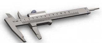
Determination of readings by vernier
To determine the readings of a caliper, it is necessary to add the values of its main and auxiliary scales.
- The number of whole millimeters is counted on the bar scale from left to right. The pointer is the zero stroke of the vernier.
- To count fractions of a millimeter, it is necessary to find the vernier stroke that most accurately matches one of the strokes of the main scale. After this, you need to multiply the serial number of the found vernier stroke (not counting zero) by the value of its scale division.
The measurement result is equal to the sum of two quantities: the number of whole millimeters and fractions of mm. If the zero line of the vernier exactly coincides with one of the lines of the main scale, the resulting size is expressed as an integer.
The figure above shows the readings of the ShTs-1 caliper. In the first case they are: 3 + 0.3 = 3.3 mm, and in the second - 36 + 0.8 = 36.8 mm.
Vernier with 0.05 mm division
The instrument scale with a division value of 0.05 mm is presented below. For example, two different indications are given. The first is 6 mm + 0.45 mm = 6.45 mm, the second is 1 mm + 0.65 mm = 1.65 mm.
Similar to the first example, you need to find the strokes of the vernier and the rod that exactly match each other. In the figure they are highlighted in green and black, respectively.
Vernier calipers - classification and marking
The measuring instrument, a caliper, can be of 3 types and about 8 standard sizes, at least according to domestic regulatory documents
Moreover, when purchasing any precision instrument, it is important to focus on the standards by which it is manufactured and calibrated. It is divided into types depending on the indicator of the measured value from which we take the required numbers
These can be vernier (ShTs), dial (ShTsK) and digital (ShTsTs) calipers. In the first case, we will have to run our eyes over both scales, count the divisions and report the result. In the second case, we will see numbers on a mechanical scale with a moving arrow, but in the third case, we will be shown the finished result on the display.
Within these types, further subspecies can be divided depending on the design and length of the main line. For example, you can divide tools by the type of material from which they are made. An example of a hard alloy tool is ShTsT-I. There are differences in the design of the jaws or additional accessories. Thus, ShTs-I and ShTs-III differ in the location of the jaws; in the first case it is bilateral, and in the second it is unilateral. But the ShTs-II has a micrometric feed frame, which will make marking easier if you need to transfer your measurements to another plane. There is no point in discussing the differences in standard sizes for a long time; one has only to say that the larger the ruler, the greater the error in the obtained values.
Photo of the ShTs-2 caliper, antok.by
Photo of caliper, antok.by
Photo of digital caliper, tehnoalat.rs
Photo of dial caliper, tehnoalat.rs
Photo of digital composite caliper, tehnoalat.rs
Mechanical caliper device
The design of a double-sided caliper with a depth gauge is shown in the figure. The measurement range of this instrument is 0-150 mm. With its help, you can measure both external and internal dimensions, the depth of holes with an accuracy of 0.05 mm.
Essential elements
- Barbell.
- Frame.
- Sponges for external measurements.
- Sponges for internal measurements.
- Depth gauge ruler.
- Locking screw for fixing the frame.
- Vernier scale. Serves to count fractions of millimeters.
- Bar scale.
The jaws for internal measurements 4 are knife-shaped. Thanks to this, the hole size is determined on a scale without additional calculations. If the caliper jaws are stepped, as in the ShTs-2 device, then when measuring grooves and holes, their total thickness must be added to the readings obtained.
The reading value of the vernier may differ for different instrument models. So, for example, for ShTs-1 it is 0.1 mm, for ShTs-II it is 0.05 or 0.1 mm, and the accuracy of devices with a vernier reading value of 0.02 mm approaches the accuracy of micrometers. Design differences in the design of calipers can be expressed in the shape of a moving frame, measurement ranges, for example: 0–125 mm, 0–500 mm, 500–1600 mm, 800–2000 mm, etc. The accuracy of measurements depends on various factors: the reading value on the vernier, work skills, and the good condition of the instrument.
How to measure pipe diameter
When laying pipelines, installers are faced with various options for their location, which often determines how the pipe is measured. To find the necessary parameters at home, they usually use any measuring instrument that is at hand, and, if necessary, a simple calculation formula.
In production, measurements are mainly carried out for control by more complex, high-precision instruments (for example, a laser meter or a ruler, a circummeter, is used).
Rice. 12 Methods of installing fittings on PEX pipes: compression, tension couplings, press fittings, push fittings
How to measure the diameter of a pipe with a ruler and tape measure
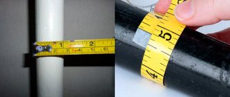
A tape measure or ruler can almost always be found in households; they can be used to find out the parameters of a pipe cut across. To determine the dimensions, apply the tools to the pipe end and look at their scale, visually comparing its readings with the cross-section of the product. The accuracy of this method is low - it is difficult to take measurements accurately diagonally.
If communications are located in hard-to-reach places and are not cut, it becomes too difficult to accurately determine the diameter of the pipe with a tape measure or using a ruler. You will have to attach rectangular parts to the wall around the pipe shell on both sides and measure the distance between them as close to the shell as possible to reduce the error.
Rice. 13 How to measure the diameter of a pipe with a tape measure and ruler
Using a caliper
A caliper is a fairly convenient measuring tool for determining internal and external dimensions in a circle up to 150 mm with an accuracy of 0.1 mm. Modern devices, in addition to a mechanical scale, may have an electronic or dial indication.
It is convenient to use a caliper to measure the pipeline in hard-to-reach places, touching or even partially located in the wall, less than half of the screed. An accuracy of 0.1 mm is quite acceptable for any business purpose.
Even more accurate readings can be obtained by using a micrometer, however, if calipers are occasionally found in the household, then a micrometer is an expensive industrial control and measuring device, the high accuracy of whose readings is not needed in everyday life.
Rice. 14 How to measure the diameter of a pipe with a caliper
How to measure the diameter of a pipe using string and the formula
Sometimes solving the problem of how to measure the diameter of a pipe is difficult due to the inconvenience of taking measurements and the large overall dimensions of the pipeline - in these cases, a combined method can be used.
To do this, tie the pipe with thread or rope (several turns can be made), and mark them with a marker or pen. Then lay the thread on the table and measure the distance between the marks. The resulting value is divided by pi, equal to 3.142, and the desired size is obtained. This method of calculating the diameter allows you to find out the parameters of the pipeline with higher accuracy thanks to the thousandth values of the number pi and the greater extent of the circumference than the directly measured parameter.
Sometimes it is difficult to determine the internal pipe size for a number of reasons; in this case, the problem of how to determine the pipe diameter is solved using a complex method. First, measure its external size in a circle, then the thickness of the wall, after which, using the formula, divide the first indicator by the number pi and subtract double the thickness of the shell from it.
Rice. 15 How to measure the diameter of a pipe using measuring tapes and the appearance of the circometer
Measuring tapes
One of the fastest ways to measure the diameter of a pipe is to use tapes with dimensional scales. Sometimes, for these purposes, a construction tape is used, which has a flexible tape with marked divisions and length values.
In everyday life, a measuring tape is often used, which is used to determine the size of clothes in sewing; it can also be used similarly to a tape measure. After measuring the length along the outer circle, a simple calculation is carried out: the result is divided by 3.142 and the outer diameter is found in this way.
An analogue of household tape meters is an industrial circummeter - a special device with a graduated flexible steel strip for measuring circumference lengths.
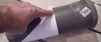
Photo copy method
The photographic method allows you to find out the parameters of the pipeline in extreme and emergency conditions in the absence of lighting, poor access to communications, and a limited time interval. When measuring pipe diameters using photography, place a tape measure with divisions or any object that can be taken with you next to the pipe, and take a photograph with a camera or cell phone. Then, under calm conditions, the photograph is analyzed, comparing the dimensions of the digital tape measure or the dimensions of the object with the parameters of the pipe.
Rice. 16 Comparative table of diameters of water pipes made of various materials
Thanks to the standard range of standard sizes of steel, copper, and polymer pipelines, the problem of how to find out the diameter of a pipe is, in most cases, successfully solved by studying the relevant state standards. If for some reason there is a need for measurements, for household purposes it is quite possible to get by with a ruler, tape measure, use measuring tapes or a piece of string, obtaining the desired result using a simple formula.
The procedure for carrying out measurements, checking serviceability
Before work, check the technical condition of the caliper and, if necessary, adjust it. If the device has warped jaws, it cannot be used. Nicks, corrosion and scratches on working surfaces are also not allowed. It is necessary that the ends of the rod and the depth gauge ruler coincide when the jaws are aligned. The instrument scale must be clean and easily readable.
- The caliper jaws are pressed tightly against the part with little force, without gaps or distortions.
- When determining the outer diameter of a cylinder (shaft, bolt, etc.), make sure that the plane of the frame is perpendicular to its axis.
- When measuring cylindrical holes, the jaws of the caliper are placed at diametrically opposite points, which can be found by focusing on the maximum scale readings. In this case, the plane of the frame must pass through the axis of the hole, i.e. Measurement along the chord or at an angle to the axis is not allowed.
- To measure the depth of a hole, a rod is placed at its edge perpendicular to the surface of the part. The depth gauge ruler is pushed all the way to the bottom using a movable frame.
- The resulting size is fixed with a locking screw and the readings are determined.
Measuring fasteners. Size of bolts, nuts, screws, studs, cotter pins
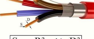
The main parameters that determine the type and size of fasteners are: diameter, length and thickness (or height). Most of today's Russian-language reference books, drawings and design documentation use symbols borrowed from the English language and alphabet. Thus, the diameter of a fastener is usually denoted by a large or small Latin letter “D” or “d” (short for Diameter), the length of a fastener is usually denoted with a large or small Latin letter “L” or “l” (short for Length) , the thickness is denoted by the capital or small Latin letter “S” or “s” (short for the English Stoutness), the height is denoted by the capital or small Latin letter “H” or “h” (short for the English High). Let's look at the features of measuring the main types of fasteners.
Bolt Measuring
Bolts with metric threads are designated in the documentation in the MDxPxL format, where:
- M - metric thread icon;
- D is the diameter of the bolt thread in millimeters;
- P - thread pitch in millimeters (there are large, small and especially small pitches; if the pitch is large for a given thread diameter, then it is not indicated);
- L is the length of the bolt in millimeters.
To determine the type and size of a particular bolt, you need to visually establish its type by comparing the bolt design with one of the standards (GOST, DIN, ISO). Then, having found out the type of bolt, sequentially determine all the listed dimensions. To measure the bolt diameter, you can use a caliper, micrometer, or a straight edge.
The accuracy of a certain external thread diameter is controlled using a set of “PR-NOT” (pass-no-go) gauges, one of which should be easily screwed onto the bolt, and the other should not be screwed on at all. The length of the bolt can be measured using the same calipers or ruler.
A tool such as a pedometer is commonly used to determine the thread pitch on a threaded fastener.
You can also measure thread pitch by measuring the distance between two threads using a caliper.
However, the accuracy of this method is satisfactory only for large thread diameters. It is more reliable to measure the length of several thread turns (for example, 10) with a caliper (or, in extreme cases, a ruler) and then divide the measurement result by the number of measured turns (in the example, by 10). The resulting number must coincide exactly (or almost exactly) with one of the values of the thread series of thread pitches for a given thread diameter - this reference value is the desired thread pitch. If this is not the case, then most likely you are dealing with an inch thread - determining the thread pitch requires further clarification. Depending on the geometric configuration of the bolt, the method of measuring its length may differ, and all bolts can be conditionally divided into 2 groups:
- protruding head bolts
- countersunk bolts
How to use a caliper: step-by-step instructions
Vernier calipers are used to determine outer and inner diameters, linear dimensions, depths of grooves and holes, and distances between shoulders. Some modifications allow markings to be applied to the surfaces of workpieces. The tool is used to measure workpieces in mechanical and metalworking production areas, to control the production of wear surfaces when repairing equipment, and due to its ease of use, it is used in home workshops.
How to store the tool
It is best to store the caliper in a special tool case. It is usually protected by special gaskets. In this case, even if you drop the case, the instrument will not be damaged.
After each measurement, the device must be put back in the box.
For preventative cleaning, remove the device from the case, loosen the clamps as much as possible, spreading the legs, wiping all measuring and moving elements.
If you still have questions about working with the device, the following video will help answer them.
Watch this video on YouTube
Previous Household Appliances Thermal imager for inspecting buildings and structures: catching heat correctly Next Household Appliances Replacing a bearing in a washing machine: how to save on calling a technician
Vernier caliper design
Shown in Fig. 1 caliper type ШЦ-1 consists of:
- Barbells.
- Framework.
- Measuring scale.
- Upper lips.
- Lower lips.
- Depth gauge.
- Vernier scales.
- Clamping screw.
The choice of caliper for a specific task is determined by the dimensions, design features of the part and requirements for dimensional accuracy. The tools differ in the following parameters:
- Measuring range . The length of the scale on the rod ranges from 125 to 4000 mm.
- Accuracy . Common modifications have an error of 0.1, 0.05, 0.02 and 0.01 mm.
- Functionality . There are calipers with and without a depth gauge.
- The number and shape of measuring surfaces. The jaws of single-ended and double-ended instruments are available in flat, pointed or rounded shapes.
- The design of the reading device . It can be vernier, mechanical, clock type or electronic.
Vernier calipers are made of wear-resistant tool steels, and their measuring surfaces can be reinforced with carbide tips. To mark parts, cutters are installed on non-sharpened jaws (Fig. 2), complete with holders and clamping screws.
Checking and adjusting calipers
Calipers, like any measuring instrument, can lose their accuracy due to mistuning, mechanical damage and natural wear.
The straightness of the tool, from the side surfaces and ribs, is checked with a straight edge for the absence of clearance.
There should be no light gap between the connected jaws of the caliper, and the leftmost mark on the vernier scale must strictly coincide with the zero mark on the rod scale. Falling a caliper, even from a small height, can cause the jaw to bend relative to the rod.
Checking tool straightness
Even the slightest bend creates an unacceptable gap between the jaws, leading to incorrect measurements. Such bends can be identified by checking with a curved square of an accuracy class of at least second.
Checking the serviceability of the sponges using light
There should not be a light gap between the square pressed to the rod and the measuring surfaces of the jaws, but as can be seen in the photo, there is one.
Identified bends can be corrected by lightly striking it in the desired direction with a copper tool. After each impact, a square check should be made for clearance. And so on until the perpendicularity of the sponge to the bar is completely restored.
The gap between the closed jaws is visible to the light
With the measuring jaws aligned and aligned, the leftmost mark of the vernier scale should coincide with zero on the rod scale.
The mechanically fixed vernier allows for correction through adjustment. Checking the cylindrical jaws for wear on calipers of the ShTs-2 and ShTs-3 types can be done with a micrometer.
Checking the clearance of the jaws for internal measurements on the ShTs-1 caliper will not lead to an objective assessment, due to the fact that these jaws can overlap each other.
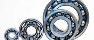
They can be checked by measuring calibrated holes, which can be used as holes in new bearings.
With the jaws closed, the depth gauge must be strictly level with the end of the rod. The accuracy of the depth gauge is checked by measuring flatness, in which the measurement result should be zero.
Measurement order
The tool and part need to be prepared for work: remove dirt, bring the jaws together and make sure that the readings correspond to “0”. To measure the outer diameter or linear dimension you must:
- spread the sponges by moving the frame;
- move until it fits snugly against the countersurfaces;
- fix the position of the frame with a locking screw;
- bring out a caliper to evaluate the results obtained.
To measure the internal size, the jaws are brought to “0” and then moved apart until they come into contact with the countersurfaces. If the design features of the part allow you to see the scale, then the readings are read without fixing or removing them.
Measurements of the dimensions of the pattern on the protectors
How to measure tire tread if you need to assess the degree of wear? A depth gauge will help, which takes measurements along the entire tire tread. It should be taken into account that wear is almost always uneven, and the number of measurements should be at least 3...5, and on evenly distributed areas of the tire tread for assessment. Before measurements, the tire should be thoroughly cleaned of dirt, dust and fragments of small stones stuck inside.
Measuring tire tread with a digital depth gauge
Sometimes you need to solve the problem of how to measure the tire tread with a caliper to determine the degree of uniformity of wear. This establishes the wear of the tread tires not only in depth, but also along the radius of transition from the circle of protrusions to the circle of depressions. They do this. The depth of the pattern on the new tire tread is measured, and then the linear size of the visually changed zone on the used part. The difference will determine the degree of wear and help you make the right decision about replacing the wheel.
All measurements are made with a depth gauge, which must be installed strictly perpendicular to the tire tread.
Measuring tread wear with a Columbian
Reading results
Vernier scale
The number of whole millimeters is counted from the zero division on the staff to the zero division of the vernier. If they do not match, then the size contains fractions of a millimeter corresponding to the accuracy of the tool. To determine them, you need to count on the vernier from zero to the line that coincides with the mark on the bar, and then multiply their number by the division value.
Figure 4 shows the dimensions: a – 0.4 mm, b – 6.9 mm, c – 34.3 mm. Vernier division value 0.1 mm
By hourly indicator
The number of whole millimeters is counted on the bar from zero to the last mark not hidden under the frame. Shares are determined by an indicator: the number of the division on which the arrow stops is multiplied by its price.
Figure 5 shows the size 30.25 mm. The indicator division value is 0.01 mm.
By digital display
There is no need to count here, the size is shown on the display.
To determine the internal size taken with a tool with radius measuring surfaces (lower jaws in Fig. 3), their thickness, which is indicated on the fixed jaw, is added to the readings on the scale. To calculate the outer size taken with a caliper with cutters (Fig. 2), their thickness is subtracted from the readings on the scale.
Metric and inch units
Before measuring the size of the assortment, you should take into account that the technological features of laying and carrying out calculations when working with steel and plastic lines are different.
For this reason, it is necessary to first gain an understanding of the standard sizes of pipe-rolling materials for pipelines, and only then measure them. Without this knowledge, it is impossible to determine the size of the assortment in millimeters or inches.
Rolled steel pipes are primarily determined by their internal volume, measured in inches. In accordance with these units, you can find the names “inch” and “half-inch” pipe materials. One inch is equal to 25.4 mm, and half of it is correspondingly defined as 12.7 mm.
Plumbing fixtures are in no hurry to measure the outer diameter. Often installation can be done without it. It is necessary to measure this value in cases where it is necessary to measure a pipeline fastened with joints on a threaded connection.
It is usually cut on the outer part of the tubular product, and its size depends on the dimensions of the wall of the tubular product. During these actions, you should remember that if you measure pipes with different internal volume indicators, the wall size will be different.
To make it easier to measure and calculate the amount of materials needed for a pipeline, you can use a special thread system to indicate the external volume of pipe products. These values differ from the usual indicator, which can be measured in mm.
To correctly determine the size of pipe products in millimeters or find out their dimensions in inches, you need to take into account the following information.
For example, if the diameter of the metric thread knurling is designated M16, then the tubular product has an outer volume of 16 mm. In the version with pipe threads, all this is different. In inches these calculations are slightly different.
The outside diameter of a half-inch product does not reach 21 millimeters, and its thread knurling is the same in size. And this product gets its name “half-inch” because of the volume inside. In inches this value is denoted as ½. To make it easier to convert inches to mm, it is recommended to use special tables.
Marking
A regular caliper with pointed measuring surfaces copes with basic marking operations. By pressing one jaw against the side of the part, you can use the tip of the second to draw a line on the surface perpendicular to it. The line turns out to be equidistant from the end and copies its shape. To draw a hole, you need to mark its center: the recess serves to fix one of the jaws. Any technique of descriptive geometry can be used in a similar way.
Carbide tips and cutters leave noticeable scratches on parts made of steels with a hardness above 60 HRC. There are also narrow-profile calipers designed exclusively for marking.
Why do measurement errors occur?
The most common errors that reduce the accuracy of measurement results with a working instrument:
- Excessive pressure on the frame causes misalignment relative to the rod. The same effect is obtained if, when measuring with the lower jaws, the caliper is brought together by the upper jaws.
- Installation of jaws on fillets, chamfers and roundings.
- Distortions during positioning.
- Instrument calibration violation.
The first three mistakes most often arise from lack of experience, and go away with practice. The latter must be prevented at the stage of preparation for measurements. The easiest way is to set “0” on an electronic caliper: there is a button for this (in Fig. 6 the “ZERO” button). The hour indicator is reset by rotating the screw located at its bottom. To calibrate the vernier, loosen the screws securing it to the frame, move it to the desired position and fix it again.
§ 17. Measuring the dimensions of parts using a caliper
When manufacturing parts from thin sheet metal and wire, you can use the simplest control and measuring tools: a ruler, a bench square, etc. To measure and control parts with greater accuracy, calipers are used. They are designed to measure the external and internal dimensions of parts and the depth of holes, grooves, and grooves. Vernier calipers come in different types and differ in the range and accuracy of measurement.
Figure 63 shows the ShTs-1 caliper with measurement limits from 0 to 125 mm and accuracy of 0.1 mm. It consists of a rod 1 having a scale of 6 with millimeter divisions. A movable frame 4 moves along the rod, which can be secured in the desired position with a clamping screw 3. A depth gauge 5 is attached to the frame.
Rice. 63. Caliper ШЦ-1: 1 — rod; 2 - jaws for internal measurements: 3 - clamping screw for fixing the frame; 4 — movable frame; 5 — depth gauge; 6 — rod scale; 7 - vernier; 8 — sponges for external measurements; 9 - measured parts
The lower jaws 8 are used to measure external dimensions, the upper 2 are used to measure internal dimensions. A depth gauge measures the depth of grooves and holes.
How is it possible to measure tenths of a millimeter if the caliper scale has millimeter divisions? For this purpose, an auxiliary scale called vernier 7 is used. The length of the vernier is 19 mm. The vernier is divided into 10 equal parts, therefore, the price of each division is 1.9 mm.
With the jaws closed, the zero strokes of the scale of the rod and the vernier coincide (Fig. 64), and the tenth stroke of the vernier is combined with the nineteenth stroke of the millimeter scale.
Rice. 64. Bar scale and vernier
Please note that the first line of the vernier does not reach the second line of the rod scale by exactly 0.1 mm (2 – 1.9 = 0.1). This allows measurements to be taken with an accuracy of up to 0.1 mm
When measuring with a caliper, an integer number of millimeters is counted on the millimeter scale of the rod to the zero line of the vernier. Tenths of a millimeter - on the vernier scale from the zero mark to the vernier stroke that coincides with any stroke of the millimeter scale (Fig. 65).
Rice. 65. Examples of measuring with a caliper. The position of the rod and vernier scale when measuring dimensions: a - 0.4 mm; 6 - 6.9 mm; in — 34.3 mm
Remember!
A caliper is an expensive measuring tool that requires careful handling.
Rules for handling vernier calipers
Before starting work, wipe the caliper with a clean cloth to remove grease and dust.
Do not clean the tool with sandpaper or a knife.
Do not place the tool on heating devices.
Only clean parts without burrs, burrs or scratches can be measured.
The jaws of the caliper have sharp points, so you need to be careful when measuring.
Do not allow the caliper jaws to become distorted. Fix their position with a clamping screw.
When reading the readings on the measuring scales, hold the caliper directly in front of your eyes.
In enterprises, calipers are one of the main measuring tools. It is used by workers of various specialties and supervisors of machine tools and plumbing operations. Currently, calipers with digital indicators (battery powered) are increasingly used, allowing parts to be measured with an accuracy of 0.01 mm.
Getting to know the professions
The controller of the technical control department (QCD) is a specialist who is responsible for the quality of manufactured parts at the enterprise. He's keeping an eye on it. so that the manufactured parts exactly correspond to the drawings. This is a very responsible job, since if a defective part that does not correspond to the drawing gets into the product, the product will quickly fail. Quality control inspectors must know the rules for setting up and regulating instrumentation and instruments, methods for checking the quality of surfaces, rules for accepting parts, etc.
Laboratory and practical work No. 17
Measuring the dimensions of parts with a caliper
- In your workbook, complete the sketch of the stepped roller given by the teacher (Fig. 66).
- Measure each bead size with a caliper and record the results in millimeters in a table.
- Put the resulting dimensions on the sketch made in your workbook.
Rice. 66. Sketch of the “stepped roller” part (to paragraphs 1-3)
Testing your knowledge
- What are the main parts of a caliper?
- How many measuring scales does a caliper have?
- What measurements can you take with a caliper?
- How many times is the accuracy of measurement with a caliper greater than the accuracy of measurement with a ruler?
- How do you use a caliper to measure whole and tenths of a millimeter?
What can you measure with a caliper?
1) External size of the part (item)
For example, using external measuring jaws you can measure the outer diameter of a pipe:
2) Thickness of the part (object)
For example, you can also measure the pipe wall thickness using jaws for external measurements:
3) Internal size of the part (item)
For example, using internal measuring jaws you can measure the internal diameter of a pipe:
4) Depth of the part (object)
The caliper has a special depth gauge that allows you to measure the depth of the part:
Measurement by copying - photography
This method can be useful when there is no access to the pipe at all. It is suitable for both small and large diameter pipes. To scale, you will need to attach a ruler or any other large-scale object to the pipe, the dimensions of which are initially known. Then the pipe with the attached objects is photographed - and the resulting image will allow an analysis of the diameter of the pipe, based on a comparison of the sizes of a large-scale object for comparison.
Measuring labor using the copying method will allow you to determine the diameter of pipes located in hard-to-reach places.
In particular, this technique is used if it is necessary to calculate the dimensions of pipes in a car without the need to unload it. It will be possible to take just one photo and send the train on its way. Otherwise, it would be necessary to measure each pipe separately.