The quality of welding work and welded joints greatly influences the strength of structures or the tightness of tanks. Failure of welds to meet the specified characteristics leads to structural failures with catastrophic consequences, the same applies to systems operating with vessels and pipelines under pressure.
Therefore, after welding work, the finished product is subjected to testing and inspection to detect defects in welded joints.
All welding quality control procedures are defined by GOST or governing documents. They also indicate acceptable error limits. After the tests, a report and protocols with the measurement results are drawn up.
Verification methods
Quality control of welding work performed in production can be destructive or non-destructive. The first methods are used selectively. One or more products from a large batch, or part of a metal product in a building structure, is checked.
It is tested on various parameters using a specific test report. But mainly they use special devices or materials to check the quality of welded joints without destroying the structure.
The main methods of non-destructive welding quality control are:
- visual;
- capillary;
- permeability test;
- radiation;
- magnetic;
- ultrasonic.
There are other methods and types of welding quality control, but due to their specificity they have not become widespread.
Checking the condition of welds is not a one-time act, it is the resulting stage that shows how the quality control system at the enterprise works.
To minimize defects in welding joints, operational control of the work is carried out. Certification is carried out regularly, at which the commission first gives permission to weld the control joint. When welders pass this test, their theoretical knowledge is tested.
Before starting work, the welder’s qualifications are checked; he must have a certificate for the right to weld certain grades of steel and a work permit.
A welding engineer and a controller from the technical control service check the quality of assembly, the condition of the edges, the performance of the welding machine, and controls the heating temperature, if this is provided for in the regulatory and technical documentation.
Quality control of welding materials is carried out from the moment they arrive at the enterprise and before use at the welding station. The electrodes are checked at each stage of storage and use, and if necessary, they are calcined.
During the actual work, check what welding mode is used: arc welding, argon arc or another type of welding. Check the order of sutures, the dimensions of the layers and the entire connection.
If special requirements are provided for in the design and technical documentation, then their implementation. Upon completion of welding, checks for the presence of the welder’s mark.
Control method
The quality of welds is checked by trained and certified specialists who have received the qualification of experts in the appropriate control method. At construction sites and enterprises that need to regularly check the condition of welded joints of metal structures or provide similar services as a contractor, divisions responsible for performing the specified work have been created. The methods used for testing welded joints are divided into two groups: destructive and non-destructive. In most cases, methods are used that do not involve destruction of connections.
Destructive types of testing of welded joints are relevant in the following cases:
- to check test samples before performing the main welding of elements;
- when producing mass products, a certain number of copies from the total batch are tested.
Control is carried out using specialized equipment, the operation of which requires personnel to have appropriate knowledge and skills. Devices are subject to periodic verification to ensure compliance with established error tolerances, in accordance with current legislative standards.
Visual and measuring control
There is no need to use special equipment to carry out visual and measuring inspection. Control carried out by an expert using basic measuring instruments (calipers, templates, tape measures, probes, rulers, squares, magnifiers and lux meters) is sufficient.
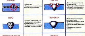
The specialist inspecting the weld must exclude the following defects:
- discontinuity;
- heterogeneous structure;
- cracks;
- voids;
- pores;
- fistulas;
- chips;
- uncooked areas;
- uneven section;
- deviation from the geometry of the weld profile.
The presence of internal defects can be judged based on characteristic external signs. Identified defective areas are measured to verify that their dimensions comply with the permitted tolerances according to the standards. Additionally, the height and width of the weld bead are determined. It is impossible to ensure complete objectivity during a visual inspection. The results depend on the vigilance and qualifications of the expert, his experience and knowledge. Individual details can be viewed through a magnifying glass. Experts also use compact flashlights to illuminate necessary areas. Identified defects are noted for their subsequent elimination. If the quality of some areas is in doubt, additional verification by other control methods is required.
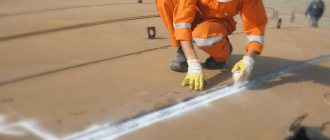
Capillary method
This technique is based on the ability of certain liquid media to penetrate into the metal through tiny pores that are inaccessible to the naked eye. The work is carried out using consumables - paint or chalk. These substances are used to treat the surface to enhance visualization. Additional components are added to the liquid used to color the composition. They produce substances for the capillary control technique (penetrants) that have luminescent properties. When light hits such a composition, the brightness of the reflected light flux increases many times over. The technique can be used to check the quality of welds of any metals. The results are assessed by the nature of the pattern after applying the penetrant. The more colored the metal surface is, the worse the welding is done. This method is more often used to test materials that are sensitive to temperature changes due to large linear shrinkage during the cooling process.
Checking the tightness of welds
The tightness of welds is important when it comes to vessels operating under high pressure, pipelines or hydraulic systems. This technique has received numerous names.
This control method is called:
- bubbly;
- pneumatic testing;
- leak detection;
- hydrotesting, etc.
The method is divided into two types: pneumatic and hydraulic, depending on the nature of the medium used during the test. But in both varieties they use a single technique, similar to the capillary control method. The difference is that in this case, welding seams are checked by supplying a gas or liquid mixture under pressure.
Pneumatic method
With this method, compressed gas or air is pumped into the area being tested. A soap solution is applied to the surface of the seam to form a film. The solution is prepared using a soap to water ratio of 1 to 4. Discontinuities in the seam are indicated by swollen bubbles.
The use of the following types of pneumatic method is provided:
- vacuum - by applying a soap solution, a vacuum is created on the other side of the welded joint; used to identify through defects;
- submersible - the welded section is completely immersed in a container filled with soap solution; the presence of defects is determined by the released air bubbles.
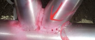
If the control operation is carried out in the cold, the water is replaced with an alcohol solution with non-freezing properties. Ammonia can be used as a gaseous medium. Before testing, the area is wrapped in paper. Defects will be indicated by visible red spots.
Hydraulic method
The features of the hydraulic method are based on the ability of a liquid medium to create pressure. The welded element is immersed in oil or water for a certain period of time. During the immersion process, the liquid is absorbed through the pores into the substance. Based on its secretions, after removing the part from the solution, you can determine the presence of internal voids by first tapping the surface with a hammer. To diagnose containers or pipelines, communications are filled with liquid under pressure. The technique is very simple but effective. If defective areas are identified, the corresponding areas need to be digested. Then a re-check is carried out.
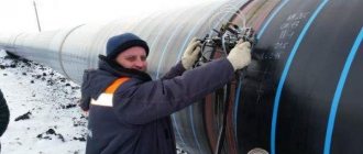
Magnetic flaw detection
The principle of magnetic flaw detection is the use of the ability of a metal to be magnetized when exposed to a magnetic field. Considering the properties of materials, this method of weld inspection is not suitable for non-magnetic alloys of copper, zinc, brass and others.
Features of magnetic flaw detection:
- through the device, the weld is exposed to a constant magnetic field;
- as a result, electromagnetic force lines are formed, under the influence of which small particles of material acquire the ability to move and occupy a fixed position;
- the surface of the seam is covered with crushed metal powder;
- with a uniform structure of the pattern, we can conclude that the weld is of high quality; the presence of cracks and slag inclusions can be determined by the distortion of the resulting picture.
This inspection method is effective for detecting even the most minor defects. The only negative is the impossibility of identifying the problem area if the crack is directed along the magnetic field lines.
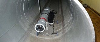
Ultrasonic flaw detection
Ultrasound can reveal signs of a non-uniform structure of welded metal in a weld. In the presence of voids, the direction of passage of the waves changes, and the generated radiation does not reach the control device. By measuring the resulting deviation, the presence and nature of the defect are determined. Depending on the type of violation, certain distortions of the ultrasonic flow are recorded. To identify the defect, the results are compared with control illustrations. This method is used quite often. Unlike magnetic flaw detection, such inspection of welded joints is applicable for non-ferrous alloys.
Radiation method
Testing welds using the radiation control method requires strict adherence to safety measures to prevent harm to the health of personnel. This technique involves taking an x-ray of the welded area. For diagnosis, an X-ray machine is used, the design of which differs slightly from the device used in healthcare institutions.
The work is performed in the following sequence:
- install and turn on control equipment;
- the radiation created penetrates the metal; in the presence of voids, X-rays change direction, deviating from the given trajectory;
- on the other side of the seam, the results are recorded on a special film;
- the characteristics of the connection are determined by the density of the detected radiation.
This innovative and progressive technique is not safe. To carry out monitoring, special instruments and consumables are required. Personnel must be trained to operate the equipment. An excessively long stay in the control zone has an adverse effect on the health of the worker performing diagnostic operations. They produce computer devices that process inspection results and display the results on a monitor. The device automatically decrypts the received data, ensuring quality control of welds and connections with high research accuracy.
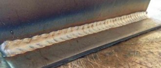
Visual inspection
Any quality check of welds begins with visual inspection. All 100% of welded joints are inspected. First, check the geometry and shape of the seam.
Visual inspection helps to identify, along with external ones, some internal defects. Thus, seam beads of variable dimensions and uneven folds indicate lack of fusion that occurs due to frequent breaks in the electric arc.
Before starting work, remove slag, scale and other contaminants from welded joints. To better see the defects, the seams are treated with nitric acid (10%). This gives the seam a matte finish, making it easier to find flaws.
After acid treatment, it is necessary to thoroughly wipe with alcohol to prevent its harmful effect on the alloy.
To improve the quality of the inspection, you can use a flashlight and an optical magnifier. To control geometric dimensions, calipers and templates are used.
PVK - capillary method
This type is used when it is necessary to check the quality of welds for defects that are not visible due to their small size. Penetrant control is performed using special penetrating compounds—penetrants. These substances have high fluidity and fill small defects allowing them to be identified.
This method is used to check welds and critical products after manufacturing (for example, a live steam manifold) during incoming inspection, and I also check operating equipment during operation.
The process is quite simple and is therefore often used in contrast to similar magnetic control. Let's consider the control process itself.
Initially, the surface that needs to be checked is cleaned to a metallic shine with a cord brush or sandpaper so that the surface does not have too much roughness (not higher than Ra 3.2).
Next, you can treat the surface with the cleaner that comes with the penetrants. The penetrant set consists of three cans similar to cans of paint. One of them is a cleaner, the second is the penetrant itself, and the third is a developer.
After applying the cleaner, remove it with a rag and apply penetrant to the dry surface. After this, the time necessary for the penetrant to penetrate is maintained. The time may vary depending on the temperature and manufacturer, but on average it is 10-15 minutes.
After which the penetrant is washed off from the surface. At this stage, you do not need to rub the surface too hard so as not to wash off the penetrant from the defect cavity.
Now the surfaces need to be wiped with a rag, this must be done delicately so that I can remove the penetrant from the defects.
Next, a thin layer of developer is applied to the already dry surface. The developer is applied in a thin layer from a distance of 200-300 mm (distance for a spray can). This is followed by drying, which takes from 10 to 20 minutes. Drying occurs due to the natural evaporation of the developer liquid. If you need to speed up the process, you can use a stream of warm air (heat it with a hair dryer).
After drying, the surface is inspected; there should be no red spots on the surface, which will certainly appear if the products have defects.
After completing the inspection, clean the product from the developer by wiping the surface with a dry cloth.
Capillary method
This control method uses the property of liquid to be drawn into very small capillaries. The speed and degree of penetration into the material is related to its wettability and the diameter of the capillaries. The alloy is more wetted and the capillaries are thinner - the liquid penetrates deeper.
The capillary method of weld quality control allows you to deal not only with any metals, but also with ceramics, plastic, and glass. Its main use is associated with the manifestation of external flaws that are impossible or difficult to detect with the naked eye. Sometimes, using, for example, kerosene, you can detect through defects.
The method is very simple, it has been working since the need to check welding seams arose. A special GOST 18442-80 has even been developed for it.
In the capillary welding quality control method, penetrants are used - substances that have low surface tension and strong color contrast.
By penetrating into defective areas and highlighting them, penetrants visualize welding flaws. They are made from water, kerosene, transformer oil and other liquids.
The most sensitive penetrants can show defects as small as 0.1 microns in diameter. The capillary welding quality control method is effective for defects up to 0.5 mm wide. It does not work for large pore diameters or cracks.
The method using penetrants involves cleaning the surface, applying a control liquid and revealing flaws. A very effective way to control welded joints is using kerosene.
Despite the variety of welding quality control devices, testing by this method is still used. A chalk solution is applied on one side, time is allowed to dry, then the seam on the other side is lubricated with kerosene. Defective areas appear after a few hours in the form of dark spots.
Capillary technique
This method is based on certain properties of liquids that have low surface tension values. These liquids do not collect in separate drops, but are constantly in a fluid state, filling holes and small grooves. This way you can identify surface flaws.
In this case, a special composition is applied to the welding joint, instantly filling the defects. After this, the seam is thoroughly inspected. For convenience when working, dye is added to the liquid.
Checking welded joints for permeability
If welding is used in the manufacture of tanks, tightness control is required. To do this, tests for tightness of connections are carried out. Quality control is carried out using gases or liquids.
The essence of the method is based on creating a large pressure difference between the outer and inner areas of the container. With through-hole flaws in the weld, liquid or gas will flow from an area of high pressure to an area of low pressure.
Depending on the substance used and the method of obtaining excess pressure, permeability control is carried out by pneumatics, hydraulics or vacuum.
Pneumatic method
The use of a pneumatic welding quality control method requires pumping the tank with some gas to a pressure of 150% of the nominal pressure.
Then all welds are moistened with soapy water. Bubbles form in places of leakage, which is very easy to fix. For better visualization, an ammonia additive is used, and the seam is covered with a bandage soaked in phenolphthalein. Red spots appear in areas of leakage.
If it is not possible to pump up the container, then use the blowing method. On one side the seam is blown under a pressure of at least 2.5 atmospheres, and on the other it is coated with a soap solution. If there is a defect, it will appear in the form of bubbles.
Hydraulic method
With the hydraulic method of welding quality control, the container being tested is filled with water or oil. An excess pressure is created in the vessel, which is one and a half times more than the nominal pressure.
Then, for a certain time, usually 10 minutes, the area around the seam is tapped with a hammer with a rounded head. If there is a through welding defect, a leak will appear. If the excess pressure is small, then the holding time of the tank is increased to several hours.
Destructive testing methods for welded joints
Destructive testing, as is already clear from the name, assumes that the controlled product will be destroyed.
It is carried out on specially welded samples using the same technology that will later be used on working products.
Let us list the main methods of destructive testing most commonly used in practice:
- Mechanical testing of welded joints.
- Dynamic testing of welds.
- Hardness measurement.
- Metallography.
- Stillscoping.
- Product hardness measurement.
You can find a complete list of all test methods by downloading it from the link here.
Mechanical static tests
This type of testing is carried out for welded joints of critical structures. Its essence lies in the fact that during testing the sample is either gradually loaded with a slight increase in load, or one-time without an increase.
The methods include the following tests:
- Compression;
- stretching;
- bend;
- twisting, etc.
Mechanical dynamic tests
Unlike static tests, during dynamic tests the sample is loaded with shock with a duration of impact on it of no more than hundredths of a second.
Dynamic tests include:
- Impact bending test at elevated temperatures;
- impact bending at low temperatures;
- impact bending at room temperature;
- impact test.
Hardness measurements
The hardness of welded joints is most often measured using the following methods: Brinell, Rockwell, Shore or Liebou.
The most commonly used method on objects is the Liebue method, which is based on changing the speed of a ball bouncing off the surface of the part during measurement.
The Brinell, Rockwell and Shore methods determine hardness by pressing a diamond prism, metal ball or steel needle into the surface of the test product, assessing the force and depth of pressing.
Magnetic flaw detection
The phenomenon of electromagnetism is used in magnetic flaw detectors. Each metal has its own degree of magnetic permeability. When passing through inhomogeneous materials, the magnetic field is distorted, which indicates the presence of foreign elements inside the structure.
This is used in the welding quality control instrument. It produces a magnetic field that penetrates the metal being tested. Inhomogeneities are recorded using magnetic particle or magnetographic methods.
In the first case, ferromagnetic powder is applied to the weld. Where the accumulation of powder occurs, there is most likely a lack of penetration, there is no continuous connection. The powder can be dry or wet, mixed with oil or kerosene.
In the second case, ferromagnetic tape is applied to the seam. It is then passed through a device where all anomalies recorded on the tape are analyzed and welding defects are determined.
The magnetic method of quality control has limitations associated with the very principle of operation of the device. It can only check the quality of welded joints of ferromagnetic materials, which do not include some steels and non-ferrous metals. Accordingly, this control method has limited application.
Eddy current testing
Eddy current testing is widely used in the aviation and nuclear industries, as well as in the production of rolled metal, castings and bearings. This method is good at identifying surface and subsurface defects. It can be used to measure the thickness of a coating or individual layers of material. The method is perfectly mechanized and automated. To perform it, there is no need to contact the surface and does not require a coupling liquid, unlike ultrasonic testing.
The method is based on changing the resistance and voltage in coils (eddy current transducers).
Ultrasonic flaw detection
Ultrasound is used to control welding quality. The operating principle of the device is based on the reflection of ultrasonic waves from the boundary between two media with different acoustic properties.
The sensor and emitter are tightly applied to the material being tested, after which the device produces ultrasound. It passes through the entire metal and is reflected from the back wall, returning to the receiving sensor, which in turn converts ultrasound into electrical vibrations. The device presents the received signal in the form of an image of reflected waves.
If there are any flaws inside the metal, the sensor will record a distortion of the reflected wave. It has been experimentally established that various welding defects manifest themselves differently on an ultrasonic flaw detector. This made it possible to classify them. With appropriate training, a specialist can accurately determine the type of defect in a seam.
The method of ultrasonic quality control of welded joints has become widespread due to its simplicity and ease of use, relatively inexpensive equipment, and safety of use compared to the radiation method.
The disadvantage of this method is the difficulty of deciphering the graphic image. Connection quality control can only be done by a certified specialist. It is problematic to use it for testing coarse-grained metals such as cast iron.
Price list
| Name of work/type of tests | Unit measurements | Price RUR, excluding VAT |
| Visual and measuring control of welded joints of reinforcement – longitudinal seams | 1 node | 200 rub. |
| Visual and measuring control of welded joints of reinforcement – butt joints of any diameter | 1 node | 100 rub. |
| Visual and measuring control of welded joints of sheet metal structures | 1 p.m. | 100 rub. |
| Visual and measuring control of welded joints of pipelines with a diameter | ||
| up to 50 mm from 50 to 100 mm from 100 to 300 mm from 300 mm to 600 mm from 600 mm to 800 mm from 800 mm to 1200 mm from 1200 mm to 1500 mm | 1 joint | 50 rub. 100 rub. 200 rub. 350 rub. 450 rub. 500 rub. 550 rub. |
| Ultrasonic testing of welded joints of pipelines with diameter | ||
| up to 50 mm from 50 to 100 mm from 100 to 300 mm from 300 mm to 600 mm from 600 mm to 800 mm from 800 mm to 1200 mm from 1200 mm to 1500 mm | 1 joint | 200 rub. 350 rub. 750 rub. 1300 rub. 1500 rub. 1700 rub. 2000 rub. |
| Ultrasonic testing of welded joints of sheet metal structures (thickness up to 20 mm) | 1 p.m. | 700 rub |
| Ultrasonic testing of welded joints of sheet metal structures (thickness 21-30 mm) | 1 p.m. | 1000 rub. |
| Ultrasonic testing of welded joints of sheet metal structures (thickness 31-40 mm) | 1 p.m. | 1200 rub. |
Radiation method
To control the quality of welding, radiation methods and devices are used. In essence, this is the same X-ray machine used in hospitals, or a device with a gamma radiation source, adapted for irradiating welded joints.
It is based on the ability of these rays to penetrate any materials. The intensity of penetration depends on the type of substances being tested. Thanks to this, an image characterizing the condition of this material remains on the photographic film behind the product under study.
All welding defects in the form of inhomogeneities are revealed on the film. The control method is very accurate, but expensive and harmful to people; it requires preparatory work to install protective screens and carry out organizational measures.
Radiation method
There are a couple of variations of this seam control technique:
- using gamma radiation;
- using X-rays.
The simplest solution is to check the workpiece with x-ray . This technology allows you to penetrate metal products, reflecting information on photographic film. In the resulting image you can see certain internal defects. Penetrating radiation makes it possible to detect edge displacement, gas pores, slag inclusions and other defects.
Gamma rays operate on a similar principle, but have the following advantages:
- isotopes do not lose their efficiency for a long time;
- the ability to study complex structures;
- increased radiation permeability;
- simpler and more compact equipment.
Remember that these radiations are very dangerous for the human body. Therefore, experienced specialists in protective equipment are allowed to perform such work. The workplace is also protected. For this purpose, screens, lead plates and other means are used.
Paperwork
A special magazine is provided for welding. It is the primary document drawn up in accordance with the requirements of SNiP. The design organization draws up a list of components in the metal structure that must be handed over to the customer with the preparation of welding documents.
In addition to the magazine, welding work is accompanied by a diagram of the joints, certificates for consumables (electrodes, flux or filler wire) and quality control reports on the outside of the product are attached.
If ultrasound or other specific studies were carried out, the results and conclusions on them are also attached.
All this allows us to talk about the quality of welding and reliability of the design. Only after the welding documentation has been submitted in full are further procedures for accepting the metal structures of the facility carried out.
Cracks
Defects refer to discontinuities and are local breaks in the weld or HAZ metal, as well as in the base metal. Cracks are considered unacceptable defects because they act as stress concentrators and reduce the strength of the welded joint. They appear for the following reasons:
- Incorrect grade of filler metal and/or flux. It is quite difficult to make a mistake with conventional quality structural steels. But tool and stainless alloys require a careful approach to the selection of wire and piece electrodes.
- Temperature violations. These include overheating of the HAZ, high cooling rates, and lack of heat treatment to relieve residual stresses.
- Hydrogen dissolved in a metal. The main reason for this phenomenon is moisture contained in poorly dried flux or electrode coating.
- Incorrect connection assembly. Rigid fastening of parts leads to the formation of cracks during cooling of the structure after welding.
Lack of fusion and lack of penetration
Failure of fusion is the failure of the connection between the base and filler metals or between individual weld beads. This discontinuity significantly reduces the strength of the connection and makes it unsuitable for use. Lack of penetration is an insufficient depth of penetration of the base metal. Lack of fusion and lack of penetration are often accompanied by pores and slag inclusions.
One of the main reasons for the occurrence of such defects is exceeding the optimal welding speed, when the weld pool does not receive enough thermal energy to melt the base metal. Lack of penetration and failure of fusion can be caused by other reasons, for example:
- improper cutting of edges;
- assembly with small gaps;
- poor quality cleaning of workpieces from rust and traces of oils;
- displacement of the electrode away from the weld axis;
- welding at low current values;
- insufficient heating of workpieces before welding (on semi-automatic machines under a layer of flux).
Foreign inclusions
Solid inclusions (single, linear or clusters) often get into the weld metal, the size of which can reach several millimeters. Like other defects, solid inclusions have a negative impact on the strength of the joint and are stress concentrators. According to the composition they are distinguished:
- Slag inclusions . They are formed if the slag formed during melting of the flux or coating does not have time to float to the surface of the weld pool and remains in the metal. One of the most likely reasons for the formation of slag inclusions is the use of thin-coated electrodes. An insufficient amount of slag leads to rapid cooling of the bath and crystallization of the weld. The formation of inclusions can also be caused by insufficient current, incorrect tilt of the electrode, or poor removal of slag when welding in several layers.
- Flux inclusions . Flux can remain in the metal if it has not had time to react and turn into slag. The main reason is an incorrectly selected particle size distribution.
- Tungsten inclusions . They appear during argon arc welding with a non-consumable electrode. Tungsten metal rarely gets into the melt. It is most often found in the form of oxides and carbides. The reasons for their entry are most often incorrect sharpening of the electrode and the presence of deposits on its surface. Tungsten metal can get into the weld when it comes into contact with molten filler metal.
- Oxide films and inclusions . Their presence indicates insufficient protection of the weld pool from atmospheric oxygen.
Most often, foreign inclusions are located inside the metal and do not come to the surface, so to detect them, welded joints are inspected using non-destructive methods.
Gas cavities
This group of defects includes closed and superficial pores, cavities, fistulas and craters. The presence of such defects is unacceptable in vessels operating under pressure and vacuum, in pipelines and containers for storing liquid and gaseous products. For other metal structures their presence may be acceptable. But each case must be analyzed individually in relation to operating conditions.
Pores and cavities are the result of the accumulation of gases in the weld metal, which do not have time to escape before it crystallizes. The longer the bath is in a liquid state, the lower the residual porosity of the joint, all other things being equal. Among the most likely causes of pore formation are:
- the presence of contamination on the surfaces being welded, wire, electrodes;
- high welding speed;
- increased humidity of the flux and electrode coating;
- drafts or air leaks through the gap between the parts being welded (when welding in protective gaseous environments);
- incorrect polarity;
- long arc welding (welder error).
When examining welds, the cause of pore formation is determined depending on the nature, size and location of the defect.
A fistula is a cavity in the form of a channel or tube. They are formed in places where gas escapes to the surface of the weld and have different lengths, diameters and spatial orientations. The reasons for their formation are sticking of the electrode, sudden break of the welding arc. Most often they occur when welding in vertical or overhead spatial positions.
In places where the arc breaks, craters and shrinkage cavities can also appear. The most common reasons for this phenomenon are errors in the actions of the welder: working at high currents, too large a volume of the weld pool.
Deviations in the geometry of metal structures
Warping makes it difficult to assemble equipment that includes welded parts and metal structures. To compensate for changes in their geometry, it is necessary to use workpieces with increased allowances for subsequent processing. Structures made of thin sheets and austenitic stainless steels exhibit the greatest tendency to deformation.
The participation of the welding laboratory in the development of technology allows us to reduce warping to an acceptable level. The most effective measures to reduce deformations are:
- increasing welding speed;
- double-sided welding with symmetrical groove (reverse deformation method);
- blowing, the use of copper pads to increase the rate of heat removal;
- welding in separate sections with intermediate cooling.
A complete classification of defects in welded joints is presented in the GOST R ISO 6520-1-2012 standard (Part 1).