Magnetic quality control of welds is a non-destructive method. The flaw detector checks finished joints and overlaps. Applicable to all types of welded joints. The flaw detector detects minor foreign inclusions: cracks, fistulas, pieces of slag, and other defects. The use of magnetic field dispersion methods is limited; for magnetic control, the metal must have a certain structure and the ability to be magnetized. Magnetic particle, magnetographic, and induction flaw detection are used only for monitoring welds on ferromagnetic alloys - carbon and low-alloy steels alloyed with cobalt, zinc, and manganese.
Main Magnetic Particle Testing Procedures
- Preparation. It is necessary to study the technological map, select indicator materials and equipment, and ensure proper metrological support. Determine the scheme and method of magnetization, type and magnitude of current.
- Magnetization. To detect surface defects, alternating or pulsed current is required. Direct and rectified current is effective for both surface and subsurface layers (at a depth of 2 mm). To prevent local heating and burn-through, it is recommended to carry out magnetization in intermittent mode. For this stage of magnetic particle testing, control samples (disks, rods, plates, pins and other workpieces) are used. With their help, it is much easier to select the exact value of the magnetizing current.
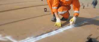
- Application of the indicator. It should cover the entire area under study, including hard-to-reach niches, blind holes, grooves, etc. When using aerosol cans, ensure that the distance between the nozzle and the surface is 200–300 mm.
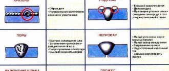
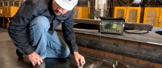
- Inspection. This stage of magnetic particle testing is performed after the excess indicator has drained off. Identified discontinuities are carefully examined using optical instruments and instruments. In stationary installations, automated systems for deciphering indicator patterns are used. When performing manual flaw detection, the length and coordinates of discontinuities are measured with rulers, squares and calipers made of non-magnetic materials. The type of defect can be determined by the nature of the indicator trace. Thin elongated lines indicate planar defects, rounded patterns indicate volumetric pores, inclusions and cavities. If the powder deposition does not have clear contours, this serves as an indirect sign of subsurface discontinuities. Depending on the sensitivity requirements, combined lighting of the work area is selected using discharge and halogen lamps. To protect against glare, luminaires with diffusers and reflectors are preferred. The ability to adjust the lighting intensity is required. When working with luminescent indicators, ultraviolet radiation sources of 2000 μW/sq.m. are used. cm and above with a wavelength of 315–400 nm.
- Registration of magnetic particle testing results. First of all, they make the appropriate entries in the journal, act, route map, protocol, etc. Defectograms can be attached to the description and schematic image - a photo and video recording of an indicator pattern. Files can be transferred to a PC and duplicated on a USB drive. If the instructions require it, markings are applied to suitable areas and identified defects - directly on the surface of the object.
- Demagnetization. Residual magnetization must be removed, as it can cause the accumulation of wear products, interfere with the correct operation of electrical equipment and negatively affect the subsequent processing of the product.
Other methods of acoustic flaw detection:
— An acoustic emission flaw detector is based on the reception and analysis of acoustic emission waves that arise in a product when cracks develop during loading. — A velocimetric flaw detector is based on measuring changes in the speed of propagation of elastic waves in the area where defects are located in multilayer structures, and is used to detect areas of adhesion between metal layers. — An acoustic-topographic flaw detector is based on excitation of powerful bending vibrations of a given (in the first version of the method) or continuously changing (in the second version) frequency in the controlled product with simultaneous visualization of the vibration pattern of the surface of the product, for example. by applying a fine powder to this surface. With sufficiently strong vibrations of the surface of the product with a given frequency, powder particles from places that do not belong to the nodes gradually shift to the vibration nodes, drawing a picture of the distribution of nodal lines on the surface. For a defect-free isotropic material, this picture is clear and continuous. In the defect zone, the picture changes: nodal lines are distorted in the place where inclusions are present, as well as in areas characterized by mechanical anisotropy. properties, or are interrupted in the presence of delamination. If the second version of the method is used, then in the presence of delamination, the section of the upper layer of the product located above it is considered as an oscillating diaphragm fixed at the edge; at the moment of resonance, the amplitude of its oscillations increases sharply, and the powder particles move to the boundaries of the defective zone, outlining it with great accuracy. The flaw detector operates at frequencies of 30–200 kHz. The sensitivity of the method is very high: in a multilayer product with a top sheet thickness of 0.25 mm, defects with a length of 1-1.5 mm are detected. There is no dead zone, scanning is not required - the emitter is pressed against the surface of the product at one point.
Capillary
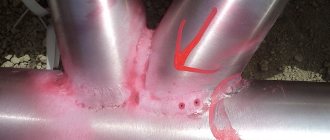
This type of device allows you to determine discontinuities and cracks on the surface of various structures and parts that appeared both during manufacturing and during operation. The essence of the method is to artificially increase the color and light contrast of the defect, due to which the damaged area becomes visible to the naked eye. A special liquid indicator (substances called penetrants) is applied to the surface of the object under study, which, under the influence of capillarity forces, penetrates cracks and pores, filling them. When increasing color contrast (color method), a mixture of kerosene, turpentine, benzene, and coloring components is used as a penetrant. When artificially increasing light contrast (luminescent method), compositions based on noriol, kerosene and other phosphors are used as indicators. After treating the surface with an indicator, the excess is removed, and a developer is applied to the area under study - a fine white powder, which can be talc, magnesium oxide, etc. The developer adsorbs the overtransmitter from the crack or pore, thereby highlighting the contours of the defect. When exposed to ultraviolet radiation, the contours of the crack are brightly illuminated.
Magnetic particle inspection method (magnetic particle flaw detection)
As the name suggests, magnetic particle testing is performed using magnetic powder. There are two methods of magnetic particle testing: dry and wet.
In the case of dry magnetic particle flaw detection, dry magnetic powder (iron filings, scale, etc.) is applied to the surface of the welded joint. In the case of wet magnetic particle flaw detection, magnetic material is applied in the form of suspensions of magnetic powder with kerosene, oil, and soap solution.
Under the influence of electromagnetic stray fields, powder particles move evenly over the surface of the welded joint. Above the weld defects, magnetic powder accumulates in the form of rollers. Based on the shape and size of these rollers, one can judge the shape and size of the defect found.
Magnetic particle testing technology
The magnetic particle flaw detection method includes the following technological operations:
1. Preparing the surface of the welded joint for inspection. Surfaces must be cleaned of dirt, scale, welding spatter, sagging and slag after welding. 2. Preparation of the suspension, which consists of dynamic mixing of the magnetic powder with the transported liquid 3. Magnetization of the controlled product 4. Applying the suspension or magnetic powder to the controlled surface 5. Inspection of the controlled surface of the welded joint and identification of areas where powder deposits are present 6. Demagnetization of the welded joint .
The effectiveness of magnetic particle flaw detection
The magnetic particle flaw detection method has good sensitivity to thin and minute weld cracks. It is easy to implement, gives clear results, and does not take time.
The sensitivity of the magnetic particle method may vary in each individual case. This depends on the following reasons:
1. The size of the powder particles and the method of its application 2. The magnetic field voltage acting on the welded joint 3. The type of current used (alternating or direct) 4. The shape and size of the defect, the depth of its location, as well as how the defect oriented in space. 5. On the method and direction of magnetization of the connection 6. On the quality and shape of the controlled surface
Using magnetic testing methods, planar defects are best detected: welding cracks, lack of fusion and lack of penetration, if their largest dimension is oriented at a right angle (or close to a right angle) relative to the direction of the magnetic flux.
Round-shaped defects (pores, cavities, non-metallic inclusions) may not create sufficient diffuse flow and are the worst to detect during inspection.
Flaw detectors for magnetic particle testing
Flaw detectors for this testing method include current sources, devices for supplying current to the test surface, devices for magnetizing the surface (solenoids, electromagnets), devices for applying magnetic powder or suspension to the surface being tested, and current (or magnetic field strength) meters.
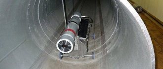
Magnetic particle flaw detectors are divided into stationary, mobile and portable. Stationary flaw detectors are widely used in factories and other enterprises with large-scale production of various products. Among them are such models as UMDE-2500, KhMD-10P, MD-5. Such equipment allows you to control the quality of welded joints of various shapes. They are capable of providing high inspection productivity - from several tens to several hundred products per hour.
We advise you to study - Wind power plants
Common, mass-produced models of portable and mobile flaw detectors are PMD-70 and MD-50P. Portable flaw detector for magnetic testing PMD-70 is widely used for testing welded joints in the field. A mobile flaw detector model MD-50P is most often used to inspect massive large-sized welded joints in sections.
Video: magnetic particle flaw detection using luminescent concentrates
Magnetic particle testing methods
- Residual magnetization method (RMM). The main area of application is hard magnetic materials with a coercive force from 9.5 to 10.0 A/cm. By coercive force we mean a value identical to the magnetic field strength sufficient to change the magnetic induction to zero (from the residual induction). Magnetic particle testing using the residual magnetization method begins with the magnetization of the object. Next, the powder or diluted suspension is applied. After the indicator pattern is formed, the surface is inspected and, if necessary, a defectogram is made (for example, using a photo). SON involves passing current in short-term pulses (only 0.0015–2 s). Local overheating of the metal during magnetization does not threaten. The suspension can be applied by watering the surface or immersing it in a bath. Inspection and decoding are easier because the object can be placed in a more convenient position. In general, this is a more versatile and productive way of conducting control.
- Attached field method (AFM). First, indicator powder or liquid is applied before magnetization begins or directly during the process, under the influence of which an indicator trace is formed. Inspection is carried out after and/or during magnetization and drainage of the suspension. Magnetic particle testing using the applied field method is effective for soft magnetic materials, which are characterized by low coercive force (within 10 A/cm). They are generally available for magnetization and demagnetization in a weak magnetic field. However, in a number of cases, SPP is also used for objects made of hard magnetic materials. For example, if the task is to detect subsurface defects at a depth of 0.01–2 mm. Or in the presence of a non-removable non-magnetic coating with a thickness reaching 40–50 microns or more. SPP is also preferred for large-sized objects, when the power of the flaw detector does not allow them to be magnetized to the level required for the residual stress method.
- dry. Powder from metal filings is applied “as is”, without adding any solutions, etc. Powders are made from carefully sifted and crushed iron scale, magnetite, etc. For better visibility, materials can be white, red or yellow. The dry magnetic particle inspection method is suitable for surface and subsurface defects. Magnetization is carried out with direct or alternating current 300–600A using U-shaped electromagnets. To apply indicators, it is convenient to use rubber bulbs, spray guns, moving sieves and other devices;
- wet. Powder particles are suspended in water, liquid soap, kerosene or a special concentrate. It can be applied by brush, dipping, pouring, etc. The wet method is effective for finding surface discontinuities.
Sensitivity of the technique
To apply the technique, the initial test sample must have a relative magnetic permeability of at least 40. In general, the sensitivity of the technique is influenced by the following factors:
Magnetizing field strength;
Method of applying a dry or wet indicator to a sample;
Electromagnetic properties of the material used for testing;
Location of defects relative to induction lines;
Sample magnetization ability;
Smoothness of the tested surface (the lower it is, the more accurate the study);
Type of electric current that forms a magnetic field;
Research conditions (when using a wet indicator, the degree of accuracy is lower);
A method for fixing an indicator pattern over discontinuities.
Technically, three grades of sensitivity are defined:
A - for defects larger than 2.5 microns and their depth of 25 microns;
B - 10 and 100 microns;
B - 25 and 25 respectively.
To conduct magnetic particle testing of welds, the length of the uneven surface must be at least 0.5 mm; studies are not carried out on smaller defective areas.
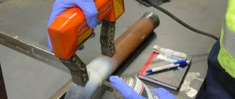
Application of a magnetic indicator
Indicator material is applied to the previously prepared and magnetized surface. It allows you to identify defects in a part under the influence of an electromagnetic field. It has already been said that powders can be used in this capacity, but some models also work with suspensions
In both cases, before work, it is important to consider the optimal conditions for using the device. For example, the magnetic flaw detector “MD-6” is recommended for use at temperatures from -40 to 50 ° C and at air humidity up to 98%
If conditions meet the operating requirements, then application of the indicator can begin. The powder is applied over the entire area, so that a small coverage of areas not intended for research is also provided. This will allow you to get a more accurate picture of the defect. The suspension is applied by jet using a hose or aerosol. There are also methods for immersing a part in a container with a magnetic indicator mixture. Then you can proceed directly to troubleshooting the product.
Strengths and weaknesses of magnetic particle testing
- Detection of a wide variety of surface and subsurface defects. The method is used to search for grinding, fatigue, stamping, forging, hardening, deformation, etching cracks, hairlines, as well as sunsets, flakes, delaminations, and tears. In welds, MPD is capable of detecting undercuts, lack of penetration, cracks, and the presence of oxide, slag and flux inclusions.
- High sensitivity. The magnetic particle testing method is effective for detecting invisible and weakly visible surface defects with the following parameters: opening - from 0.001 mm, depth - from 0.01 mm and length - from 0.5 mm.
- Possibility of carrying out on objects coated with non-magnetic material (paint and varnish materials, zinc, copper, cadmium, etc.). True, provided that their total thickness is in the range of 40–50 microns;
- Harmlessness. The advantage over the capillary method is that MTD does not require “dirty” indicator liquids - with a smell and a strong coloring effect. The operator's health is not in danger. The facility is clean. There is no need to install additional ventilation hoods in the room.
- the range of possible applications is limited to ferromagnetic alloys. MTD cannot cope if the material is characterized by significant magnetic inhomogeneity. Welds - if they are made using non-magnetic electrodes - are also unsuitable for this method;
- access to the facility is critical for the full implementation of all procedures;
- detectability of defects may decrease. This depends on the parameters of the discontinuities themselves. Thus, MTD is not always able to detect defects whose orientation plane forms an angle of less than 30 degrees - relative to the surface under study or the direction of the magnetic field. Sensitivity also decreases in areas with a roughness of Ra˃10 µm. Normal magnetic particle testing is also hampered by poor cleaning (or lack thereof) of soot, corrosion and slag. Yes: identifying subsurface discontinuities is possible, but one must understand that this task is solved much more effectively by ultrasonic testing and x-rays;
- decryption capabilities are very modest. In essence, MPD is an “indicative” type of NC that allows you to see, rather than measure, defects. It is not intended to determine length, depth, width, or reveal discontinuities.
Sensitivity levels
We mentioned sensitivity above. Let's take a closer look at this topic because understanding the whole point will allow you to better understand the topic.
So, according to GOST No. 21105-87, we know that there are only three levels of sensitivity. Each level has its own letter (level A, B, C) and they all depend on the size of the defects.
Level A is the highest, sensitivity is greatest. It is possible to detect defects as small as 2.5 micrometers. Below you can see a more detailed table with information about other sensitivity levels.
You can see that the table contains a column about the maximum permissible roughness. The thing is that magnetic particle flaw detection of welded joints and the success of its implementation largely depend on the surface roughness parameter of the part. If the roughness exceeds the permissible values, the control will be less objective and accurate. But this problem can be partially corrected if you use coarse powder. It must be applied dry. Then it will be possible to detect deep defects with increased surface roughness of the part.
The essence of magnetic flaw detection, its methods
Magnetic flaw detection is one of the methods of non-destructive welding testing. The essence of magnetic methods for testing welded joints is to identify scattered magnetic fluxes that appear in magnetized products if they contain various defects. Magnetized materials can be iron, nickel, cobalt and some alloys based on them.
Magnetization of a product can be achieved if, by passing current through it, a magnetic or electromagnetic field is created around the product. The simplest way to obtain a magnetic flux is to pass a current with a density of 15-20 A/mm through the turns of a welding wire wound in turns around the product. The number of turns is usually 3-6. It is recommended to use direct current to magnetize the connection.
The principle of identifying a defect in a weld is as follows. The magnetic flux, passing through the welded joint and encountering a defect on its way, begins to bypass it due to the fact that the magnetic permeability of the defect is significantly lower than the magnetic permeability of the base metal, and the electric current, as is known, follows the path of least resistance.
As a result of this, part of the magnetic flux lines is displaced by the defect to the surface, forming a local scattered magnetic flux, see figure:
We advise you to study - Linear fluorescent lamps
Magnetic leakage fluxes can be recorded in different ways. According to the recording method, magnetic testing methods are divided into magnetic particle testing method (magnetic particle flaw detection), magnetographic testing method and induction testing method.
Content
- The essence of magnetic flaw detection, its methods
- Magnetic particle inspection method (magnetic particle flaw detection)
- Magnetic particle testing technology
- The effectiveness of magnetic particle flaw detection
- Flaw detectors for magnetic particle testing
- Video: magnetic particle flaw detection using luminescent concentrates
- Magnetographic method for monitoring welded joints
- Magnetographic inspection technology
- Efficiency of magnetic testing
- Magnetographic flaw detector and magnetic tape
Physical basis of magnetic flaw detection
Magnetic testing methods are based on the detection of magnetic leakage fluxes that arise in the presence of defects in magnetized welded joints made of ferromagnetic materials. Magnetic flux F passing through a surface located perpendicular to the lines of force of a uniform magnetic field is equal to the product of magnetic induction B and the area of this surface.
The ability of a metal to be magnetized is characterized by absolute magnetic permeability. The ratio of the absolute magnetic permeability of a material to the magnetic constant is called relative magnetic permeability and is denoted μ. This dimensionless quantity shows how many times the strength of the resulting field in a magnetized medium is greater than the field strength created by a current of the same strength in a vacuum.
Depending on the value of µ, all metals are divided into three groups:
- diamagnetic (copper, zinc, silver, etc.), in which μ is several millionths or thousandths less than one;
- paramagnetic (manganese, platinum, aluminum, etc.), in which μ is several millionths or thousandths greater than unity;
- ferromagnetic (iron, nickel, cobalt and gadolinium, as well as some metal alloys), in which μ reaches tens of thousands.
Magnetic testing methods can only be used for parts made of ferromagnetic materials. The ferromagnetic properties of metals are due to the presence of internal molecular currents, created mainly due to the rotation of electrons around their own axis. Within small volumes (10-8... 10-3 cm3) of elementary regions (so-called domains), the magnetic fields of molecular currents form the resulting domain field.
If there is no external magnetic field, then the magnetic fields of the domains, which are directed arbitrarily, compensate each other. The total field of the domains in this case is zero, and the part turns out to be demagnetized (Fig. 32, a).
Rice. 32. Orientation of domains in ferromagnetic materials: a - demagnetized; b - magnetized until saturation induction; c - with residual magnetization
If an external magnetic field acts on a metal, then under its influence the fields of individual domains are set in the direction of the external field simultaneously with a change in the boundaries between the domains. As a result, a common magnetic field of the domains is formed, and the metal becomes magnetized (Fig. 32, b). During magnetization, the magnetic field of the domains in the controlled metal is superimposed on the external magnetic field.
The magnetic flux, spreading through the welded joint and encountering a defect on its way, goes around it, since the magnetic permeability of the defect is significantly (about 1,000 times) lower than the magnetic permeability of the base metal. As a result, part of the magnetic field lines is displaced by the defect to the surface, and a local magnetic leakage flux is formed (Fig. 33). Defects that cause disturbance in the distribution of magnetic field lines without the formation of a local leakage flux cannot be detected by magnetic flaw detection methods.
The disturbance of the magnetic flux is stronger, the larger the obstacle the defect represents. So, if a defect is located along the direction of the field lines, then the disturbance of the magnetic flux is small, while a similar defect located perpendicularly or obliquely to the direction of the magnetic flux creates a significant leakage flux.
Rice. 33. Distribution of magnetic flux Ф over sections of welds without defects (a) and with a defect (b)
Depending on the method of recording the magnetic leakage flux, the following magnetic testing methods are distinguished: magnetic particle, magnetographic, fluxgate and magnetic semiconductor. For flaw detection of welds, mainly the first three methods are used, in which magnetic leakage fluxes are detected, respectively, using magnetic powder, recorded on magnetic film and detected by a fluxgate converter.
general information
Magnetic particle flaw detection of welded joints (also known as magnetic particle flaw detection) is a quality control method, the essence of which is to detect magnetic fields around a defect using ferrimagnetic substances.
If a part has any defect, then a magnetic field will certainly form above it, which will be distorted. The part is initially magnetized and the magnetic lines simply bend around the defects encountered along the way. The result is a distortion of the magnetic field. In addition, magnetic poles can form along the edges of the workpiece, which in turn create local magnetic fields. The figure below shows a schematic representation of the magnetic field.
All information about changes in the magnetic field is recorded using a flaw detector. The larger the defect, the greater the dispersion, and therefore the probability of detecting a defect. And if the magnetic lines are located at right angles to the defect, then the likelihood of its detection increases.
Where to buy a magnetic particle flaw detector
| Research and production. Founded in 1989, certified according to the international standard ISO 9001:2015. For manual inspection, you can buy a universal magnetic particle flaw detector MDM-2, modular MD-M, pulse MD-I, and also equipped with two magnetization coils DUCAT-300 from the Kropus Research and Production Center. In addition, the line includes solutions for automated control in production - SM-20, SM-20N and SM-30. The center’s powerful technical base allows us to develop individual solutions for specific tasks. Contacts of the production site of the SPC "Kropus" in Noginsk, [email protected] |
| Research and production. As the official distributor of Magnaflux GmbH, the entire line of mobile devices ITW Tiede GmbH is presented here - Ferrotest 10, 20, 40, 60, 80, 100, GWH 15, 30, 40, Isotest 60E, 100E, etc. You can also select and buy here and a stationary magnetic particle flaw detector: both universal (for example, Ferroflux 1000 and Universal 600 WE) and specialized - for testing springs, crankshafts, couplings, small and large diameter pipes, railway wheel pairs, etc. AVEK also has its own development - the MAG-Inspect Universal installation. Contacts of the central office in Yekaterinburg: +7 (343) 217-63-84, |
| Scientific and industrial. The main product for the MPD method is the stationary installation MDS-09, developed in-house for testing products up to 900 mm long, up to 210 mm in diameter and weighing up to 100 kg. The production base of the enterprise is located in Balashikha. You can contact NPK "LUCH" by phone +7 (498) 520-77-99 or by mail |
Method - magnetic flaw detection
Magnetic flaw detection methods can be used to detect iron-oxide deposits in pipes made of austenitic steels. The use of such methods for inspecting pipes made of magnetic materials is practically excluded due to the need to have a magnetizing current of hundreds of amperes, which cannot be obtained with a battery-powered flaw detector.
Magnetic flaw detection methods can be used to detect iron oxide deposits in austenitic pipes. The use of these methods for testing pipes made of magnetic materials is practically eliminated due to the need for a magnetizing current of hundreds of amperes, which cannot be obtained with battery power.
Methods of magnetic flaw detection of welded joints are based on the magnetization of products and the formation of stray fields in welds with defects. There are two methods of magnetic flaw detection: magnetic powder and induction. The magnetic powder method is that if there is a defect in the welded joint, then the magnetic lines of force, trying to bypass it, reach the surface of the seam, and the defect is detected by the accumulation of magnetic powder. This method reveals defects located at a depth of up to 5 mm, with a width of more than 0 03 mm. The induction method allows you to identify defects located at a depth of up to 15 mm. The induction method is used to control butt welded joints up to 30 mm thick.
Methods of magnetic flaw detection of welded joints are based on the magnetization of products and the formation of stray fields in welds with defects.
| The presence of stray fields when the defect is oriented perpendicular to the magnetic field lines ( a and along the magnetic field lines ( b. | Diagram of distortion of the magnetic field lines at the point of metal discontinuity. |
Inspection using magnetic flaw detection methods involves creating a magnetic stray field over a defect and its subsequent detection.
The corrosion state is monitored using magnetic flaw detection, radiographic, ultrasonic listening or television cameras passed inside the pipe. The study of stresses and deformations is carried out by mechanical devices launched through the pipeline at the end of construction, by the strain gauge method, etc. To detect leaks, visual inspection is used during detours or overflights of the route, gas analytical, acoustic emission and other methods.
Magnetic flaw detection methods are based on the registration of the latter.
We advise you to study - How automatic transfer switching devices (ATS) work in electrical networks
Each connecting rod bolt is subjected to testing using magnetic flaw detection methods to identify external defects and ultrasound to identify internal defects.
Ultrasonic, color and magnetic flaw detection methods are used to carry out inspections of equipment, machines and communications; in some cases, the audit is carried out during the overhaul period, which makes it possible to reduce equipment downtime during the audit to zero.
| Halogen leak detector. |
Depending on the method of detecting magnetic leakage fluxes, there are two main methods of magnetic flaw detection: magnetic powder and induction. With each method, the controlled area is magnetized.
To check the suspension devices of lifting machines with a belt traction element, it is advisable to use magnetic flaw detection methods. For this purpose, the tested parts are magnetized by directly passing an electric current through them or indirectly by winding several turns of insulated copper wire around the tested part and passing a current of the required magnitude through them. After this, small parts are immersed directly in oil, in which magnetic particles are suspended. Large parts are sprayed with a similar solution or a layer of magnetic powder and oil is applied to them.
| Formation of magnetic flux leakage fields. |
Depending on the method of recording (fixing) magnetic stray fields, magnetic particle, induction and magnetographic methods of magnetic flaw detection are distinguished.
Induction control method
Unlike magnetic particle and magnetographic methods, which are based on the usual detection of scattered magnetic fluxes in the defect zone, the induction method is based on the use of scattered magnetic fluxes using special induction coils.
To search for defects, induction flaw detectors have coils that are placed on the welded joint or placed on its surface. In this case, the induction coil is connected to some recording device (telephone, signal lamp or galvanometer).
The welded joint is magnetized and the coils are moved along it. In some cases, on the contrary, the product being tested is pulled through the coils. When the coil crosses an area with a defect, then in its turns, due to a change in the magnetic flux in this area, an electromotive force of induction appears. The resulting induced current from the coil is supplied to the recording device directly or through an amplifier. By the sound, the ignition of a signal lamp, or the deflection of the galvanometer needle, it is determined that there is a defect in this place.
The disadvantage of the induction testing method is its very low sensitivity to the smallest defects located on the surface.
Additional
Magnetization options
Most magnetization options are applied to parts of basic geometric shapes, and they get their name partly from these shapes:
Circular magnetization creates an even field inside the element under study, with no poles appearing at the edges.
Longitudinal, or, in other words, polar, creates a field directed along the field, with a plus at one end and a minus at the other.
Combined - in different perpendicular directions causes the emergence of multidirectional fields.
Rotating field magnetization is often used in industrial plants to evaluate the quality of a weld.
Types of electric current used for magnetization:
Constant, to form uniform induction;
Variable - more often used for simple, low-sensitivity testing techniques;
Pulse - its features are more similar to constant.
Device structure
The basis of the segment of magnetic thickness gauges and flaw detectors are hand-held devices equipped with magnetized working parts - usually in the form of pliers. Externally, these are small devices, the filling of which is an electromagnet that regulates the poles of the wave action. The middle class allows you to work with magnetic permeability, the coefficient of which is higher than 40. The body is equipped with an ergonomic handle, thanks to which the device can be used in hard-to-reach places. To supply electric current, the devices are also provided with a cable connected either to a generating station (if work is carried out outdoors) or to a 220 V household power supply. More complex non-destructive testing equipment has a stationary base connected to a computer. Such diagnostic tools are more often used to check the quality of manufactured parts in production. They perform quality control, recording the smallest deviations from standard indicators.