Design of axial tools
TO
category:
Turning
Design of axial tools
Next: Milling cutter design
Drills with a diameter d = 0.3-20 mm with a cylindrical shank are made solid from high-speed steel or welded (with d>8 mm); in the latter case, the shank is made of steel 45, and the cutting part is made of high-speed steel.
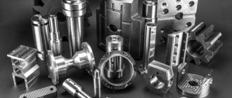
Rice. 1. Cutter design with mechanical fastening of carbide cutting insert
Drills with a conical shank with a diameter d == 6-f-80 mm are made welded (the cutting part is made of high-speed steel, the shank is made of style 45).
Carbide drills with a diameter d = = 14-6.5 mm with a cylindrical shank are manufactured as composite drills (the working part is pressed into a steel shank). These drills usually have reduced accuracy due to the mismatch between the axes of the working part and the shank. Solid drills with a diameter of 1 - 12 mm, which are usually made from cylindrical carbide rods, the chip grooves on which are ground with diamond shaped wheels, have higher accuracy.
The working part of a carbide drill can be soldered to a cylindrical and conical (Fig. 10.6, e) shank; in the first case, the drill diameter is d = 3-r-12 mm, in the second - rf = 6-^-T2 mm. Shanks made of steel 45 and steel 40X are soldered with L68 alloy with a solder thickness of no more than 0.1-0.15 mm.
The main dimensions of drills and technical requirements for their quality, accuracy, hardness and surface roughness are established by the standard.
The designs of the main types of countersinks are shown in Fig. 3. High-speed countersinks with a diameter of D=10-b40 mm with a conical shank (Fig. 10.7, a) are made composite (welded); The shank of these countersinks is made of structural steel.
For precise centering on the mandrel, the base hole of such countersinks is made conical (with a taper of 1:30).
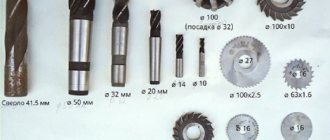
Rice. 2. Twist drill designs
Composite countersinks (with soldered carbide plates) with a shank are used for processing holes with a diameter of 14-50 mm, and mounted compound countersinks with soldered carbide plates are used for processing holes with a diameter of 32-80 mm. The body of the mounted countersink is made of steel 9ХС or steel Р6М5.
Mounted countersinks of a prefabricated design with insert knives made of high-speed steel or hard alloy are used for countersinking holes with a diameter of 50-100 mm, and tail countersinks with insert knives equipped with carbide plates are used for processing holes with a diameter of 30-50 mm.
A prefabricated countersink consists of a body in which the knife is secured with a wedge. The knife is installed in the body using longitudinal corrugations, which are cut on the supporting surfaces of the groove and knife. Depending on the size of the countersink, the pitch P of the corrugations is 0.75; 1 and 1.5 mm. After dulling, the knives are moved from the center by one or two groove steps and secured with wedges. Then the countersink is ground along the strips, maintaining the required diameter, and the edge is sharpened. In this way, you can restore the original diameter of the countersink or grind it to the required size. Typically, a prefabricated countersink has several sets of spare knives.
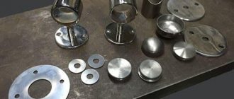
Rice. 3. Countersink designs
Rice. 4. Prefabricated countersink
Countersinks are used to form cylindrical stepped, conical and end bearing surfaces for fasteners. The main types of countersinks are shown in Fig. 5. Using a pin with diameter d, the countersink is centered relative to the previously machined hole.
Countersinks with a replaceable guide pin have the following advantages: it makes it easier to sharpen the end teeth, since it is done with the pin removed; the number of regrinds increases; One countersink can be used for different pilot hole diameters in the workpiece.
To process surfaces for conical screw heads and center holes, conical countersinks made of high-speed steel are used. These countersinks have apex angles of 2<р=60; 75; 90 and 120° and diameter D = 8 80 mm..
Reamers are used to improve the accuracy of the shape and size of holes and reduce the roughness of the machined surface. According to the method of application, reamers are divided into manual and machine ones, according to the type of hole processed - into cylindrical and conical, according to the method of fastening - into tail and attachment ones, according to the design feature - into solid, composite, prefabricated and expanding, according to the operation performed - into roughing and finishing .
Structural elements of cylindrical reamers are shown in Fig. 6. The tail reamer consists of a working part, a neck and a shank. In turn, the working part has a cutting part with a guide cone and a calibrating part with a reverse cone. The attachment reamer has its hole, the end keyway, its working part consists of the same parts as the working part of the tail reamer. Cylindrical reamers have 6, 8 or 12 teeth of a single-angle shape, that is, the cavity between the teeth is formed by one angle. To avoid cutting the unfolded hole, the angular step t is made uneven.
Rice. 6. Countersink designs
Depending on the type of reamer, diameter and operating conditions, the composition, design and dimensions of its main parts change.
Machine high-speed reamers with a diameter of 2-16 mm are made with a cylindrical shank, and for larger diameters - with a conical shank.
When reaming using conductor bushings, reamers with a working part length increased by 3-5 times are used.
Mounted machine reamers with a diameter of 25-50 mm are made entirely of high-speed steel.
Rice. 7. Cylindrical mounted countersink: 1 - main cutting edge, 2 - main rear surface, 3 - additional rear surface, 4 - auxiliary cutting edge, 5 - guide strip, 5 and 7 - surfaces forming the back of the screw tooth, 8 - front surface screw tooth, 9 - front surface of the end tooth
Rice. 8. Structural elements of cylindrical reamers: a - tail machine, b - machine nozzle, c - manual
Manual reamers have a cylindrical shank, ending in a square, with the help of which the reamer is rotated with a knob during operation; the working part of such reamers does not have a guide cone, and the cutting part is made with a small angle f = 1-2° and a large length, which ensures good centering of the reamer.
Manual reamers with a diameter of 3-50 mm are usually made from steel grades U12A, 9ХС and less often from high-speed steel.
Tail and attachment reamers with a diameter of 10-50 mm can have soldered carbide plates.
Rice. 9. Designs of prefabricated reamers
For reamers with a diameter of 3-12 mm, the working part, made entirely of hard alloy, is soldered to the shank. Reamers with a diameter of up to 3 mm with a cylindrical shank can be made entirely of carbide.
The designs of prefabricated reamers are shown in Fig. 9. The reamer allows for precise adjustment of the knives, which are moved using a nut simultaneously along the inclined corrugations of the body, which ensures their identical position relative to the reamer axis. When the knives are pulled out of the body, the diameter of the reamer decreases. The knives are secured with an eccentric, which is cored in the body.
After assembling in the body, adjusting and securing the knives, the reamer is ground to obtain an accurate diameter and the cutting edges are sharpened. This sequence is common to all prefabricated scans. Prefabricated reamers with a diameter of over 40 mm are made with high-speed knives, and with diameters over 50 mm - with knives equipped with carbide plates.
A manual expansion reamer is designed for reaming through holes with different diameter tolerances. Such reamers with a diameter of 6-50 mm are used in individual production and for repair work. A deep hole is made in the reamer body and thin grooves are cut to allow deformation during adjustment. When the screw is screwed in, the ball expands the body and the diameter d increases. The diameter size is controlled with a micrometer. With this reamer you can ream holes that differ from its nominal size by 0.1-0.5 mm.
A machine expansion reamer equipped with carbide inserts is shown in Fig. 9, f. The working part of the reamer has through thin slits. When screwing the screw, its end opens the reamer and adjusts its diameter. To prevent the screw from turning loose during operation, a compression spring is inserted into the housing, which locks the screw. Machine expansion reamers are made with a diameter of 15-40 mm.
Axial cutting tool
An axial cutting tool is a blade-type machining tool with a rotary main cutting motion and a feed motion along the axis of the main cutting motion.
Axial cutting tools include:
- Drills - necessary for making holes in solid material or increasing the diameter of a hole in an existing one. In turn, drills are divided into:
- monolithic carbide drills. Used for drilling hard-to-cut, hardened metals and alloys.
Main advantages:
- High accuracy
— Minimum runout
— Possibility to obtain holes of class 8 and 9 with minimal roughness
— No additional reaming or countersinking of the hole is required
— Resharpening is possible
— High rigidity of the structure makes it possible to work with high feeds without breaking the drill
- Drills with replaceable inserts. This is a tool with a wide range of diameters for machining holes with depths from 2D to 5D. The inner insert, which cuts in the center of the drill at zero speed, is made from a durable alloy and has a reinforced chipbreaker. On the other hand, the external wear plate allows the cutting speed in the peripheral part of the tool to be doubled compared to solid drills. Selecting the correct peripheral insert grade ensures high productivity and long tool life.
- High speed steel drills. They have good performance indicators. They have high strength and durability and are suitable for processing various metals.
- Microdrills - The use of microdrills allows you to reduce the cost of parts that have small diameter holes, as well as increase the productivity of machining. Micro drills allow you to drill holes that could only be made using the electrical discharge method.
- Drills for deep drilling. A hole with a diameter of more than 5 is considered deep. Features of deep drilling: tools not suitable for children, difficult removal of chips, difficult supply of coolant, special equipment required
- A countersink is a tool for increasing the accuracy of the hole shape and increasing the diameter.
- A countersink is a multi-edged tool for processing.
- Counterbore is a multi-blade tool for processing the cylindrical and end sections of a workpiece
- Reamers are a tool for improving hole accuracy, dimensions and reducing surface roughness.
Contact Information:
LLC "KUBit"
Address: 102 Torez Ave. 4, office 2 (opening hours Mon-Fri 9.00-18.00)
Email:
Website:
Plasma cutting of metal
metal plasma cutting services .
in detail »
To estimate the cost and timing of the work, you must send: sketches, sample photos, drawings in any format to the email: [email protected] or click on the banner “calculate the cost of the order” In the letter, be sure to indicate: 1. Number of parts. 2. Material.
The mail is being tracked promptly and a response will be given shortly.
FAQ.
1. Do you have the material?
- The material is varied, steel, from ordinary carbon to alloyed, brass, copper, bronze, textolite, caprolon, ebonite, etc. By agreement, we will find unique grades of steels and alloys.
2. Do you take single orders?
- We take orders from the 1st unit. Minimum order 2000 rub.
3. What are the prices and how much does it cost to make a part?
- Prices range from 300-800 rubles/hour of machine time, depending on the order volume and complexity. A correct assessment can be given after studying the drawing, sketch or provided sample of the product sent by email. For urgency, the extra charge is from 20 to 50%, depending on the volume and degree of urgency.
4. What are the production times?
- Production time is from 2 days depending on the volume of the order.
Example of impeller processing
I would like to illustrate the considered strategies using the example of processing a very complex product - an impeller. Three stages can be distinguished here: preparing the model, rough sampling of cavities and finishing of the blades (Fig. 17).
The complete product is shown in Fig. 17a; A guide surface is created along the lower edges of adjacent blades (shown in black in Fig. 17b), which with its normal will set the orientation of the axis when sampling the inter-blade cavity. The use of such a surface allows the use of a variable (parametric) step, that is, the passes will follow along the generators of this surface. In this case, the tool is brought in and out for each pass outside the cavity. In Fig. 17c shows a single-pass (the variable step of the passes is visible here), and in Fig. 17g - multi-pass cavity processing (carried out if necessary) with setting the tool axis normal to the guide surface. All this is rough processing.
Next, the side surface of the cutter is used to process the impeller blades. In Fig. 17d shows a multi-pass (semi-finish), and in Fig. 17e - single-pass (finishing) processing option.
Another reason to choose 5-axis machining
5-axis continuous strategies are also becoming relevant for toolmakers due to the rapid development of “time compression” technologies, when, for example, silicone casting is used instead of traditional molds to produce a small batch of products. In this formulation of the question, the impeller discussed in this article will be a model for molding into silicone molds and must be made in one copy (a detailed discussion of time compression technologies is beyond the scope of this publication).
5-axis profile strategy
The most common 5-axis continuous strategy among toolmakers is finishing a complex profile. In Fig. Figure 11 shows the machining trajectory of a groove with walls located normal to the surface. Typically, at this stage, 3-axis machining with a ball cutter has already been completed, and the residual radius in the concave corners is usually left for manual or EDM finishing. By using 5-axis end mill profiling, manual reworking can be greatly reduced and shape accuracy can be improved.
An important benefit of PowerMILL is that a wide range of cutting tools can be used for 5-axis toolpaths, including end mills, ball and fillet cutters, tapered cutters, tapered ball cutters and tapered fillet cutters. Typically, other systems are limited to using only ball and end mills, which is not always effective, especially at the roughing stage.
Projection methods for tool axis orientation
The Delcam PowerMILL package, along with the ability to work with the normal to the surface, has special methods for orienting the tool axis, more suitable for tool processing and based on projecting the tool axis to (from) a point (Fig. 12) or to (from) a line (Fig. . 13). As can be seen in Fig. 12, local protrusions on the surface do not cause a sharp change in the direction of the tool axis, which is usually required. Shown here is the "from point" option used for concave sections; for convex sections, the point is set in the body of the product and the tool axis will point towards the point. Orientation to (from) a point is used for surfaces close to spherical, and to (from) a line - for surfaces close to cylindrical.
Drive surface machining
In Fig. Figure 14 shows an example where machining the outer surface with normal axis control will cause overcut of the adjacent surface in the neck area, which is unacceptable. In addition, when processing a spherical area near the axis of the product, the tool must rotate almost along the axis, and this exceeds the maximum angles of the rotary axes or causes a collision of machine components. For this case, it is advisable to create an auxiliary surface (shown in blue), to which the tool axis is set normal, and all surfaces located higher along the tool axis will be processed. PowerMILL can also use a set of auxiliary surfaces; It is desirable that they mate with each other tangentially to prevent a sharp change in the direction of the axis.
The guiding surface principle is a further development of the methods of axis orientation “towards a point (line)/from a point (line)”. We can say that the "from a point" orientation is the case when the guide surface is a sphere, and the "from a line" is a cylinder. In particular, with a torus-shaped guide surface, inscriptions can be applied to molds for the production of automobile tires.
5-axis toolpaths from 3-axis
It is also worth mentioning the possibility of creating 5-axis toolpaths from 3-axis ones created by strategies that do not support 5-axis processing. Thus, PowerMILL has a so-called pencil strategy that automatically searches for concave corners and creates a profile pass along such corners. The resulting trajectory can be used as a template for 5-axis processing (Fig. 15). This is most clearly seen in the example of a ball cutter: first, the trajectory for the top of the tool is calculated (Fig. 15 on the left), then it is shifted by a radius in the direction of the tool axis - thus, a trace of the center of the sphere is obtained; then, to orient the axis, the resulting contour and a point lying above the contour are used (the “from point” method); the tool looks from a point to each point of the contour; at the last step, the contour is shifted back by the radius amount (but in the direction of the new axis) and the processing path is obtained (Fig. 15 on the right). Naturally, all these steps are included in the algorithm, launched by one operation. As a result, a significantly shorter tool is used for machining. In Fig. 16 demonstrates a similar situation, but in volume.
3-axis milling
The simplest type of processing in which the workpiece is fixed in one position. Spindle movement is available in linear X, Y and Z directions.
3-axis milling
3-axis machines are commonly used to machine 2D and 2.5D geometries. With 3-axis machining, it is possible to machine all 6 sides of a part, but each side requires a new fixture installation, which can be expensive (more on this below). When installing one fixture, only one side of the part can be processed.
Each side of the part requires a unique setup.
Many complex and practical shapes can be produced using 3-axis CNC milling, especially when it is in the hands of world-class machining equipment. Three-axis machining is best suited for producing flat milled profiles, drilling and tapped holes on one axis. Undercuts are possible using T-slot and dovetail cutters.
However, sometimes a design part cannot physically be produced on a 3-axis machine, or the feature may be more cost-effective to machine on a 4 or 5-axis machine.
Features not accessible with 3-axis milling include any feature that is at an angle to the XYZ coordinate system, even if the feature itself is planar. There are two types of corner features you can design, and understanding the differences between them is important when designing parts for CNC milling.
CORNER ELEMENT
This is a feature machined at an angle to one of the X, Y, or Z axes. For example, the flat milled surface below is at a 45° angle to the X-axis, such as an A-axis rotation.
The milled element is located at an angle of 45 ° in one plane
COMPOSITE ANGLE
This is an element processed at an angle to two axes. For example, the flat milled surface below is machined at an angle of 45° to the X-axis and at an angle of 30° to the Z-axis.
Both corner and compound corner elements cannot be machined on 3-axis CNC machines.
Milled compound corner element in two planes: 45° X-axis, 30° Z-axis
Side surface treatment
Side surface processing (Swarf Milling) is used to form profile passes when processing ruled surfaces (Fig. 10). When using 5-axis machining, such passes may include undercut machining, which is useful when machining pockets with a wall with a variable slope, such as shallow surfaces in aircraft manufacturing.
If the surface is close to ruled, but is not, then you can use the previous strategy with a deflection angle of 88-89° and a multi-pass option (for comparison: when processing a side surface, the deflection angle is 90°).