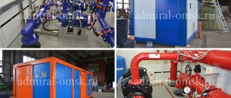
We offer steam ejectors TLV SC/RSC series and Baelz 590 series - we select a suitable solution, configuration, supply products, and carry out commissioning work. Our company employs specialists with an excellent understanding of ejectors and extensive experience in their integration into technological and auxiliary processes.
We have recirculation ejectors to increase the speed/quality of heating and thermal compressors to increase the efficiency of using low-grade steam in enterprises. Experience has shown that the reduction in steam consumption when using a recirculation ejector ranges from 8 to 40%, depending on the technical conditions and the selected circuit design.
Ejectors are used in piping heat exchangers with special (high) requirements for the quality of the heating process, in flash steam recovery systems and in mixing steam at different pressures.
Application:
- Groups of parallel connected heat exchangers.
- Rotating drying drums PM and KDM.
- Shafts on corrugated presses.
- Press plates in plywood production.
- Plates of vulcanization presses in the production of rubber products.
- “Batteries” of several steam-air heaters.
- Digesters (reactors).
- Evaporation columns.
- Calenders.
- Submersible coils, high-speed heaters.
- Heaters in the pharmaceutical industry.
According to their purpose, ejectors are divided into two types:
- Recirculation ejectors - to regulate steam flow and condensate removal in heat exchange processes;
- Thermocompressors - for mixing steam flows with different pressures and recycling flash steam.
Advantages of a recirculation ejector
- there is no need to install condensate traps at the outlet of each consumer - reducing the cost of purchasing and installing condensate traps and their piping, as well as increasing the overall reliability of the system;
- high quality of the heat exchange process - uniform temperature over the entire heat exchange surface, regardless of the configuration of the heat exchanger and the current load;
- precise control over a wide load range;
- higher steam velocity in the heat exchanger - higher heating rate;
- the steam at the ejector outlet is closer to saturation compared to the steam at the control valve outlet - the heat transfer efficiency is higher.
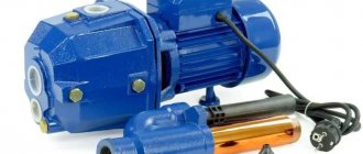
Ejector pumping station
A pumping station with a built-in ejector is a set of equipment originally designed to perform work under certain conditions. The main parameters that are taken into account when choosing are power and performance. The first characteristic means the ability to maintain pressure in the system, as well as the ability to retain a water column and transmit liquid over a distance through a horizontal pipeline.
The second characteristic is productivity. This is the amount of liquid pumped per unit of time. This parameter cannot be greater than the well flow rate. If we are talking about purchasing a pumping station with a built-in ejector, then the technical documentation indicates the general output characteristics. This means that no additional calculations will have to be made.
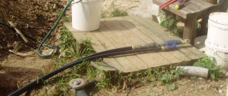
The equipment is connected according to the attached instructions. The hoses are attached using clamps included in the kit. The pipeline requires a threaded connection. The main thing is to provide a place for installation so that rain and frost cannot damage the system. For this, a caisson is made or a separate building is built. The canopy is only suitable for a summer house that is not intended for year-round use.
A pressure gauge is installed as additional equipment for a pumping station with an ejector, if this is not provided by the manufacturer. Thanks to this device, you can control the pressure in the pipeline. Naturally, it is installed at the exit of the station. If the well depth is within 15-40 meters, experts recommend installing a surface pump with a remote ejector.
Connection diagram
The best connection scheme involves connecting the station to the ejector only with a vertical pipe. Otherwise, airing is possible, which leads to a decrease in system performance. If this is not possible, you need to take care of shut-off valves to bleed air as necessary.
The described equipment completely solves the need of house residents for drinking water. Watering the plot, irrigating garden beds, front gardens or gardens is also organized in a similar way. The main condition is to correctly select the system components so that their performance characteristics are in full compliance. Then the system with an ejector will be quite effective, and at the same time inexpensive.
Recirculation ejector - comparison with control valve
The ejector, equipped with a drive, is an adjustable jet pump. The device combines the functions of a control valve and a jet pump. The ejector is installed in the heat exchanger piping instead of the control valve. Let's compare two methods of automatic load control on a heat exchanger: a “classical” system with a control valve at the inlet and a condensate trap at the outlet of the heat exchanger, and a control system with a recirculation ejector.
Rice. 1. Regulation of steam flow by a straight-through control valve, removal of condensate by a condensate trap at the outlet of the heat exchanger.
In Fig. Figure 1 schematically shows a traditional heat exchanger piping system using a control valve at the inlet to the heat exchanger and a condensate trap at the outlet. The steam pressure should push the condensate through the steam trap. At the same time, the efficiency of the heat exchange process significantly depends on whether the condensate will completely and quickly leave the heat exchanger through the condensate trap, including if the control valve at the inlet, responding to the load change, closes so that the pressure behind it drops significantly. As a rule, the more the control valve closes, the worse the heat exchange efficiency, since the rate of condensate removal is significantly reduced and more and more condensate begins to flood the heat exchanger.
Rice. 2. Regulation of steam flow by the ejector and removal of condensate through an intermediate vessel to separate recirculating steam and condensate.
In Fig. Figure 2 shows that the control valve is the ejector itself, which not only regulates the supply of live steam to the heat exchanger, but also sucks in steam from the outlet of the heat exchanger that has not condensed. Thus, part of the steam continuously circulates, constantly blowing through the heat exchanger and preventing condensate from stagnating in the heat exchanger. The temperature of the heat exchange surface in this case is always higher than in systems with a condensate trap at the outlet of the heat exchanger. A condensate trap is not installed at the outlet of the heat exchanger, it should be installed at the outlet of the vessel to separate the steam and condensate leaving the heat exchanger. Condensate is separated from steam not in the small space of the condensate drain and condensate pipeline at the outlet of the heat exchanger, but in the vessel, therefore nothing interferes with the complete removal of condensate.
Figures A and B show examples of piping a digester with a steam jacket according to the traditional scheme ( A)
with a control valve at the inlet and a condensate trap at the outlet, as well as according to scheme (
B)
with a recirculation ejector.
In example B,
the temperature of the heat exchange surface is the same at the top and bottom, and is usually higher than with a condensate trap, since the condensate film is always thinner.
In addition, the steam at the outlet of the control valve in example A
may be overheated after throttling, that is, the heat transfer coefficient in this case is lower. The ejector mixes two steam streams and the steam at the ejector outlet is always closer to the saturation state when throttling than with a conventional control valve.
Why are ejectors needed and what are they?
For many homeowners, organizing an autonomous water supply becomes a problem due to the large depth of the pit.
Already from the eight-meter mark problems begin. For pumping stations with ejectors, the same possibilities as for high-capacity pumps. The use of deep sources requires the use of powerful submersible pumps, which are expensive.
What are ejectors used for? So as not to waste money on expensive models. The use of inexpensive pumping stations with ejectors can solve the problem with the same efficiency. At the same time, modernization costs are minimal. Moreover, you can improve the system using a local method or purchase a complex that was originally designed for this.
Principle of operation
All ejectors for pumping stations operate according to the same scheme. The basis is Bernoulli's principle. In accordance with it, if the flow is accelerated, then a rarefaction zone is formed in the zone in front of the acceleration point. The pressure in it is lower, which causes a retracting effect. If you add it to the flow generated by the pumping station, then the result of such modernization is an increase in productivity.
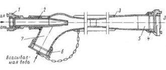
Device
Whatever type of device is considered, the ejector pump consists of:
- suction compartment;
- mixing cavity;
- diffuser;
- tapering pipe.
The principle of operation is that liquid is ejected from the nozzle (pipe) at high speed. The outflow of water provokes the appearance of low pressure inside the working chamber, which draws in liquid. The cycle is repeated continuously, which allows maintaining constant pressure in the pipeline.
Choosing an installation location
For correct operation of the equipment, the pressure switch must be connected to the pump in such a way as to avoid the influence of turbulence and sudden pressure changes when the pumping equipment is turned on and during its operation. The best place for this is in the immediate vicinity of the hydraulic accumulator.
In the classic scheme for connecting a pressure switch to a deep-water pump for an autonomous water supply, the following equipment is installed in front of the relay:
- pumping unit,
- check valve,
- pipeline,
- flow shut-off valve,
- drainage to the sewer,
- filter for preliminary (coarse) cleaning.
When using many modern models of surface-type pumping units, installing a water pressure switch for a pump can be much simpler: block installation is carried out when the relay is installed together with the pump. The pumping unit has a special fitting, so the user does not need to independently search for the most suitable installation location. The check valve and filters for water purification in such models are often built-in.
Connecting the pressure switch to a submersible pump can also be done by placing the hydraulic accumulator in the caisson and even in the well itself, since waterproof design of the control equipment is often required and the operating conditions of the pressure switch may allow its location in such places.
The connection diagram for a pressure switch and a pumping station with a surface pump differs slightly from the diagram with a submersible unit in the sequence of arrangement of some elements
Obviously, the choice of installation method and location depends on the design of the equipment; usually all recommendations in this regard are indicated by the manufacturer in the accompanying documentation.
Features and types of design
There are two types of ejector type pump:
- with external ejector location;
- with internal (built-in) ejector location.
The choice of one or another type of ejector layout is determined by the requirements for pumping equipment. To suck air from different containers, another type of such units is used - an air ejector. It has a slightly different operating principle. In our article we will study devices to facilitate pumping water.
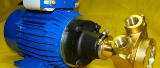
Internal ejector
Pumping equipment with a built-in ejector has more compact dimensions. In addition, the creation of liquid pressure and its intake for recirculation occurs inside the pumping equipment
Pumping equipment with a built-in ejector has more compact dimensions. In addition, the creation of liquid pressure and its intake for recirculation occurs inside the pumping equipment. This pump uses a more powerful motor that can recirculate liquid.
The advantages of this design solution:
- the unit is not sensitive to heavy impurities in water (silt and sand);
- the water entering the equipment does not need to be filtered;
- the device is suitable for lifting water from a depth of no more than 8 m;
- Such pumping equipment provides sufficient liquid pressure for domestic needs.
Among the disadvantages it is worth noting the following:
- this pump makes a lot of noise during operation;
- To install such a unit, it is better to choose a place away from the house and build a special room.
External ejector
To install the ejector externally next to the pumping equipment, it is necessary to equip a tank into which to fill with water
To install the ejector externally next to the pumping equipment, it is necessary to equip a tank into which water should be collected. In this container the working pressure and the necessary vacuum will be created to facilitate the functioning of the pumping equipment. The ejector device itself is connected to that part of the pipeline that is immersed in the well. In this regard, there are restrictions on the diameter of the pipeline.
Advantages of a remote ejector:
- thanks to this design, it is possible to lift water from a significant depth (up to 50 m);
- it is possible to reduce the noise from the operation of pumping equipment;
- such a structure can be placed directly in the basement of the house;
- without reducing the efficiency of the pumping station, the ejector can be placed at a distance of 20-40 m from the well;
- Due to the fact that all the necessary equipment is in one place, it is easier to carry out repair and commissioning work, which contributes to a longer service life of the entire system.
Disadvantages of the external location of the ejector device:
- system performance is reduced by 30-35 percent;
- restrictions in the choice of pipeline diameter.
| Steam jet pumps |
| Steam-water ejectors |
| Steam-oil ejectors. |
| Vortex pumps |
| Diffusion high vacuum pumps |
| High vacuum units |
| All pages |
Page 4 of 8
Steam-water ejectors (Fig. 323) were received. The most widespread and have pumping speeds of hundreds of thousands of liters per second. For example, one steam-water ejector pump NEV-100X0.5 of average performance with a pumping speed of 32,000 l/s at a pressure of 0.5 mm Hg. Art. replaces 270 mechanical pumps VN-6:
The small-sized two-stage pump NEV-0.2X20 works according to! diagram shown in Fig. 324. The vapor-gas mixture from stage II of the pump enters the mixing condenser, where water is supplied from water-jet pumps. Pump capacity 0.5 kg/h at a pressure of 20 mm Hg. Art., maximum pressure 10 mm Hg. Art. Steam consumption 12 kg/h at a pressure of 2.6 atm water consumption 0.35 m3; h at a pressure of 1 atm. Overall dimensions: plan area 500×445 mm, height 1.025 m.
The NEV-2X20 pump has a capacity of 3 kg/h of dry air at a pressure of 20 mm Hg. Art.; works according to the same scheme as NEV-0.2X20. Pumps NEV-0.2Х20 and NEV-2Х20 are small-sized. They can be used in chemical industries where a pressure of 10-20 mm Hg is required. Art., as well as for oil-free pumping systems. The characteristics of the pumps are given in table. 58.
The NEV-100X1 five-stage pump with a first stage without a condenser creates a maximum pressure of 0.5-1 mm Hg. Art. If you install two, three or more stages without condensation, you can obtain maximum pressures of 10-1-10-2 mm Hg. Art. The use of stages without intermediate condensers significantly increases the steam consumption per unit of pumped gas. The diagram of the NEV-100X1 pump is shown in Fig. 325.
Rice. 323. Scheme of a two-stage steam-water ejector pump:
I - first stage; 2 - second stage; 3 - mixing capacitor; 4 - drain pipe 6a; 5 — exhaust pipe; 6 - barometric well
Rice. 324. Scheme of the NEV-0.2X20 pump:
1, 10, 13 - steam valves; 2 — second ejector stage; 3,4 - capacitors; 5 - drain pipe; 6 — outlet; 7 - water jet pump; 5 — first ejector stage; 9 — valve Du-25; // - water valve; 12, 15 — pressure gauges; 14 - steam manifold
As can be seen from Fig. 324, in the NEV-0.2X20 pump a water-jet pump is used as an auxiliary pump. The NEV-3 pump does not have intermediate capacitors, and the last stage is also designed as a water-jet pump.
Pump capacity 1 kg/h at a pressure of 0.5 mm Hg. Art.; steam consumption is 140 kg/h at a pressure of 4 atm and water consumption is 14 m3/h at a pressure of 4 atm. Overall dimensions of the pump: 1.05 × 1.15 m, height 0.5 m. In the case of pumping out aggressive vapors and gases, the most resistant is a pump made of porcelain, and in some cases - of graphite.
The WDS steam-water pump from Leibold (Germany) with a built-in water-jet pump has a pumping speed of 4. mm Hg. Art. 200 l/h.
Steam ejector vacuum pumps are equipped with either mixing condensers or surface condensers, depending on the process conditions and the properties of the medium. Ejectors of welded construction are made of carbon or corrosion-resistant steel.
The ability to obtain low pressures without contaminating the pumped system with carbon-containing products allows these pumps to be used for oil-free pumping systems of thermonuclear, accelerator and other research facilities. Steam-water ejectors can be used to create an oil-free forevacuum in conjunction with mercury steam booster pumps.
Rice. 325. Diagram of a five-stage steam-water ejector pump NEV-YuOKH G: 1, 2, 3, 4, 5 - stages of the main pump; b, 7, 5 - capacitors; 9, 10 — starting pump stages; 11 — starting pump capacitor; 12 barometric drain tubes; 13 barometric box
They can also work in conjunction with sorption zeolite pumps. In Fig. 326 shows a steam-water ejector designed for operation in vacuum distillation and drying units, in degassing and impregnation units in vacuum metallurgy (Ulvak, Japan).
<< Previous — Next >>
Application areas of ejectors
Due to their qualities such as high performance, ease of use and reliability, ejectors are used in a wide variety of applications.
Ejector technology allows:
- increase gas pressure in the manifold;
- reduce the capacity of transport gas compressor stations;
- increase the flow of natural gas from low-pressure wells;
- stop burning natural gas from low-pressure, low-flow wells;
- reduce power or stop using expensive compressors;
- significantly reduce capital and operating costs;
- connect low-pressure gas sources to the network;
Below are just some of the applications of ejectors:
- Utilization of technical gases (flare gases, weathering gases, and other low-pressure gases) at gas processing and oil refineries, as well as at development sites;
- Utilization of associated petroleum gas;
- Intensification of gas production from low-pressure wells using the energy of high-pressure wells from the same cluster of gas wells;
- Reducing the power of gas compressor stations;
- Injecting gas into underground storage facilities;
- Compression (compression) of low-pressure gases;
- Wastewater aeration;
- Creating a vacuum;
- Flue gas cleaning
- Use in a pumping station;
- Pumping gas from main pipelines when they are stopped for maintenance;
- Pumping solutions of salts, acids, alkalis, contaminated liquids with dissolved aggressive impurities, with suspended abrasive particles;
- Mixing different liquids, with different densities and temperatures.
- Hydraulic elevators (ejectors) are widely used in the chemical and oil refining industries as mixers, as well as for transporting materials over short distances (up to several hundred meters), for hydromechanization of mining and construction works, for removing sludge in processing plants, slag and ash in boiler houses and in power plants, for transporting sand and gravel.
- For work, in particular, in chemical water treatment plants for obtaining and supplying regeneration solutions to filters during their restoration, for pumping drainage water from pits, for dosed supply of reagents into water before cleaning it on filters instead of ND type pumps
- Used to remove sediment in tanks with sulfuric acid;
- Used for mixing substances having different states of aggregation;
- Aeration of water, aqueous solutions and oil from pits and drain pipelines;
- Starting steam jet ejectors are used to quickly and briefly add vacuum to the condensers immediately at the moment of turbine startup;
- Pumping water into pipelines and condensers;
- Wellhead ejectors are traditionally used in gas and oil production to increase well output and improve the efficiency of the system as a whole;
- Gas extraction from the working well nozzle and gas injection into the injection well;
- The water ejector (VEZh type) is intended for use on ships as a drainage and drainage means, also for removing contaminated water and other liquid media from the holds of ships;
OUR COMPANY CALCULATES, DESIGNS AND PRODUCES EJECTORS FOR VARIOUS PURPOSE ACCORDING TO THE CUSTOMER'S INDIVIDUAL PARAMETERS.
DIY making
It is quite possible to make ejectors with your own hands. Of course, such work requires a certain responsibility and care, but it is still quite doable.
The ejector, of course, can be easily purchased ready-made. However, if you want to save a lot, it is better to do it yourself.
Making an ejector with your own hands:
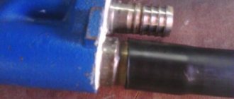
- It is necessary to take the tee and attach the fitting to it so that the fitting pipe fits inside the tee and does not protrude from it. If the pipe is too long or short, this can be corrected. In the first case, it can be ground off, and in the second, a polymer tube can be extended.
- Now you need to work with the part that will be connected to the pump. To do this, an adapter is screwed at the top of the tee.
- At the bottom of the tee, in the part where the fitting is located, a bend in the shape of an angle is screwed on. It will connect to the recirculation part of the ejector.
- An angle-type adapter is also screwed into the side of the tee. It is attached to the pipe using a collet clamp.
All connections must be sealed with special tape.