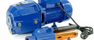
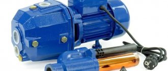
Purpose and features of water jet ejectors
The principle of operation of VES is based on Bernoulli's law. During operation of the equipment, a low-pressure area is formed in the area of narrowing the cross-section, which reduces the existing flow pressure and provokes the occurrence of suction into the flow of another medium. In fact, an ejector of this type acts as a water-jet pump, providing the vacuum necessary for pumping a liquid medium.
Purpose of the equipment:
- Use in the form of drainage and drainage devices.
- Pumping of outboard fresh or sea water.
- Distillation of domestic and waste waters, oil-containing waters.
Our catalog offers:
- Portable water jet ejectors of conventional and submersible types with open threaded ends.
- Stationary water jet models with flange connections.
In addition to water jetting equipment, you can also purchase fecal ejectors from us, which are used in sanitary ship systems, during cleaning and emergency work in sewer canals in summer cottages and during soil drainage.
Ejector. Operating principle and device. What is an ejector? Water jet ejector.
An ejector is a device in which kinetic energy is transferred from one medium moving at a higher speed to another. A pump is an actuator that converts the mechanical energy of the engine (drive) into the hydraulic energy of fluid flow. The pump, driven by the engine, communicates with the tanks by two pipelines: suction (receiving) and discharge (discharge). Based on the principle of operation, marine pumps are divided into three groups: positive displacement (displacement), vane and jet. Jet pumps have no moving parts and create a pressure difference using a working medium: liquid, steam or gas supplied to the pump under pressure. These pumps include ejectors and injectors. Jet pumps connected to the object being served by a suction pipe are called ejectors. For ejectors, the working pressure is higher than the useful one, that is. Ejectors are divided into water ones - for drying, steam - for sucking air and creating a vacuum in condensers, evaporators, etc. Jet pumps connected to the serviced object by a discharge pipe are called injectors. Injectors have the opposite pressure ratio, that is, the useful pressure is higher than the working pressure. Injectors include steam jet pumps for supplying feedwater to steam generators. Figure 1 shows a water-jet drainage ejector of the VEZH type. The ejector body 3, welded from sheet copper, has the shape of a diffuser with an angular suction pipe 7, the hole of which is closed by a cap 6 with a chain. On the left, a brass nozzle 2 is inserted into the body, having the shape of a converging nozzle with a half-nut “shtortsa” 1 for connecting a flexible hose through which working water is supplied to the ejector. To connect the outlet hose to the ejector, use a half-nut 4, located at the outlet end of the discharge pipe 5. This connection ensures the operation of portable ejectors, which are installed on the threads of deck bushings communicating through tubes with compartments or holds that require drainage.
Rice. 1 Water-jet ejector type VEZH
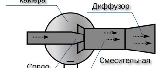
The ejector works as follows: working water is usually supplied from the fire main under pressure to the nozzle. From the narrow exit section of the nozzle, water flows at high speed into the so-called mixing chamber, and the pressure decreases. Passing through the narrow section of the diffuser (“neck”), water carries along air and creates a vacuum in the mixing chamber, which ensures the flow of liquid from the suction pipe 7. Due to friction and as a result of the exchange of impulses, the sucked water is mixed, captured and moves along with the working one. The mixture enters the expanding part of the diffuser, where the kinetic energy (speed) decreases and, due to this, the static pressure increases, facilitating the injection of the liquid mixture through pipe 5 into the discharge pipeline and overboard. The ejector feed can be adjusted by screwing in or out the nozzle. Figure 2 shows a steam jet injector used to power steam boilers. Working steam from the boiler is supplied to pipe 1 of the injector. Valve 2 is opened by turning handle 10. Steam, passing through steam nozzle 9, acquires greater speed due to a decrease in pressure. At the same time, it entrains air particles and creates a vacuum, which ensures that feed water enters the pump through pipe 3. The incoming water, mixing with the steam, condenses it. Reducing the volume increases the vacuum in the mixing chamber 4, ensuring continuous suction of feed water into the injector. The mixture of condensate and water flows through the diffuser 6 to the non-return valve 5, which covers the entrance to the boiler feed pipe. As a result of the transfer of part of the kinetic energy of the mixture into pressure, the valve opens and hot water enters the steam boiler.
Rice. 2 Steam jet injector
If the discharge pressure in front of valve 5 is less than the pressure in the boiler, the valve will not open. In this case, the water mixture in chamber 7 will press the pilot valve and will pour out through hole 8. When the pressure becomes sufficient to open valve 5, the pressure in chamber 7 will decrease and the pilot valve will close under the action of a spring, preventing water from flowing out. Steam injectors have a simple design and supply hot feed water to the steam boiler, but are ineffective and uneconomical. The absence of moving parts in the jet pump ensures pumping of liquid with various mechanical inclusions, which is used on fishing industry vessels to pump pulp, that is, a mixture of fish and water, using airlift pumps or hydraulic elevators. Unlike centrifugal fish pumps, airlifts do not damage the fish when pumping pulp. Airlifts use compressed air as a working medium, which, when mixed with water, creates a reduced density for it. The main disadvantage of jet pumps is their low efficiency, usually not exceeding that of airlifts.
What is the difference between an injector and an ejector?
- The working flow is sucked into the main pipe with a nozzle.
- The pressure in the pipe drops sharply. As soon as the speed of movement of the passive medium reaches a certain point, a vacuum is formed in the chamber. That is, the pressure becomes below atmospheric. This leads to liquid/vapor being sucked out of the nozzle.
- The ejected and ejecting media meet in a chamber where they exchange kinetic energy. When entering the diffuser, it is converted into potential compression energy. Under its action, the substance enters the outlet tube.
Operating principle of the injector
The purpose of the injector is to compress gases, vapors, liquids, and pump (spray) them into other units. The device is a standard linear accelerator that injects charged particles into the central components of the machine. Note that the water pressure in the injection unit may be higher than in the ejector unit. The physical states of the substances used are:
- equal phase (gas-gas, steam-steam, liquid-liquid);
- different phases (gas-liquid, liquid-gas);
- changing phase (vapor-liquid, liquid-vapor).
Accordingly, the injector is used as part of various equipment. It is used in the mining industry, power plants, and mechanical engineering; as an integral part of boiler equipment - in the oil and gas industry, housing and communal services, and industrial enterprises.
Injector operation diagram
As an example, let us consider the features of the operation of a steam boiler injector. It is based on its ability to create higher pressure than working steam. The kinetic energy of the latter is converted into water pressure, which enters the boiler. At its core, the injection circuit differs from the ejector circuit only in the presence of a needle valve with a handle. It is designed to regulate the flow and supply of liquid and vapor substances.
- Steam is supplied, which condenses on the cooled walls.
- Due to the pressure difference, water from the reservoir rises into the injection cavity.
- The steam expands and pulls the water flow further into the mixing chamber.
- The composition of condensed steam and water rushes forward along an expanding cone. There, its speed turns into pressure.
- This helps it overcome the resistance of the valve (outlet tube), passing through which it enters the boiler.
The design of the injector (nozzle) in automobile engines is more complex and includes moving elements.
What is the difference
Thus, an ejector and an injector are subtypes of a jet pump. They are distinguished by:
- Operating principle. The ejector pumps out gas/steam/liquid, and the injector, on the contrary, sprays.
- Design. An injection system can be more complicated than an ejector system, although they are basically identical.
- Scope of application. The ejector is used in conjunction with a vacuum pump, the injector - with boiler equipment, automobile engines, etc.
Water jet pumps
The water jet ejector is shown in Fig. 2.35. The flow rate of working water, m3/h, and weight, kg, of normalized water-jet ejectors with a pressure of 0.7 MPa, a suction height of 0.4 m and a discharge height of 0.1 MPa are as follows:
| Consumption | Weight | Consumption | Weight | ||
| VEZH 2.5 * VEZH 4 VEZH 6.3 VEZH 10 VEZH 16 VEZH 25 | 2,4 3,9 6,1 9,7 15,4 24 | 4 4,5 5,5 8 9 12 | VEZH 40 VEZH 63 VEZH 100 VEZH 160 VEZH 250 VEZH 400 | 38,5 61 91,5 154 240 385 | 18,5 33 68 87 112 171 |
The effective operation of the ejector depends on the alignment of the nozzle, mixing chamber and diffuser, as well as on the pressure difference between the working fluid at the entrance to the ejector and the liquid mixture at the exit from it.
The ability of the ejector to pump liquid along with mechanical impurities is used on fishing vessels to operate as a fish pump or hydraulic elevator, ensuring the transfer of fish from fishing gear to the vessel, from mining vessels to processing vessels, as well as for supplying fish to technological equipment. The ejector fish pump allows you to lift fish to a height of up to 2.5 m from sea level.
Rice. 2.35. Water jet ejector
The main disadvantages of water-jet fish pumping systems that limit their use are low efficiency (not higher than 10-15%) and the need to supply working fluid by centrifugal pumps under significant pressure and in large quantities.
To lift and move liquids in fish pumping installations, pneumatic lifts called airlifts, which operate on compressed air or technical gas, are widely used. They are characterized by exceptional simplicity of design and maintenance, reliability, low wear and the ability to lift liquids with various impurities and fish (pulp).
In Fig. Figure 2.36 shows an airlift diagram.
Rice. 2.36. Airlift diagram
Compressed air is supplied to the lifting pipe 6 from the compressor 3 through pipe 5. The rising air-liquid mixture at the entrance to tank 2 is directed to the baffle cone 1, where the air is separated and the liquid is discharged through pipe 4.
The airlift action is based on Fig. 2-36. Airlift diagram for the difference in levels h1 and h2 in two communicating vessels filled with liquid mixtures with different densities ρ1 and ρ2. The lifting height is determined from the equation h1/h2 = ρ2/ρ1. With an increase in the amount of supplied air, the density ρ2 of the mixture in the riser pipe decreases and the lift height h2 increases.
Test questions 1. What types of losses in pumps are taken into account using efficiency?
2. What types of pumps do you know based on their operating principle?
3. What are the main technical parameters that characterize the operation of any pump?
4. What is the working principle of a piston pump?
5. What is the reversibility of hydraulic machines and how is it achieved?
6. What are rotary pumps and what types do you know?
7. Which pumps are vane pumps, what is the principle of their operation?
8. What is cavitation and how can it be prevented?
9. What is the difference between qualitative control of the supply of centrifugal pumps and quantitative control?
10. How does a mechanical seal for rotating pump shafts differ from other types of seals?
11. What types of jet pumps do you know and what are the principles of their operation?
12. Explain the principle of operation of an airlift.
* The number in the pump index means its flow rate, m3/h.
