People have been using welding for almost a century and a half. And the famous Italian scientist Alessandro G. Volta began to study this method of connecting various objects. Based, among other things, on his scientific works, the first welding apparatus was created. The generation of an electrical discharge occurs at the moment of a short circuit (hereinafter referred to as a Short Circuit) that occurs between the surface being treated and the end of the consumable element (hereinafter referred to as the electrode). Electricity is supplied to the welding machine. Thanks to its transformation into another type of energy - thermal - a melt pool appears. This is a prerequisite for the formation of a homogeneous metal seam. Based on the results of a detailed analysis of the current-voltage characteristic (an abbreviation for the phrase Volt-ampere Characteristic), scientists managed to turn welding into practically a perfect process of connecting the elements of the structure being created. Modern devices have been developed that maintain a stable state of the welding electric arc.
Welding arc. What is this?
The electric arc produced by a welding machine is nothing more than a conductor formed by ionized particles. Its existence over a certain time interval is ensured by the support of an electric field. A similar discharge formed in a gas that is capable of ionization is characterized by:
- high temperatures;
- continuous form.
Textbooks and reference books on welding contain the following definition of this phenomenon: it is a discharge that occurs in the resulting plasma and is long-lasting. The plasma itself is a conglomerate of metal evaporation products formed under the influence of very high temperatures and which are affected by ionized protective gases present in the atmosphere.
The nature of the phenomenon
The arc formation process is as follows:
At the moment of contact, a short circuit occurs and the metal at the point of contact melts. Each stage lasts milliseconds, the discharge occurs almost instantly. The current is then maintained by the emission of electrons at the cathode. On their way to the anode, they ionize gas and metal vapor, increasing the number of free charge carriers.
Modern welding machines are equipped with a high-frequency vibration generator (oscillator). This device allows you to excite the arc in a non-contact manner.
Structure and temperature characteristics of the welding electric arc
It is quite possible to bring the temperature of a metal workpiece to the melting point in a very short period of time, but according to the laws of physics, this requires the formation of a powerful electric arc. Its main operating characteristics are:
- voltage – voltage value displayed in volts;
- amperage – electric current strength, the value of which is presented in amperes;
- level of flux density of corpuscles/charge carrier particles.
From an electrical engineering point of view, an arc column is a conductor between opposite poles (meaning positive and negative).
It is materialized through a gaseous medium. Features of the pillar are a high resistance value, the ability to produce sparks and glow. Carrying out a thorough analysis of the structure of the electric arc will reveal how temperature affects the metal. In general, its length is relatively small - it fluctuates around the 5 centimeter mark. The structure of the electric arc includes 3 areas:
- the pillar itself. This is the luminous segment visible to the human eye;
- anodic region – approximately 10 µm;
- cathode region – about 1 µm.
The temperature of the welding electric arc is determined by the flow of free electrons formed at the cathode. The heating level of the cathode itself reaches 38 percent of the temperature of the resulting plasma. Electrons - particles with a negative charge - move in a gaseous medium towards the anode, and elements carrying a positive charge move towards the cathode. In general, the following picture is observed: the pillar is neutral throughout its entire existence.
Inside the column, the temperature of the particles can reach 10,000°C. When they come into contact with metal, they heat it up to 2350°C. The point where electrons penetrate is called the anode spot by physicists. Compared to another spot, called the cathode, its temperature indicator is 6 percent higher. Plasma emits waves in the infrared, visible and UV ranges. But this radiation can harm human skin and organs of vision. Therefore, welders are required to work in special protective equipment for safety reasons.
Types of welding arc
The division of the welding electric arc into types is carried out on the basis of several characteristics. Thus, according to the criterion “Type of electric current and location of electrodes in the working area,” the following groups are formed:
- direct action. This is when the discharge is located parallel to the longitudinal axis of the electrode and perpendicular to the metal surface being processed;
- indirect action. Here the electrode is inclined to the workpiece surface at an angle of 40.0°-60.0°. The discharge passes between this consumable element and the metal;
- combined. It is a combination of the above arcs. An example is a 3-phase arc. Its 2 arcs provide electrical connection between the electrodes and the welding object. The third burns between two electrodes isolated from one another.
Depending on its composition, the plasma column can be:
- open. Formed in atmospheric gases. The feeding medium is the chemical compounds evaporating from the welding object and electrode coating;
- closed. Produced under flux. A prerequisite is the presence of a gaseous phase formed by particles that are the products of evaporation of the flux, the consumable element - the electrode, and the metal itself, which is in a liquid aggregate state;
- with the supply of a protective mixture. It can be a gas with inert properties, etc.
Another sign on the basis of which experts divide the electric arc into types is the type of electrode. The following consumables are used for welding:
- steel, the coating of which contains inclusions that ensure gas ionization;
- made from coal or graphite;
- refractory, made of tungsten metal (element W).
According to the “exposure time” criterion, the welding electric arc can be pulsed or constant.
What current-voltage characteristics can welding power sources have?
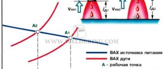
Comment: Welding arc power sources also have their own current-voltage characteristics , which can be falling, hard and rising (Fig. 1).
Rice. 1. Volt-ampere characteristics of welding arc power sources: a - falling; b - hard; in - increasing
For stable arc burning it is necessary that there be equality between the voltages and currents of the arc (Ud, Id) and the power source (Up, Ip).
Power sources with a decreasing characteristic are used for manual arc welding, with a rigid characteristic for semi-automatic welding, and with an increasing characteristic for automatic submerged arc welding and surfacing.
Stable burning of the welding arc is possible only if the power source of the welding arc maintains constant the required voltage when current flows through the welding circuit.
The operation of the welding circuit and arc must be considered when superimposing the static current-voltage characteristic (CVC) of the welding arc on the static current-voltage characteristic of the power source (also called the external characteristic of the power source) - Fig. 2. In this case, the voltage and current of the power source and arc coincide at two points 1 and 2. Only point 1 corresponds to stable combustion of the welding arc.
When the arc current decreases, the source voltage will become greater than the arc voltage, since the operating point on the power source characteristic will shift to the left, the excess voltage of the power source will lead to an increase in the arc current, i.e., to the process returning to point 1.
Source
Combustion conditions
The welding process is based on the transformation of electricity into thermal energy. The retention time of the column formed during its course is not limited in any way if the ionization of the gas occurs very quickly. When welding, the workpieces are heated, the air in contact with them becomes hot and is enriched with evaporated substances. An alternative method is to specially supply a gas to the working area, from the molecules or atoms of which ions are formed under external influence. The particles of soft alkali metals (included in the first group of the periodic table), as well as alkaline earth metals (these are already representatives of the second group of the periodic table), are most well ionized. To transfer them to an active state, it is enough to start passing an electric current.
Another prerequisite for reliable maintenance of the welding column is a high, stable temperature of the cathode over time. Its value is a characteristic derived from the area of the cathode itself, as well as its chemical composition. You cannot do without a source of electricity here. When welding work is performed, the temperature of the cathode zone reaches 7000°C.
Selecting a Power Source for Arc Welding
Of course, in addition to power characteristics, welding equipment is selected based on mobility, size, and weight. Speaking about the advantages and disadvantages of power sources, it is worth starting with the very first type of welders.
Transformer
Equipment with a secondary winding converts the voltage; due to inductive fields, the voltage from 80 volts can be lowered to 20. This is the simplest and most cumbersome type of welding machine. But it is very reliable, depends little on environmental conditions, and is not afraid of humidity or dust. You can build a transformer yourself; the required voltage is obtained by a certain number of turns of the secondary winding. The efficiency of the equipment is quite high, the cost is low. When the amount of work is small, welders with experience prefer to purchase transformers for the garage or home.
Rectifier
Already from the name it is clear that we are talking about a direct current source. Semiconductors are used for conversion; they transmit electricity only in the upper range of the sine wave. Due to the use of semiconductors and the presence of an electrical circuit, the capabilities of rectifiers are wider than those of transformers. When changing the polarity, you can adjust the temperature at the contacts: with direct polarity, the electrode heats up more, with reverse polarity, the metal heats up more. The efficiency of rectifiers is higher than that of transformers, and there are low no-load losses.
The big disadvantage is that welding machines get very hot, they periodically need a break to return to normal or an additional cooling system.
Generator
Electricity is generated by rotating the shaft in a constant magnetic field. The devices operate on gasoline and diesel fuel; there are stationary installations on coal and briquetted fuel. Main advantages:
Cons: large dimensions, low efficiency, plus exhaust gases, noise, vibration.
How an electric arc is formed
A welding arc is nothing other than an electrical discharge. It appears when the circuit is closed. At the moment of contact of the electrode with the structural element being welded, thermal energy begins to be produced in excess. The metal melts at the point of contact. Due to the phenomenon of attraction of the melt to the tip of the consumable element, a thin neck is formed. Under the influence of a powerful electric field, it is practically instantly sprayed. This causes the ionization of gas molecules. As a result of this process, a protective cloud is formed, ensuring the free movement of electrons.
The direction of the flow is determined by the type of current. An electric arc can be ignited using an electric current of both constant and variable magnitude, as well as any polarity - both direct and reverse. The frequency of arc ignition and extinction is a characteristic derived from the set of current parameters selected by the worker.
How to adjust arc length
Not only electrical quantities, but also the quality of welding depend on this parameter. They strive to make the arc as short as possible, within 3-4 mm.
With a longer length, the following negative phenomena are observed:
- Drops of molten metal from the electrode on the way to the weld pool manage to absorb a lot of oxygen and nitrogen from the air. As a result, the seam loses strength, ductility and toughness.
- The discharge moves along the surface of the workpiece (wandering), as a result of which the heat is distributed over a relatively large area. The penetration depth decreases; drops of melt from the consumable, falling on unheated metal, do not merge with it, but bounce off.
We recommend reading: What to do if your eyes hurt from welding
A short arc produces a dry crackling sound, reminiscent of oil sizzling in a hot frying pan.
With a long welding arc, negative phenomena are observed.
The seam she made looks neat and has the following characteristics:
- Correct form.
- Smooth convex surface.
The seam, made with a long arc, has uneven outlines, and drops of molten metal stick along it.
The consumable electrode decreases during the welding process. Therefore, it is gradually brought closer to the workpiece so that the discharge length remains constant.
What affects the power of the electric arc
The power indicators of the welding electric arc depend on the following main factors:
- supply voltage. An increase in supply voltage leads to an increase in arc power. However, the range of changes in the values of the last parameter is not wide. There are also restrictions regarding the size of the electrodes;
- current strength. The dependence is directly proportional. As this parameter increases, the stability of the electric arc increases;
- The dependence of the power and the numerical value of the voltage of the resulting plasma is also directly proportional.
The arc length is the distance from the consumable element to the surface to be welded during the work. This indicator affects the amount of heat generated.
The rate of metal melting is determined by the power of the electric arc. This parameter is very important. After all, it depends on how long it takes to connect the metal parts. The temperature in the melting region is changed by the current strength. If it is large enough, the electric arc will not go out even of considerable length. It is very rare to adjust the amperage during welding.
Classification
It is generally accepted to gradate power supplies according to several criteria, determined by the electromechanical properties of electric current sources. Beginner welders just need to know the basic classification criteria:
To power the welding arc, there are two ways to obtain operating current:
Grouping by type of generated current:
Method of converting electricity: by changing voltage and amperage, by rectification - alternating current is converted into direct current.
Mobility of sources, arc power can be stationary (connection to main power grids) and autonomous (use of portable generators or batteries).
A method for adjusting arc operating parameters (voltage, amperage). In transformers, the number of turns involved changes: the position of the shunt, the mobility of the coil, and the sectioning of the secondary winding.
The gradation of power sources according to the external characteristics of the welding arc current is an assessment of the dependence of the average voltage at the contacts (electrode holder and terminal fixed on the metal) on amperage. The parameters of the current-voltage characteristics of equipment are of two types:
The current-voltage characteristic of the source is determined experimentally. When the power is connected, the voltage at the terminals is measured.
I-V characteristics of the welding arc
The abbreviation VAC stands for: current-voltage characteristic.
It displays the relationship between power parameters. From the current-voltage characteristic you can find out the time of stable burning of the electric arc, its power, as well as the damping conditions. The dynamics with which the current-voltage indicators change reflects the variation in the length of the electric arc when it is unstable. And vice versa, the static current-voltage characteristic shows how the voltage of the electric arc depends on the current strength during the period of constancy of its length. The above graph, divided into 3 segments, expresses its properties.
Falling current-voltage characteristic
An increase in current is accompanied by a sharp drop in voltage (section “1” on the graph). This is due to the formation of the column. As the plasma flow increases, its electrical conductivity changes. And in the direction of increase.
Hard current-voltage characteristic
The key feature of this section (position “2” on the graph) is a reduced voltage, combined with a current density that is constant over time. The current strength varies between 100V-1000V. The diameter of the electric arc column increases, and its resistance, accordingly, decreases. The area of the spots, both anodic ("+" sign) and cathodic ("-" sign), increases proportionally.
Increasing current-voltage characteristic
On the graph this is section “3”. It is distinguished by the stability of the cathode spot. Its size is a derivative of the diameter of the consumable element. The resistance of the welding column increases. An increase in voltage across the arc is also observed.
The following points should be specially noted:
- when consumable or non-consumable consumables are used for manual electric welding, the current-voltage characteristics do not transfer to the third section of the graph. For this case, only the first two are relevant;
- indicators of plot sections numbered 2 and 3 describe mechanized welding, which involves the use of fluxes;
- welding parameters in a protective environment using a consumable electrode are displayed in the third segment of the graph.
Now a few words about the operation of welding equipment on alternating current. The electric arc is excited at the peak of ignition in all half-cycles. Its attenuation is observed at the moment the sinusoid passes the zero mark. Active spots stop heating. The endothermic process of the formation of ions from elementary neutral gas particles is maintained in a stable state by evaporation of alkaline group metals present in the coating of the electrodes. The process of igniting an electric arc in a protective environment using an electric current with a time-varying value is more difficult compared to welding using constant current.
When choosing a device for carrying out work of a certain type, it is necessary to take into account the direct dependence of the current-voltage characteristic on the current-voltage parameters of the external order. For example, manual electric arc welding will be performed successfully with a power supply characterized by a falling current-voltage characteristic, that is, with an increased voltage value at idle. In this case, the worker will have the opportunity to change the length of the electric arc using an amperage regulator.
The magnitude of the current recorded during a short circuit during the melting of the consumable element exceeds the value of this column indicator by 20 to 50 percent. Welding using consumable electrodes is the best option when using a trip arc. And here you need to know one thing. It is formulated as follows: to ignite an electric arc with a tungsten or carbon consumable element, an auxiliary/additional discharge will be very useful.
The significant current that occurs during a short circuit can lead to burning of the workpiece. A short circuit occurs when a drop of melt from the consumable element falls. After this, the parameters suddenly return to their original values. As a result, an increase in amperage is observed, and the current instantly reaches the level recorded during a short circuit. The bridge formed between the electrode and the metal workpiece burns out very quickly. This leads to another excitation of the electric arc. All of the above changes are carried out in the electric arc column almost instantly. The equipment must respond within this short time interval for performance to stabilize.
To main§ 8. WELDING PROPERTIES OF ARC
A welding arc is a powerful, stable electric discharge in a gas environment formed between the electrodes, or between the electrodes and the product. The welding arc is characterized by the release of a large amount of thermal energy and a strong light effect. It is a concentrated heat source and is used to melt base and filler materials. Depending on the environment in which the arc discharge occurs, there are: an open arc burning in the air, where the composition of the gas environment of the arc zone is air mixed with vapors of the metal being welded, the material of the electrodes and electrode coatings; a closed arc burning under a submerged arc, where the composition of the gaseous medium of the arc zone is a pair of base metal, wire and protective flux; an arc burning in an environment of protective gases (the gaseous environment of the arc zone includes an atmosphere of protective gas, pairs of wire and base metal). The welding arc is classified by the type of current used (direct, alternating, three-phase) and by the duration of combustion (stationary, pulsed). When using direct current, an arc of direct and reverse polarity is distinguished. With direct polarity, the negative pole of the power circuit - the cathode - is located on the electrode, and the positive pole - the anode - is on the base metal. With reverse polarity, the plus is on the electrode and the minus is on the product. Depending on the type of electrode used, the arc can be excited between consumable (metal) and non-consumable (carbon, tungsten, etc.) electrodes. According to the principle of operation, arcs can be of direct, indirect and combined action (Fig. 14).
Straight arc
called an arc discharge occurring between the electrode and the product.
An indirect arc
is an arc discharge between two electrodes (atomic-hydrogen welding).
A combined arc
is a combination of a direct and indirect arc. An example of a combined arc is a three-phase arc, in which two arcs electrically connect the electrodes to the workpiece, and the third burns between two electrodes isolated from each other. The arc is excited in two ways: by touching or by striking, the essence of which is shown in Fig. 15.
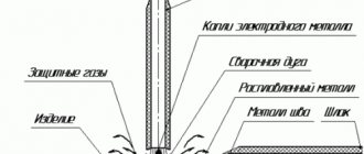
In a welding arc, the arc gap is divided into three main regions: anodic, cathodic and arc column. During the arcing process, there are active spots on the electrode and base metal, which are more heated areas of the electrode and base metal through which the entire arc current passes. The active spot located on the cathode is called cathode
, and the spot located on the anode is
anodic
.
The total length of the welding arc (Fig. 16) is equal to the sum of the lengths of all three areas:
L
d =
L
k +
L
c +
L
a,
where L
d - total length of the welding arc,
cm
;
L
k is the length of the cathode region, equal to approximately 10-5
cm
;
L
с - length of the arc column,
cm
;
Ld
is the length of the anode region, equal to approximately 10-3 ÷ 10-4
cm
. The total voltage of the welding arc is composed of the sum of the voltage drops in individual areas of the arc:
U
d =
U
k +
U
c +
U
a,
where U
d - total voltage drop across the arc,
in
;
Uk
is the voltage drop in the cathode region,
in
;
U
c is the voltage drop in the arc column,
in
;
U
a is the voltage drop in the anode region,
in
. The temperature in the welding arc column ranges from 5000 to 12,000° K and depends on the composition of the gaseous medium of the arc, material, electrode diameter and current density. The temperature can be approximately determined using the formula proposed by Academician of the Academy of Sciences of the Ukrainian SSR K. K. Khrenov:
T
st = 810
Ueff
,
where T
sm—arc column temperature, °K;
Ueff
—effective ionization potential.
Static current-voltage characteristics of the welding arc.
The dependence of the voltage in the welding arc on its length and the magnitude of the welding current, called the current-voltage characteristic of the welding arc, can be described by the equation
U
d +
a
+
bL
d,
where a
- the sum of the voltage drops at the cathode and anode (
a
=
U
k +
U
a):
b
- specific voltage drop in the gas column per 1
mm
of arc length (the value of
b
depends on the gas composition of the arc column);
L
d - arc length,
mm
.
At low and ultra-high current values, U
d depends on the value of the welding current.
The static current-voltage characteristic of the welding arc is shown in Fig. 17. In region I,
an increase in current to 80
A
leads to a sharp drop in arc voltage, which is due to the fact that with low-power arcs, an increase in current causes an increase in the cross-sectional area of the arc column, as well as its electrical conductivity.
The shape of the static characteristics of the welding arc in this section is falling. A welding arc with a falling current-voltage characteristic has low stability. In region II
(80 - 800
A
), the arc voltage remains almost unchanged, which is explained by an increase in the cross-section of the arc column and active spots in proportion to the change in the welding current, therefore the current density and voltage drop in all areas of the arc discharge remain constant.
In this case, the static characteristic of the welding arc is rigid. This arc is widely used in welding technology. When the welding current increases to more than 800 A
(region
III
), the arc voltage increases again. This is explained by an increase in current density without growth of the cathode spot, since the electrode surface is no longer sufficient to accommodate a cathode spot with a normal current density. The arc with increasing characteristics is widely used in submerged arc and shielding gas welding.
Processes occurring at the moment of excitation of the welding arc.
In the event of a short circuit, the end of the electrode comes into contact with the product. Since the end of the electrode has an uneven surface, contact does not occur along the entire plane of the end of the electrode (Fig. 18). At the points of contact, the current density reaches very high values and, under the influence of the released heat at these points, the metal instantly melts. At the moment the electrode is removed from the product, the zone of molten metal - the liquid bridge - stretches, the cross-section decreases, and the temperature of the metal increases. When the electrode is removed from the product, the liquid bridge of the metal breaks, and rapid evaporation occurs (an “explosion” of the metal). At this moment, the discharge gap is filled with heated ionized particles of metal vapor, electrode coating and air - a welding arc occurs. The arcing process lasts only a fraction of a second. Ionization of gases in the arc gap at the initial moment occurs as a result of thermionic emission from the surface of the cathode, due to structural damage as a result of sudden overheating and melting of the metal and electrode coating.
An increase in the electron flux density also occurs due to oxides and the formed surface layers of molten fluxes or electrode coatings, which reduce the electron work function. At the moment the bridge of the liquid metal breaks, the potential drops sharply, which contributes to the formation of field emission. A drop in potential makes it possible to increase the emission current density, accumulate kinetic energy for electrons for inelastic collisions with metal atoms and transfer them to an ionized state, thereby increasing the number of electrons and, consequently, the conductivity of the arc gap. As a result, the current increases and the voltage drops. This happens up to a certain limit, and then a steady state of the arc discharge begins - arc burning. Cathode region.
Processes occurring in the region of the cathode voltage drop play an important role in welding processes.
The region of the cathode voltage drop is a source of primary electrons, which maintain the arc gap gases in an excited ionized state and carry the bulk of the charge due to their high mobility. The removal of electrons from the cathode surface is caused primarily by thermionic and field emission. The energy spent on tearing electrons from the cathode surface and fusing the metal is, to some extent, replaced by energy from the arc column due to the flow of positively charged ions that release their ionization energy on the cathode surface. The processes occurring in the region of the cathode voltage drop can be represented according to the following diagram. 1. Electrons, emitted from the surface of the cathode, receive accelerations necessary for the ionization of gas molecules and atoms. In some cases, the cathode voltage drop is equal to the ionization potential of the gas. The magnitude of the cathode voltage drop depends on the ionization potential of the gas and ranges from 10 to
16
V. 2. Due to the small thickness of the cathode zone (about 10-5 cm
), electrons and ions move in it without collisions and it is approximately equal to the free path of an electron.
The values of the thickness of the cathode zone, found experimentally, are less than 10-4 cm
.
3. With increasing current density, the temperature of the cathode region increases. Arc pillar.
In the arc column there are three types of charged particles - electrons, positive ions and negative ions, which move to the opposite pole.
The arc column can be considered neutral, since the sum of the charges of negative particles is equal to the sum of the charges of positive particles. The arc column is characterized by the formation of charged particles and the reunification of charged particles into neutral atoms (recombination). The flow of electrons through the gas layer of the discharge gap causes mainly elastic collisions with gas molecules and atoms, as a result of which a very high temperature is created. Ionization as a result of inelastic collisions is also possible. The temperature of the arc column depends on the composition of the gases, the magnitude of the welding current (as the current increases, the temperature increases), the type of electrode coatings and polarity. With reverse polarity, the temperature of the arc column is higher. Anode region.
The anodic region has a larger extent and a smaller voltage gradient than the cathodic region.
The voltage drop in the anode region is created as a result of the extraction of electrons from the arc discharge column and acceleration as they enter the anode. In the anode region there is mainly only an electron current, due to the small number of negatively charged ions, which have lower velocities than the electron. An electron that hits the anode surface gives the metal not only a supply of kinetic energy, but also work function energy, so the anode receives energy from the arc column not only in the form of a flow of electrons, but also in the form of thermal radiation. As a result, the anode temperature is always higher and more heat is generated on it. Features of a welding arc fed by alternating current.
When welding with an alternating current arc (industrial frequency 50 cycles per second), the cathode and anode spots change places 100 times per second.
When the polarity changes, the so-called “valve effect” is formed, which consists in partial rectification of the current. Current rectification occurs as a result of continuously changing electron emission, since when the direction of the current changes, the conditions for the release of emission currents from the electrode and from the product will not be the same. With the same materials, the current is almost not rectified; the rectification of the current in the welding arc is called the direct current component
, which during argon-arc welding of aluminum has a negative effect on the process. The combustion stability of a welding arc fed by alternating current is lower than that of an arc fed by direct current. This is explained by the fact that as the current passes through zero and changes polarity at the beginning and end of each half-cycle, the arc dies out. At the moment of arc extinction, the temperature of the arc gap decreases, causing deionization of the gases of the arc column. At the same time, the temperature of active spots also drops. The temperature especially drops at the active spot, which is located on the surface of the weld pool, due to heat dissipation into the product. Due to the thermal inertia of the process, the temperature drop is slightly behind the phase of the current passing through zero. Ignition of the arc due to reduced ionization of the arc gap at the beginning of each half-cycle is possible only with an increased voltage between the electrode and the product, called the ignition peak. If the cathode spot is located on the base metal, then in this case the magnitude of the ignition peak is slightly higher. The magnitude of the ignition peak is influenced by the effective ionization potential: the higher the effective ionization potential, the higher the ignition peak should be. If there are easily ionized elements in the welding arc, the ignition peak decreases and, conversely, it increases if there are fluorine ions in the arc atmosphere, which, when combined with positive ions, easily form neutral molecules. The main advantages of an alternating current arc include: relative simplicity and lower cost of equipment, the absence of magnetic blast and the presence of cathode sputtering of an oxide film during argon-arc welding of aluminum. Cathode sputtering is the process of bombarding the weld pool with positive ions at the moment when the product is the cathode, due to which the oxide film is destroyed.
The influence of the magnetic field and ferromagnetic masses on the welding arc
In a welding arc, the arc column can be considered as a flexible conductor through which an electric current passes and which can change its shape under the influence of an electromagnetic field. If conditions are created for the interaction of the electromagnetic field arising around the welding arc with extraneous magnetic fields, with the own field of the welding circuit, as well as with ferromagnetic materials, then in this case a deviation of the arc discharge from the original own axis is observed. In this case, the welding process itself is sometimes disrupted. This phenomenon is called magnetic blast
. Let's look at a few examples showing the effect of an external magnetic field on a welding arc. 1. If a symmetrical magnetic field is created around the arc, then the arc does not deviate, since the created field has a symmetrical effect on the arc column (Fig. 19, a).
2. The welding arc column is affected by an asymmetrical magnetic field, which is created by the current flowing in the product; the arc column will deviate in the direction opposite to the current conductor (Fig. 19.6). The angle of inclination of the electrode, which also causes deflection of the arc, is also significant (Fig. 20).
A strong factor acting on arc deflection is ferromagnetic masses: massive welded products (ferromagnetic masses) have greater magnetic permeability than air, and magnetic field lines always tend to pass through the medium that has less resistance, therefore an arc discharge located closer to ferromagnetic mass, always deviates in its direction (Fig. 21).
The influence of magnetic fields and ferromagnetic masses can be eliminated by changing the location of the current supply, the angle of inclination of the electrode, by temporarily placing ferromagnetic material to create a symmetrical field and replacing direct current with alternating current.
Transfer of molten metal through the arc space
When transferring molten metal, the forces of gravity, surface tension, electromagnetic field and internal gas pressure act. The force of gravity manifests itself in the tendency of the drop to move downward under its own weight. When welding in the lower position, gravity plays a positive role in transferring the drop into the weld pool; when welding in vertical and especially in overhead positions, it complicates the process of transferring electrode metal. The force of surface tension is manifested in the desire of a liquid to reduce its surface under the influence of molecular forces, seeking to give it a shape that would have a minimum amount of energy. This form is a sphere. Therefore, the force of surface tension gives a drop of molten metal the shape of a ball and retains this shape until it comes into contact with the surface of the molten bath or the drop is torn off from the end of the electrode without contact, after which the surface tension of the bath metal “pulls” the drop into the bath. The force of surface tension helps to retain the liquid metal of the bath during welding in the ceiling position and creates favorable conditions for the formation of a seam. The strength of the electromagnetic field lies in the fact that the electric current passing through the electrode forms a magnetic force field around it, which has a compressive effect on the surface of the electrode, tending to reduce the cross-section of the electrode. The magnetic force field does not affect solid metal. Magnetic forces acting normal to the surface of a spherical molten drop have a significant effect on it. With an increase in the amount of molten metal at the end of the electrode, under the action of surface tension forces, as well as compressive magnetic forces, an isthmus is formed in the area between the molten and solid electrode metal (Fig. 22).
As the cross section of the isthmus decreases, the current density sharply increases and the compressive effect of magnetic forces, tending to tear the drop from the electrode, intensifies. Magnetic forces have a minimal compressive effect on the spherical surface of the droplet facing the molten pool. This is explained by the fact that the current density in this part of the arc and on the product is small, so the compressive effect of the magnetic force field is also small. As a result, the metal is always transferred in the direction from the small-section electrode (rod) to the large-section electrode (product). It should be noted that in the resulting isthmus, due to an increase in resistance during the passage of current, a large amount of heat is released, leading to strong heating and boiling of the isthmus. The metal vapors formed during this overheating at the moment of separation of the drop have a reactive effect on it - they accelerate its transition to the bath. Electromagnetic forces contribute to the transfer of metal in all spatial welding positions. The force of internal gas pressure arises as a result of chemical reactions, which proceed more actively the more the molten metal at the end of the electrode is overheated. The starting products for the formation of reactions are gases, and the volume of gases formed is tens of times greater than the volume of the compounds involved in the reaction. The separation of large and small drops from the end of the electrode occurs as a result of violent boiling and the removal of formed gases from the molten metal. The formation of splashes on the base metal is also explained by the explosive fragmentation of the drop when the drop passes through the arc gap, since at this moment the release of gases from it increases, and some part of the drop flies out of the weld pool. The force of internal gas pressure mainly moves the droplet from the electrode to the workpiece.
Main indicators of the welding arc
Melting coefficient.
When welding metal, a seam is formed due to the melting of the filler metal and penetration of the base metal. The melting of the filler metal is characterized by the melting coefficient
where αр is the melting coefficient; G
the electrode metal
melted during time
t g ; t
is the arc burning time, h;
I
is the welding current,
and
.
The melting coefficient depends on the composition of the wire and electrode coating, the weight of the coating, as well as the type and polarity of the current. Loss ratio.
The coefficient characterizes the loss of electrode metal due to splashing, evaporation and oxidation.
where ψ is the loss coefficient; G
n—weight of deposited metal,
G
;
G
r - weight of molten metal
,
G. The loss coefficient depends not only on the composition of the wire and its coating, but also on the welding mode and the type of welded joint. The loss factor increases with increasing current density and arc length. It is somewhat smaller when welding tees, with cutting edges, than when surfacing. Deposition factor.
To evaluate the surfacing process, the concept of surfacing coefficient is introduced:
where αн is the deposition coefficient; G
n—amount of metal deposited during time
t
,
g
(including losses).
The deposition rate depends on the type and polarity of the current, the type of coating and composition of the wire, as well as on the spatial position in which welding is performed. Dependence of the welding current on the electrode diameter.
In manual arc welding, the welding current and the diameter of the electrode are related by the following relationship:
I
=
K d
,
where I
is the magnitude of the welding current,
and
;
K
- coefficient depending on the brand of electrode (
K
= 40 ÷ 60; 40 - for alloy electrodes, 60 - for carbon electrodes)
d
- electrode diameter,
mm
.
The given formula is applicable for electrodes with a diameter of 8 - 6 mm
. The relationship between the diameter and the welding current is also expressed by the following experimental formula:
I
= (
m
+
n d
)
d
,
where m
= 20;
n
= 6 (for manual welding with steel electrodes).
Productivity of the arc welding process.
Welding performance is determined by the amount of deposited metal
G
= αн ·
I · t
,
where G
— weight of deposited metal
,
G. The higher the current, the higher the performance. However, with a significant increase in the welding current for the applied electrode diameter, the latter can quickly be heated by Lenz-Joule heat, which will sharply reduce the quality of the weld, since the weld metal and the fusion zone of the base metal will be overheated. It should be noted that overheating the electrode increases metal spattering. Running energy.
The ratio of the effective thermal power of the arc (source)
q
n to the speed of movement of the arc
v
is called
heat input
.
where v
— arc movement speed (welding speed),
cm/sec
. Heat input is the amount of heat in calories introduced per unit length of a single pass weld or bead. The total thermal power of the welding arc is approximately equal to the thermal equivalent of its electrical power
Q
= 0.24
U
d
I cal/sec
,
where Ud is the voltage drop across the arc, in
;
I
is the magnitude of the welding current,
and
;
Q
is the thermal equivalent of the electric power of the welding arc,
cal/sec
.
The amount of heat introduced by the welding arc into the product during its heating per unit time is called effective thermal power of the welding arc
, which is the sum of the thermal energy released in the arc spot on the product, introduced into the product during heat exchange with the arc column and the spot on the product, and entering with drops of molten flux, electrode metal and coating:
q
u = 0.24
U
d
I h
and
cal/sec
,
where q
and is the effective thermal power of the welding arc
cal/sec
;
h
and is the effective efficiency. process of heating metal with a welding arc, From
Efficient efficiency process of heating metal with a welding arc
is the ratio of the amount of heat introduced into the metal to the thermal equivalent of the electric power of the arc. This coefficient characterizes the efficiency of the processes of heat release and heat exchange in the arc gap in relation to the heating of the metal of the product and depends mainly on the welding method. In Fig. Figure 23 shows the thermal balance of the heat generated by the arc, from which it can be seen that the heat of the arc is used more fully in automatic submerged arc welding.
As the arc length increases, the effective efficiency falls and increases as the arc deepens into the bath. When welding with metal electrodes, this coefficient depends little on the type, polarity and magnitude of the welding current.
Self-test questions
1. What is an electric arc?
2. Name the main sections of the electric arc. 3. As a result of what phenomena does ionization of the air gap between the electrode and the product occur? 4. How to determine the melting, deposition and loss coefficients? 5. What is heat input called? Previous page
| table of contents | Next page |
Features of the electric arc
The wide range of parameters changes determines the compatibility of the electric arc with conventional consumable consumables, as well as with refractory ones. As a result of its influence, the workpiece heats up very quickly, and then a melt pool is formed. The level of losses occurring during the conversion of electrical energy into thermal energy is minimal. Although the nature of the electric arc can be compared with discharges of other types, it has its own characteristics:
- self-regulating current-voltage characteristics, as well as power;
- spatial stability;
- clear contours;
- uneven distribution between both poles of the electric field;
- a slight decrease in voltage at the anode ("+" sign) and cathode ("-" sign). This phenomenon has little to do with the initially set voltage;
- strong current produces high temperature.
The arc can be ignited in two ways: by briefly touching or by striking.