Determining the required volume of paints and varnishes and assessing the financial costs of metal processing is impossible without calculating the area to paint metal structures.
Most organizations that provide painting of metal structures include the cost of this service in calculating the total cost of metal structures per 1 m². This method of calculation is quite acceptable when processing parts with more or less smooth surfaces, the area of which can be calculated without much difficulty.
However, if metal structures have a complex shape, this method is not used. This can be explained very simply: calculating the channel area is a complex process, and for openwork products it is not at all a feasible task. In these cases, it is customary to calculate the cost of painting metal structures per 1 ton, which significantly simplifies the process and avoids errors.
Today, a large number of coefficients are used to calculate the area to paint metal structures.
Below are tables with coefficients for correct calculation.
| Profile name, number and section thickness | Surface area, sq.m/1 t. profile | Profile name, number and section thickness | Surface area, sq.m/1 t. profile | Profile name, number and section thickness | Surface area, sq.m/1 t. profile | ||
Sheet steel and open bent profiles
(the surface is shown as a total on both sides)
sheet thicknesssheet thicknesssheet thickness2,0127,67,036,622,011,82,2115,98,032,125,010,42,5102,39,028,528,09,42,891,210,025,730,08,738511,023,432,08,23, 279,912,021,536,07,33,573,014,018,440,06,64,063,916,016,245,05,95,051,118,014,450,05,46,042,720,013,055 .04.9Reinforcement cross-sectional area
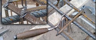
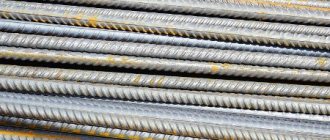
Reinforcement is a metal product in the form of a rod used in construction. A reinforcement section is an image of a figure formed by cutting the reinforcement by a plane in the transverse direction.
Formula for calculating the cross-sectional area of reinforcement: S = π * d 2 / 4
, where d is the diameter of the reinforcement.
Reinforcement section
You need to know about the cross section and calculate (you need to know the S-circle). It is calculated by the formula: The area of a circle is found by the formula: PxR2, where R2 is the radius of the circle; P-3.14. For rods with a diameter of 14 mm, the calculation will be as follows:
R=14:2:1000=0.007 m.
S=3.14×0.007×0.007=0.0001;
Next, we determine the V rod. You need to know the length of the product in meters (for example, 14m). V=14×0.0001=0.014;
- Then we multiply the obtained result by the volumetric weight of the product 0.014 * 7856 = 109 kg.
- The weight of the rod is very important for construction, therefore, correct calculations will help make a reliable foundation that can last a long time and can withstand heavy loads.
- Table of fittings assortment GOST 5781-82:
Reinforcement is produced by hot rolling. After the material reaches the plant, it is unloaded, carefully sorted and placed in a liquid state for melting. Next it is poured into a mold.
After the steel ingots harden, they are heated. After this procedure, the product is placed in a refrigeration chamber to cool, quality control, cutting and preparation for transportation are carried out.
The reinforcement is produced in the form of rods or coils.
How to determine the area of reinforcement: calculation table
The cross-sectional area of the reinforcement is one of the most important parameters determining strength. The higher the expected load, the larger the area should be. To find out this data, you need to contact your sales consultant or read the product data sheet. If the product is purchased second hand, you will have to make the calculation yourself.
To do this, you must follow these instructions:
- Measure the diameter. A caliper will help. It is necessary to take into account that the result may not be a round unit, so it is rounded based on mathematical rules.
- Determine the cross-sectional area of the reinforcement based on its diameter using a special table. With its help, you can calculate how much 1 meter of reinforcement weighs and how many meters are in a ton of reinforcement.
Reinforcement assortment table, weight of 1 meter and diameter.
| Cross section, area, cm² | Diameter of fittings, mm | Weight of linear meter of reinforcement, g | How much reinforcement in a ton, m |
| 0,283 | 6 | 222 | 4505 |
| 0,503 | 8 | 395 | 2532 |
| 0,785 | 10 | 617 | 1620 |
| 1,131 | 12 | 888 | 1126 |
| 1,54 | 14 | 1210 | 826 |
| 2,01 | 16 | 1580 | 633 |
| 2,64 | 18 | 2000 | 500 |
| 3,14 | 20 | 2470 | 405 |
| 3,8 | 22 | 2980 | 336 |
| 4,91 | 25 | 3850 | 260 |
| 6,16 | 28 | 4830 | 207 |
| 8,04 | 32 | 6310 | 158 |
| 10,18 | 36 | 7990 | 125 |
| 12,58 | 40 | 9870 | 101 |
| 15,48 | 45 | 12480 | 80 |
Thanks to the table, you can easily determine other data, for example, how many meters are in a ton of 12 mm reinforcement. We look for indicator 12 in the diameter column and find the corresponding value in the length column. This parameter is 1126 m.
Closed bent square, rectangular and pipe profiles
(the surface is shown on the outside of the rental)
wall thicknesswall thicknesswall thickness2,065,28,016,618,07,52,552,19,014,520,06,73,043,510,013,122,06,13,537,311,011,825,05,54,032,912,010,828,05,05, 026,514,09,330,04,76,022,016,08,132,04,47,019,017,07,640,03,5General information about cable and wire
When working with conductors, it is necessary to understand their designation.
There are wires and cables that differ from each other in their internal structure and technical characteristics. However, many people often confuse these concepts. A wire is a conductor that has in its design one wire or a group of wires woven together and a thin common insulating layer. A cable is a core or a group of cores that has both its own insulation and a common insulating layer (sheath). Each type of conductor will have its own methods for determining cross sections, which are almost similar.
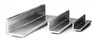
Equal flange angle steel
half-kit thickness half-kit thickness shelf thickness 3,086,59,029,520,013,34,065,010,026,322,012,05,052,012,022,025,010,66,044,014,019,028,09,67,037,016,016,630,09 .08.033.018.014.9Tables for selecting a suitable conductor
A convenient and practical option for selecting the desired wire (cable) is to use special tables that indicate the diameters and cross-sections relative to the power and/or currents carried.
Having such a table at hand is an easy and simple way to quickly determine the conductor for the required electrical installation. Determining the required values using a classic table is one of the most convenient ways to select the required conductor during installation work. Considering that traditional conductors for electrical installations are products with copper or aluminum conductors, there are tables for both types of metals.
Also, tabular data often presents values for voltages of 220 volts and 380 volts. Plus, the installation conditions are taken into account - closed or open wiring. In fact, it turns out that one sheet of paper or a picture loaded into a smartphone contains voluminous technical information that allows you to do without the above-mentioned mathematical (linear) calculations.
Moreover, many manufacturers of cable products, in order to make it easier for the buyer to choose the right conductor, for example, for installing sockets, offer a table in which all the necessary values are entered. All that remains is to determine what load is planned for a specific electrical point and how the installation will be performed, and based on this information, select the correct wire with copper or aluminum conductors.
Hot rolled channels
(the surface is shown as a total on all sides)
profile number profile number profile number 547,11640,522А34,96,546,416А38,72435,0845,41839,324А33,31044,718А37,72733,21243,12038,33031,41441,620А36,43329,614А3 9.72236.63627.74026.1Calculation goals
Cross-section of wires for lighting
It is necessary to calculate the parameters of the cross-sectional area of the conductor for several purposes:
- obtaining the required amount of electricity to power household appliances;
- eliminating overpayments for unused energy;
- wiring safety and fire prevention;
- the ability to connect high-power equipment to the network;
- prevention of melting of the insulating layer and short circuits;
- proper organization of the lighting system.
The optimal wire cross-section for lighting is 1.5 mm2 for the line, 4-6 mm2 for the input.
I-beams
(the surface is shown as a total on all sides)
profile number profile number profile number 1044,42038,13626,71243,12236,74024,91441,82434,44523,21640,52733,05021,41839,13031,25519,76018,1Which cable to choose for apartment wiring
Despite the cheapness of aluminum conductors, it is better to avoid using them. The reason is the low reliability of the contacts through which currents will pass. The second reason is the mismatch of the wire cross-section with the power of modern household appliances. Copper cable is reliable and has a long service life.
In apartments and houses it is allowed to use wire marked:
- PUNP is a flat conductor with copper conductors in a PVC sheath. Designed for a nominal voltage of 250 V at a frequency of 50 Hz.
- VVG/VVGng – flat cables made of copper with double PVC coating. They are used inside and outside buildings and are not subject to fire. They come with 2, 3 and 4 cores.
- NYM - copper wire for internal single line. It has an insulating PVC sheath and outer covering, conductors with and without grounding.
When choosing the number of cores, you will need to take into account the conductivity per unit cross-section. In this case, it is better to make the apartment network from a single-core wire, the thickness of which is greater. Multicore elements can be bent many times and electrical appliances can be connected to them. Only a cable with thin cores will be of high quality.
The correct cross-section of conductors, taking into account the power of the equipment and the type of network are important factors when organizing an electrical line. The cable diameter can be calculated independently in several ways. Based on these readings, it is easy to determine the cross-section of the cores using formulas or using a table.
Beams with parallel flange edges
(the surface is shown as a total on all sides)
profile number profile number profile number 20Bx49,140Bx34,970Bx21,020B139,440B130,870B119,120B236,740B227,870B217,420B333,640B325,570B315,823Bx45,945B32,370B41 4.623B13845B127.580B19.323B235.345B224.980B117.223B33250B322.880B215.526Bx43.250Bx29 ,380B314.226B135.950B124.880B413.126B233.350B222.890Bx17.826B330.455B320.390B115.730Bx40.755Bx26.790B214.530B135.455B122.69 0B313.230B233.055B220.890B412.030B330.160B319.1100Bx16.735Bx37.860Bx24.4100B114 ,435B134,460B120,5100B213,035B231,160B218,6100B311,735B328,460B317,2100B410.6Materials
Determination of surface area when painting steel structures
Gosstroy of the USSR in a letter dated May 23, 1985. No. AD-2314-4 established the procedure for determining the surface area of steel structures.
The total surface area of the rolled profiles that make up the structure is determined in square meters by multiplying the total mass of the rolled profiles that make up the structure by the corresponding surface area values (given below) contained in 1 ton of rolled steel sections.
| Profile name, number and section thickness | Surface area, sq.m/1 t. profile | Profile name, number and section thickness | Surface area, sq.m/1 t. profile | Profile name, number and section thickness | Surface area, sq.m/1 t. profile |
| Sheet steel and open bent profiles (surface shown is total on both sides) | |||||
| sheet thickness | sheet thickness | sheet thickness | |||
| 2,0 | 127,6 | 7,0 | 36,6 | 22,0 | 11,8 |
| 2,2 | 115,9 | 8,0 | 32,1 | 25,0 | 10,4 |
| 2,5 | 102,3 | 9,0 | 28,5 | 28,0 | 9,4 |
| 2,8 | 91,2 | 10,0 | 25,7 | 30,0 | 8,7 |
| 3 | 85 | 11,0 | 23,4 | 32,0 | 8,2 |
| 3,2 | 79,9 | 12,0 | 21,5 | 36,0 | 7,3 |
| 3,5 | 73,0 | 14,0 | 18,4 | 40,0 | 6,6 |
| 4,0 | 63,9 | 16,0 | 16,2 | 45,0 | 5,9 |
| 5,0 | 51,1 | 18,0 | 14,4 | 50,0 | 5,4 |
| 6,0 | 42,7 | 20,0 | 13,0 | 55,0 | 4,9 |
| Closed bent square, rectangular and pipe profiles (the surface is given on the outside of the rolled product) | |||||
| wall thickness | wall thickness | wall thickness | |||
| 2,0 | 65,2 | 8,0 | 16,6 | 18,0 | 7,5 |
| 2,5 | 52,1 | 9,0 | 14,5 | 20,0 | 6,7 |
| 3,0 | 43,5 | 10,0 | 13,1 | 22,0 | 6,1 |
| 3,5 | 37,3 | 11,0 | 11,8 | 25,0 | 5,5 |
| 4,0 | 32,9 | 12,0 | 10,8 | 28,0 | 5,0 |
| 5,0 | 26,5 | 14,0 | 9,3 | 30,0 | 4,7 |
| 6,0 | 22,0 | 16,0 | 8,1 | 32,0 | 4,4 |
| 7,0 | 19,0 | 17,0 | 7,6 | 40,0 | 3,5 |
| Equal flange angle steel | |||||
| shelf thickness | shelf thickness | shelf thickness | |||
| 3,0 | 86,5 | 9,0 | 29,5 | 20,0 | 13,3 |
| 4,0 | 65,0 | 10,0 | 26,3 | 22,0 | 12,0 |
| 5,0 | 52,0 | 12,0 | 22,0 | 25,0 | 10,6 |
| 6,0 | 44,0 | 14,0 | 19,0 | 28,0 | 9,6 |
| 7,0 | 37,0 | 16,0 | 16,6 | 30,0 | 9,0 |
| 8,0 | 33,0 | 18,0 | 14,9 | ||
| Hot-rolled channels (the total surface is shown on all sides) | |||||
| profile number | profile number | profile number | |||
| 5 | 47,1 | 16 | 40,5 | 22A | 34,9 |
| 6,5 | 46,4 | 16A | 38,7 | 24 | 35,0 |
| 8 | 45,4 | 18 | 39,3 | 24A | 33,3 |
| 10 | 44,7 | 18A | 37,7 | 27 | 33,2 |
| 12 | 43,1 | 20 | 38,3 | 30 | 31,4 |
| 14 | 41,6 | 20A | 36,4 | 33 | 29,6 |
| 14A | 39,7 | 22 | 36,6 | 36 | 27,7 |
| 40 | 26,1 | ||||
| I-beams (the surface is the total on all sides) | |||||
| profile number | profile number | profile number | |||
| 10 | 44,4 | 20 | 38,1 | 36 | 26,7 |
| 12 | 43,1 | 22 | 36,7 | 40 | 24,9 |
| 14 | 41,8 | 24 | 34,4 | 45 | 23,2 |
| 16 | 40,5 | 27 | 33,0 | 50 | 21,4 |
| 18 | 39,1 | 30 | 31,2 | 55 | 19,7 |
| 60 | 18,1 | ||||
| I-beams for monorails (the total surface is shown on all sides) | |||||
| profile number | profile number | profile number | |||
| 24M | 24 | 36M | 21,4 | ||
| 30M | 22,3 | 45M | 19,3 | ||
| Beams with parallel flange edges (the surface is the total on all sides) | |||||
| profile number | profile number | profile number | |||
| 20Bx | 49,1 | 40Bx | 34,9 | 70Bx | 21,0 |
| 20B1 | 39,4 | 40B1 | 30,8 | 70B1 | 19,1 |
| 20B2 | 36,7 | 40B2 | 27,8 | 70B2 | 17,4 |
| 20B3 | 33,6 | 40B3 | 25,5 | 70B3 | 15,8 |
| 23Bx | 45,9 | 45B | 32,3 | 70B4 | 14,6 |
| 23B1 | 38 | 45B1 | 27,5 | 80B | 19,3 |
| 23B2 | 35,3 | 45B2 | 24,9 | 80B1 | 17,2 |
| 23B3 | 32 | 50B3 | 22,8 | 80B2 | 15,5 |
| 26Bx | 43,2 | 50Bx | 29,3 | 80B3 | 14,2 |
| 26B1 | 35,9 | 50B1 | 24,8 | 80B4 | 13,1 |
| 26B2 | 33,3 | 50B2 | 22,8 | 90Bx | 17,8 |
| 26B3 | 30,4 | 55B3 | 20,3 | 90B1 | 15,7 |
| 30Bx | 40,7 | 55Bx | 26,7 | 90B2 | 14,5 |
| 30B1 | 35,4 | 55B1 | 22,6 | 90B3 | 13,2 |
| 30B2 | 33,0 | 55B2 | 20,8 | 90B4 | 12,0 |
| 30B3 | 30,1 | 60B3 | 19,1 | 100Bx | 16,7 |
| 35Bx | 37,8 | 60Bx | 24,4 | 100B1 | 14,4 |
| 35B1 | 34,4 | 60B1 | 20,5 | 100B2 | 13,0 |
| 35B2 | 31,1 | 60B2 | 18,6 | 100B3 | 11,7 |
| 35B3 | 28,4 | 60B3 | 17,2 | 100B4 | 10,6 |
| Wide-flange beams (the total surface is shown on all sides) | |||||
| profile number | profile number | profile number | |||
| 20Shx | 38,9 | 40Shx | 23,2 | 70Ш1 | 15,8 |
| 20Ш1 | 33,8 | 40Ш1 | 20,4 | 70Ш2 | 14,4 |
| 20Ш2 | 31,2 | 40Ш2 | 18,9 | 70Ш3 | 13,1 |
| 23Shx | 37,9 | 40Ш3 | 17,9 | 70Ш4 | 12,0 |
| 23Ш1 | 30,9 | 40Ш4 | 16,2 | 70Ш5 | 11,0 |
| 23Ш2 | 27,8 | 50Sh | 22,6 | 70Ш6 | 10,3 |
| 26Shx | 33,2 | 50Ш1 | 19,4 | 70Ш7 | 19,5 |
| 26Ш1 | 28,6 | 50Ш2 | 17,4 | 70Ш8 | 8,8 |
| 26SH2 | 25,9 | 50Ш3 | 15,7 | 80Ш | 17,4 |
| 30Shx | 30,1 | 50Ш4 | 14,2 | 80Ш1 | 14,4 |
| 30Ш1 | 26,0 | 50Ш5 | 12,9 | 80Ш2 | 13,2 |
| 30Ш2 | 23,4 | 60Ш | 21,4 | 80Ш3 | 12,1 |
| 30Ш | 21,1 | 60Ш1 | 17,4 | 90Ш | 15,7 |
| 30Ш4 | 19,4 | 60Ш2 | 16,0 | 90Ш1 | 13,1 |
| 35Ш1 | 22,7 | 60Ш4 | 13,1 | 90Ш3 | 11,1 |
| 35Ш2 | 20,8 | 60Ш5 | 11,8 | 100Sh | 14,2 |
| 35Ш3 | 19,1 | 60Ш6 | 10,7 | 100Ш1 | 12,3 |
| 35Ш4 | 17,3 | 70Ш | 19,7 | 100Ш2 | 11,3 |
| I-beam columns (the total surface is shown on all sides) | |||||
| profile number | profile number | profile number | |||
| 20K | 32,3 | 30K1 | 21,4 | 35K8 | 10,0 |
| 20K1 | 29,6 | 30K2 | 19,9 | 40K | 19,9 |
| 20K2 | 26,1 | 30K3 | 18,3 | 40K1 | 17,5 |
| 20K3 | 23,7 | 30K4 | 16,7 | 40K2 | 16,0 |
| 20K4 | 21,7 | 30K5 | 15,2 | 40K3 | 14,5 |
| 23K | 31,6 | 30K6 | 14,1 | 40K4 | 13,1 |
| 23K1 | 27,5 | 30K7 | 12,8 | 40K5 | 11,8 |
| 23K2 | 25,7 | 30K8 | 11,7 | 40K6 | 10,8 |
| 23K3 | 23,2 | 35K1 | 19,3 | 40K7 | 9,8 |
| 23K4 | 21,9 | 35K2 | 17,3 | 40K8 | 9,0 |
| 26K1 | 26,1 | 35K3 | 15,6 | 40K9 | 8,2 |
| 26K2 | 23,3 | 35K4 | 14,2 | 40K10 | 7,8 |
| 26K3 | 20,9 | 35K5 | 13,0 | 40K11 | 6,2 |
| 26K4 | 19,2 | 35K6 | 11,9 | 40K12 | 5,2 |
| 26K5 | 17,6 | 35K7 | 10,9 | 40K13 | 4,4 |
| 40K14 | 3,7 | ||||
In the case where the steel structure is of a composite cross-section, the area of painting of the steel structures can be determined by enlarged conversion factors.
from the Directory “Major repairs of buildings. Estimator's Handbook." Volume 2 p.256. Moscow. Stroyizdat. 1991 and “Estimated standardization and pricing of construction work, p. 106, 1989.” author P.E. Komarovsky
| Characteristics of metal structures | Area, m2, per 1 ton of structures (conversion factor) |
| Structures with an uneven ratio of steel profiles | 23 |
| Structures with a predominance of angle steel | 27 |
| Structures with a predominance of sheet and universal steel | 19 |
| Structures with a predominance of channels and beams | 29 |
| Structures made of sheet steel 2.5-4.5 mm thick | 24 |
| Structures made of sheet steel with a thickness of over 5 mm | 19 |
| Bindings from special profiles | 75 |
Wide flange beams
(the surface is shown as a total on all sides)
profile number profile number profile number 20Wx38.940Wx23.270W115.820W133.840W120.470W214.420W231.240W218.970W313.123Wx37.940W317.970W412.023W130.940W416.270W5 11,023Ш227,850Ш22,670Ш610,326Шх33,250Ш119,470Ш719,526Ш128,650Ш217,470Ш88 ,826SH225,950SH315,780SH17,430SH30,150SH414,280SH114,430SH126,050SH512,980SH213,230SH223,460SH21,480SH312,130SH21,160SH117,490SH15,730SH41 9,460Ш216,090Ш113,135Ш122,760Ш413,190Ш311,135Ш220,860Ш511,8100Ш14,235Ш319 ,160Ш610,7100Ш112,335Ш417,370Ш19,7100Ш211,3Calculation of the cross-section of a stranded conductor
Stranded wire consists of several individual wires. Its cross section is calculated as follows:
- The indicator of the cross-sectional area of one core is found.
- Cable cores are recalculated.
- The quantity is multiplied by the cross-section of one core.
When connecting a stranded conductor, its ends are crimped with a special sleeve using crimping pliers.
I-beam columns
(the surface is shown as a total on all sides)
profile number profile number profile number 20K32,330K121,435K810,020K129,630K219,940K19,920K226,130K318,340K117,520K323,730K416,740K216,020K421,730K515,240K314 ,523K31,630K614,140K413,123K127,530K712,840K511,823K225,730K811,740K610 ,823K323,235K119,340K79,823K421,935K217,340K89,026K126,135K315,640K98,226K223,335K414,240K107,826K320,935K513,040K116,226K4 19.235K611,940K125,226K517,635K710,940K134,440K143.7How and with what to measure the diameter of a wire (wire)
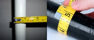
To measure the diameter of the wire, a caliper or micrometer of any type (mechanical or electronic) is suitable. It’s easier to work with electronic ones, but not everyone has them. You need to measure the core itself without insulation, so first move it aside or remove a small piece. This can be done if the seller allows it. If not, buy a small piece to test and take measurements on it. On a conductor stripped of insulation, measure the diameter, after which you can determine the actual cross-section of the wire from the found dimensions.
Measuring wire diameter with a micrometer is more accurate than with a mechanical caliper
Which measuring device is better in this case? If we talk about mechanical models, then a micrometer. Its measurement accuracy is higher. If we talk about electronic options, then for our purposes they both give quite reliable results.
If you don't have a caliper or micrometer, take a screwdriver and a ruler with you. You'll have to strip a fairly decent piece of conductor, so you'll hardly be able to do without buying a test sample this time. So, remove the insulation from a 5-10 cm piece of wire. Wind the wire around the cylindrical part of the screwdriver. Lay the coils close to each other, without a gap. All turns must be complete, that is, the “tails” of the wire must stick out in one direction - up or down, for example.
Determining wire diameter using a ruler
The number of turns is not important - about 10. You can have more or less, it’s just easier to divide by 10. Count the turns, then apply the resulting winding to the ruler, aligning the beginning of the first turn with the zero mark (as in the photo). Measure the length of the section occupied by the wire, then divide it by the number of turns. You get the diameter of the wire. It's that simple.
For example, let's calculate the size of the wire shown in the photo above. The number of turns in this case is 11, they occupy 7.5 mm. Divide 7.5 by 11, we get 0.68 mm. This will be the diameter of this wire. Next, you can look for the cross section of this conductor.
Determination of the conductor cross-section at the input
You can check the nominal values in the Energosbyt company or in the documentation for the product. For example, the input rating of the machine is 25 A, the power consumption is 5 kW, the network is single-phase, 220 V.
The cross-section is selected so that the permissible current of the cores over a long period is greater than the rating of the machine. For example, a three-core copper conductor VVGng, laid in an open manner, was installed in a house. The optimal cross-section is 4 mm2, so you will need VVGng 3x4 material.
After this, the indicator of the conditional shutdown current for a machine with a nominal value of 25 A is calculated: 1.45x25 = 36.25 A. For a cable with a cross-sectional area of 4 mm2, the parameters of the continuous permissible current are 35 A, conditional - 36.25 A. In this case, it is better to take the input copper conductor with a cross-section of 6 mm2 and a permissible maximum current of 42 A.
Calculation of wire cross-section for a line of sockets
Cable cross-section for home electrical installations
Each electrical appliance has its own power ratings. They are measured in Watts and indicated in the passport or on a sticker on the case. An example of searching for a cross section would be a power line for a 2.4 kW washing machine. The calculations take into account:
- wire material and installation method - three-core VVGng copper cable hidden in the wall;
- cross-section features - the optimal value is 1.5 mm2, i.e. you will need a 3x1.5 cable;
- using a socket. If only an automatic machine is connected, the characteristics will be sufficient;
- The protection system is an automatic machine with a rated current of 10 A.
For double sockets, a copper cable with a cross-section of 2.5 mm2 and a 16 A circuit breaker are used.