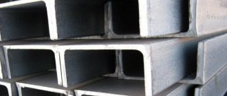
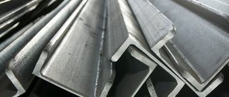
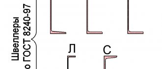
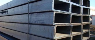
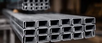
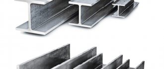
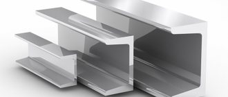
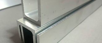
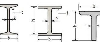
Channel - hot-rolled shaped steel with a box-shaped U-shaped section intended for steel structures, as well as structures with welded and other connections. Channels are manufactured with lengths from 2 to 12 m, by agreement between the consumer and the manufacturer - lengths over 12 m. The weight of the channel varies from 4.79-61.5 kg per linear meter.
The geometric characteristics of the channel section are determined by its number, which corresponds to the height of the channel wall (in centimeters). The channel is used in:
- Powerful rod structures Bridges
- Long span trusses
The geometric characteristics of the channel section are determined by its number, which corresponds to the height of the channel wall (in centimeters). The range includes channels with and without sloped internal edges of the shelves. The slope of the internal edges of the shelves makes design difficult.
The range also includes channels with parallel flange edges, the cross-section of which has the best design characteristics. Such channels are more constructive, since the parallel edges simplify bolting to the shelves.
If it is impossible to use a channel in building structures, you can resort to replacing the channel with an I-beam, or go to another analogue of the profile.
Channels are used in powerful rod structures (places, long-span trusses, etc.), as well as in columns, ties and roof purlins.
Channel
Classification of channels
| No. | Name of channels | Description |
| 1 | Rolled according to GOST 8240-97, DSTU 3436-96 | |
| Steel channel | ||
| 1.1 | Channel. Series U | Channel with a slope of the internal edges of the shelves. Series U. |
| 1.2 | Channel. Series P | Channel with parallel flange edges - P series. |
| 1.3 | Channel. Series E | Economical channel with parallel flange edges - E series. |
| 1.4 | Channel. Series L | Light channel with parallel flange edges - L series. |
| 1.5 | Channel. Series C | Channel with a slope of the inner edges of the shelves - series C. |
| Channel according to the manufacturer's specifications | ||
| 1.6 | Channel according to specifications | |
| Special channel | ||
| 1.7 | Channel. Series C | Channel with a slope of the inner edges of the shelves - series C. |
| Special channel for tractors and carriage building | ||
| 1.8 | Channel | Special channel for tractors and carriage building |
| 2 | Bent channel | |
| 2.1 | Channel according to GOST 8278-83 | Channel. Bent equal flange |
| 2.2 | Channel according to GOST 8281-80 | Channel. Bent unequal |
Table with sizes of special channels.
| Series C channel number | h | b | s | t | R | r | Shelf slope % | Cross-sectional area F cm2 | Weight 1m/kg | Reference values for axes | X0 cm | |||||
| no more | X–X | Y–Y | ||||||||||||||
| mm | Ix cm4 | Wx cm3 | ix cm | Iy cm4 | Wy cm3 | Iy cm | ||||||||||
| 8C | 80 | 45 | 5.5 | 9.0 | 9.0 | 1.5 | 6 | 11.80 | 9.26 | 115.82 | 28.95 | 3.13 | 22.24 | 7.63 | 1.38 | 1.57 |
| 14C | 140 | 58 | 6.0 | 9.5 | 9.5 | 4.75 | – | 18.51 | 14.53 | 563.70 | 80.50 | 5.52 | 53.20 | 13.01 | 1.70 | 1.71 |
| 14Ca | 140 | 60 | 8.0 | 9.5 | 9.5 | 5.0 | 10 | 21.30 | 16.72 | 609.10 | 87.01 | 5.35 | 61.02 | 14.09 | 1.69 | 1.67 |
| 16C | 160 | 63 | 6.5 | 10.0 | 10.0 | 5.0 | – | 21.95 | 17.53 | 866.20 | 108.30 | 6.28 | 73.30 | 16.30 | 1.83 | 1.80 |
| 16Ca | 160 | 65 | 8.5 | 10.0 | 10.0 | 5.0 | – | 25.15 | 19.74 | 934.50 | 116.80 | 6.10 | 83.40 | 17.55 | 1.82 | 1.75 |
| 18C | 180 | 68 | 7.0 | 10.5 | 10.5 | 5.3 | – | 25.70 | 20.20 | 1272.00 | 141.00 | 7.04 | 98.50 | 20.10 | 1.96 | 1.88 |
| 18Ca | 180 | 70 | 9.0 | 10.5 | 10.5 | 5.3 | – | 29.30 | 23.00 | 1370.00 | 152.00 | 6.84 | 111.00 | 21.30 | 1.95 | 1.84 |
| 18Sat | 180 | 100 | 8.0 | 10.5 | 10.5 | 5.0 | 6 | 34.04 | 26.72 | 1791.01 | 199.00 | 7.25 | 305.48 | 43.58 | 3.00 | 2.99 |
| 20C | 200 | 73 | 7.0 | 11.0 | 11.0 | 5.5 | 10 | 28.83 | 22.63 | 1780.37 | 178.04 | 7.86 | 128.04 | 24.19 | 2.11 | 2.02 |
| 20Ca | 200 | 75 | 9.0 | 11.0 | 11.0 | 5.5 | 10 | 32.83 | 25.77 | 1913.71 | 191.37 | 7.64 | 143.63 | 25.88 | 2.09 | 1.95 |
| 20Sat | 200 | 100 | 8.0 | 11.0 | 11.0 | 5.5 | 6 | 36.58 | 28.71 | 2360.88 | 236.09 | 8.03 | 327.23 | 46.30 | 2.99 | 2.93 |
| 24C | 240 | 85 | 9.5 | 14.0 | 14.0 | 7.0 | – | 44.46 | 34.90 | 3841.35 | 320.11 | 9.29 | 268.89 | 43.70 | 2.46 | 2.35 |
| 26C | 260 | 65 | 10.0 | 16.0 | 15.0 | 3.0 | – | 44.09 | 34.61 | 4088.00 | 314.50 | 9.63 | 1115.60 | 171.60 | 5.03 | 3.91 |
| 26Ca | 260 | 90 | 10.0 | 15.0 | 15.0 | 7.5 | 8 | 50.60 | 39.72 | 5130.83 | 394.68 | 10.07 | 343.15 | 52.62 | 2.60 | 2.48 |
| 30C | 300 | 85 | 7.5 | 13.5 | 13.5 | 7.0 | 10 | 43.88 | 34.44 | 6045.43 | 403.03 | 11.74 | 260.74 | 41.41 | 2.44 | 2.20 |
| 30Ca | 300 | 87 | 9.5 | 13.5 | 13.5 | 7.0 | 10 | 49.88 | 39.15 | 6495.43 | 433.03 | 11.41 | 288.78 | 43.93 | 2.41 | 2.13 |
| 30Sat | 300 | 89 | 11.5 | 13.5 | 13.5 | 7.0 | 10 | 55.88 | 43.86 | 6945.43 | 463.03 | 11.15 | 315.35 | 46.29 | 2.38 | 2.09 |
Series C channels are hot-rolled steel channels, which come in general and special purposes and can have the following dimensions: height 50 - 400 mm, shelf width 32 - 15 mm. The dimensions of the C series channel are controlled according to GOST 8240-97.
Examples of the use of channels in construction
Formwork installation
Channel (Strap) – stroyone
Welded metal structures
Channel in welded structure
Traverse from channels - stroyone
Stairs
staircase – stroyone
Stairs – stroyone.com
Channel according to GOST 8240-97
Channel according to GOST 8240-97 – stroyone
Channel (U series) with flange slope
The main parameters (characteristics) of a hot-rolled channel according to GOST 8240-97 with a slope of the internal edges of the flanges are determined by its number, which varies from No. 5 to No. 40. For example, if the channel number is No. 5, its height will correspond to (h) - 50 mm.
Channel U series according to GOST 8240-97
| № | Description |
| 1 | Profile height varies from 50 to 400 (mm) |
| 2 | Shelf width varies from 32 to 115 (mm) |
| 3 | Wall thickness varies from 4.4 to 8 (mm) |
| 4 | Shelf thickness varies from 7 to 13.5 (mm) |
| 5 | Radius varies from 6 to 15 (mm) |
| 6 | Radius varies from 2.5 to 6 (mm) |
| 7 | Cross-sectional area varies from 6.16 to 61.5 (cm²) |
| 8 | Nominal weight of 1 m I-beam, kg varies from 4.84 to 48.3 (kg/m) |
| 9 | Number of running meters per ton varies from 20.704 to 206.612 (p.m/t) |
| 10 | Moment of inertia varies from 22.8 to 15220 (cm⁴) |
| 11 | Moment of resistance varies from 9.1 to 761 (cm³) |
| 12 | Radius of gyration varies from 1.92 to 12 (mm) |
| 13 | Static torque varies from 5.59 to 444 (cm³) |
| 14 | Moment of inertia varies from 5.61 to 327 (cm⁴) |
| 15 | Moment of resistance varies from 2.75 to 43.6 (cm³) |
| 16 | Radius of gyration varies from 1.08 to 3.23 (mm) |
| 17 | The distance to the center of gravity varies from 1.16 to 2.75 (cm) |
Main dimensions of the channel, (U series) with flange slope
| № | Channel no. | h (mm) | B (mm) | S (mm) wall | t (mm) shelf | M (kg/m) | Quantity (m) per ton |
| 1 | Channel 5U | 50 | 32 | 4,4 | 7 | 4,84 | 206,612 |
| 2 | Channel 6.5U | 65 | 36 | 4,4 | 7,2 | 5,9 | 169,492 |
| 3 | Channel 8U | 80 | 40 | 4,5 | 7,4 | 7,05 | 141,844 |
| 4 | Channel 10U | 100 | 46 | 4,5 | 7,6 | 8,59 | 116,414 |
| 5 | Channel 12U | 120 | 52 | 4,8 | 7,8 | 10,4 | 96,154 |
| 6 | Channel 14U | 140 | 58 | 4,9 | 8,1 | 12,3 | 81,301 |
| 7 | Channel 16U | 160 | 64 | 5 | 8,4 | 14,2 | 70,423 |
| 8 | Channel 16аУ | 160 | 68 | 5 | 9 | 15,3 | 65,359 |
| 9 | Channel 18U | 180 | 70 | 5,1 | 8,7 | 16,3 | 61,35 |
| 10 | Channel 18аУ | 180 | 74 | 5,1 | 9,3 | 17,4 | 57,471 |
| 11 | Channel 20U | 200 | 76 | 5,2 | 9 | 18,4 | 54,348 |
| 12 | Channel 22U | 220 | 82 | 5,4 | 9,5 | 21 | 47,619 |
| 13 | Channel 24U | 240 | 90 | 5,6 | 10 | 24 | 41,667 |
| 14 | Channel 27U | 270 | 95 | 6 | 10,5 | 27,7 | 36,101 |
| 15 | Channel 30U | 300 | 100 | 6,5 | 11 | 31,8 | 31,447 |
| 16 | Channel 33U | 330 | 105 | 7 | 11,7 | 36,5 | 27,397 |
| 17 | Channel 36U | 360 | 110 | 7,5 | 12,6 | 41,9 | 23,866 |
| 18 | Channel 40U | 400 | 115 | 8 | 13,5 | 48,3 | 20,704 |
Channel with parallel flanges
The main parameters (characteristics) of a hot-rolled channel according to GOST 8240-97 with parallel flange edges are determined by its number, which varies from No. 5 to No. 40. For example, with channel number No. 40, its height will correspond to (h) - 400 mm.
Channel P series with parallel shelves according to GOST 8240-97
| № | Description |
| 1 | Profile height varies from 50 to 400 (mm) |
| 2 | Profile width varies from 32 to 115 (mm) |
| 3 | Wall thickness varies from 4.5 to 8 (mm) |
| 4 | Shelf thickness varies from 7 to 13.5 (mm) |
| 5 | Radius varies from 6 to 14 (mm) |
| 6 | Radius varies from 3.5 to 9 (mm) |
| 7 | Cross-sectional area varies from 6.16 to 61.5 (cm²) |
| 8 | Nominal weight of 1 m I-beam, kg varies from 4.84 to 48.3 (kg/m) |
| 9 | Number of running meters per ton varies from 0.023 to 206.612 (p.m/t) |
| 10 | Moment of inertia varies from 22.8 to 15260 (cm⁴) |
| 11 | Moment of resistance varies from 9.1 to 763 (cm³) |
| 12 | Radius of gyration varies from 1.92 to 15.8 (mm) |
| 13 | Static torque varies from 5.61 to 445 (cm³) |
| 14 | Moment of inertia varies from 5.95 to 611 (cm⁴) |
| 15 | Moment of resistance varies from 2.99 to 89.9 (cm³) |
| 16 | Radius of gyration varies from 0.98 to 3.51 (mm) |
| 17 | The distance to the center of gravity varies from 1.21 to 3.05 (cm) |
Main dimensions of the channel, (P series) with parallel flanges
| № | Channel no. | h (mm) | B (mm) | S (mm) wall | t (mm) shelf | M (kg/m) | Quantity (m) per ton |
| 1 | Channel 5P | 50 | 32 | 4.4 | 7 | 6,16 | 4,84 |
| 2 | Channel 6.5P | 65 | 36 | 4.4 | 7.2 | 7,51 | 5,9 |
| 3 | Channel 8P | 80 | 40 | 4,5 | 7,4 | 8,98 | 7.05 |
| 4 | Channel 10P | 100 | 46 | 4,5 | 7,6 | 10,9 | 8,59 |
| 5 | Channel 12P | 120 | 52 | 4,8 | 7,8 | 13,3 | 10,4 |
| 6 | Channel 14P | 140 | 58 | 4,9 | 8,1 | 15,6 | 12,3 |
| 7 | Channel 16P | 160 | 64 | 5.0 | 8.4 | 18,1 | 14,2 |
| 8 | Channel 16aP | 160 | 68 | 5 | 9 | 19.50 | 15,3 |
| 9 | Channel 18P | 180 | 70 | 5,1 | 8,7 | 20,7 | 16,3 |
| 10 | Channel 18aP | 180 | 74 | 5,1 | 9,3 | 22,2 | 17,4 |
| 11 | Channel 20P | 200 | 76 | 5.2 | 9.0 | 23,4 | 18,4 |
| 12 | Channel 22P | 220 | 82 | 5.4 | 9.5 | 26,7 | 21 |
| 13 | Channel 24P | 240 | 90 | 5.6 | 10 | 30,6 | 24 |
| 14 | Channel 27P | 270 | 95 | 6 | 10,5 | 35,2 | 27,7 |
| 15 | Channel 30P | 300 | 100 | 6,5 | 11 | 40,5 | 31,8 |
| 16 | Channel 33P | 330 | 105 | 7 | 11,7 | 46,5 | 36,5 |
| 17 | Channel 36P | 360 | BY | 7.5 | 12,6 | 53,4 | 41,9 |
| 18 | Channel 40P | 400 | 115 | 8 | 13,5 | 61,5 | 48,3 |
Economical channel with parallel flange edges
The main parameters (characteristics) of an economical hot-rolled channel with parallel flanges in accordance with GOST 8240-97 are determined by its number, which varies from No. 5 to No. 40. For example, if the channel number is No. 5, its height will correspond to (h) - 50 mm.
Channel E series with parallel shelves according to GOST 8240-97
| № | Description |
| 1 | Profile height varies from 50 to 400 (mm) |
| 2 | Profile width varies from 32 to 115 (mm) |
| 3 | Wall thickness varies from 4.2 to 7.4 (mm) |
| 4 | Shelf thickness varies from 7 to 13.5 (mm) |
| 5 | Radius varies from 6.5 to 15.5 (mm) |
| 6 | Radius varies from 2.5 to 6 (mm) |
| 7 | Cross-sectional area varies from 6.1 to 61.11 (cm²) |
| 8 | Nominal weight of 1 m I-beam, kg varies from 4.79 to 47.97 (kg/m) |
| 9 | Number of running meters per ton varies from 20.846 to 208.768 (p.m/t) |
| 10 | Moment of inertia varies from 22.9 to 15307.9 (cm⁴) |
| 11 | Moment of resistance varies from 9.17 to 603.58 (cm³) |
| 12 | Radius of gyration varies from 1.94 to 15.83 (mm) |
| 13 | Static torque varies from 5.62 to 445.41 (cm³) |
| 14 | Moment of inertia varies from 6.02 to 618.92 (cm⁴) |
| 15 | Moment of resistance varies from 3.05 to 91.8 (cm³) |
| 16 | Radius of gyration varies from 0.993 to 3.42 (mm) |
| 17 | The distance to the center of gravity varies from 1.23 to 3.04 (cm) |
Main dimensions of economical channel (E series) with parallel flanges
| № | Channel no. | h (mm) | B (mm) | S (mm) wall | t (mm) shelf | M (kg/m) | Quantity (m) per ton |
| 1 | Channel 5E | 50 | 32 | 4,2 | 7 | 4,79 | 208,768 |
| 2 | Channel 6.5E | 65 | 36 | 4,2 | 7,2 | 5,82 | 171,821 |
| 3 | Channel 8E | 80 | 40 | 4,2 | 7,4 | 6,92 | 144,509 |
| 4 | Channel 10E | 100 | 46 | 4,2 | 7.6 | 8,47 | 118,064 |
| 5 | Channel 12E | 120 | 52 | 4,5 | 7.8 | 10,24 | 97,656 |
| 6 | Channel 14E | 140 | 58 | 4.6 | 8.1 | 12,15 | 82,305 |
| 7 | Channel 16E | 160 | 64 | 4,7 | 8,4 | 14,01 | 71,378 |
| 8 | Channel 18E | 180 | 70 | 4,8 | 8,7 | 16,01 | 62,461 |
| 9 | Channel 20E | 200 | 76 | 4,9 | 9 | 18,07 | 55,34 |
| 10 | Channel 22E | 220 | 82 | 5,1 | 9.5 | 20,69 | 48,333 |
| 11 | Channel 24E | 240 | 90 | 5.3 | !0,0 | 23,69 | 42,212 |
| 12 | Channel 27E | 270 | 95 | 5,8 | 10,5 | 27,37 | 36,536 |
| 13 | Channel 30E | 300 | 100 | 6,3 | 11 | 31,35 | 31,898 |
| 14 | Channel 33E | 330 | 105 | 6,9 | 11,7 | 36,14 | 27,67 |
| 15 | Channel 36E | 360 | 110 | 7,4 | 12,6 | 41,53 | 24,079 |
| 16 | Channel 40E | 400 | 115 | 7.9 | 13,5 | 47,97 | 20,846 |
Light channel with parallel flange edges, L series (light)
The main parameters (characteristics) of a light hot-rolled channel according to GOST 8240-97 with parallel flange edges are determined by its number, which varies from No. 12 to No. 30. For example, with channel number No. 30, its height will correspond to (h) - 300 mm.
Channel L series (lightweight) with parallel shelves according to GOST 8240-97
| № | Description |
| 1 | Profile height varies from 120 to 300 (mm) |
| 2 | Profile width varies from 30 to 65 (mm) |
| 3 | Wall thickness varies from 3 to 4.8 (mm) |
| 4 | Shelf thickness varies from 4.8 to 7.8 (mm) |
| 5 | Radius varies from 7 to 11 (mm) |
| 6 | Cross-sectional area varies from 6.39 to 24.3 (cm²) |
| 7 | Nominal weight of 1 m I-beam, kg varies from 5.94 to 19.07 (kg/m) |
| 8 | Number of running meters per ton varies from 0.023 to 168.35 (p.m/t) |
| 9 | Moment of inertia varies from 212.94 to 3186.74 (cm⁴) |
| 10 | Moment of resistance varies from 22.54 to 212.45 (cm³) |
| 11 | Radius of gyration varies from 4.6 to 11.45 (mm) |
| 12 | Static moment varies from 13.43 to 126.24 (cm³) |
| 13 | Moment of inertia varies from 5.02 to 89.08 (cm⁴) |
| 14 | Moment of resistance varies from 2.24 to 17.84 (cm³) |
| 15 | Radius of gyration varies from 0.89 to 1.91 (mm) |
| 16 | The distance to the center of gravity varies from 0.7 to 1.5 (cm) |
Main dimensions of a light channel (L series) with parallel flanges
| № | Channel no. | h (mm) | B (mm) | S (mm) wall | t (mm) shelf | M (kg/m) | Quantity (m) per ton |
| 1 | Channel 12L | 120 | 30 | 3 | 4,8 | 5.02 | 0,023 |
| 2 | Channel 14L | 140 | 32 | 3,2 | 5,6 | 5,94 | 168,35 |
| 3 | Channel 16L | 160 | 35 | 3,4 | 5,3 | 7,1 | 140,845 |
| 4 | Channel 18L | 180 | 40 | 3,6 | 5,6 | 8,49 | 117,786 |
| 5 | Channel 20L | 200 | 45 | 3,8 | 6 | 10,12 | 98,814 |
| 6 | Channel 22L | 220 | 50 | 4 | 6,4 | 11,86 | 84,317 |
| 7 | Channel 24L | 240 | 55 | 4,2 | 6,8 | 13,66 | 73,206 |
| 8 | Channel 27L | 270 | 60 | 4,5 | 7,3 | 16,3 | 61,35 |
| 9 | Channel 30L | 300 | 65 | 4,8 | 7,8 | 19,07 | 52,438 |
Special channel - series C
The main parameters (characteristics) of a special channel (series C) according to GOST 8240-97 hot-rolled with parallel flange edges are determined by its number, which varies from No. 8 to No. 30. For example, with channel number No. 30, its height will correspond to (h) - 300 mm.
Channel series C (special) according to GOST 8240-97
| № | Description |
| 1 | Profile height varies from 80 to 300 (mm) |
| 2 | Profile width varies from 45 to 100 (mm) |
| 3 | Wall thickness varies from 2.5 to 11.5 (mm) |
| 4 | Shelf thickness varies from 9 to 16 (mm) |
| 5 | Radius varies from 9 to 15 (mm) |
| 6 | Radius varies from 1.5 to 7.5 (mm) |
| 7 | The slope of the shelves varies from 6 to 10 (%) |
| 8 | Cross-sectional area varies from 11.8 to 50.6 (cm²) |
| 9 | Nominal weight of 1 m I-beam, kg varies from 9.26 to 43.86 (kg/m) |
| 10 | Number of running meters per ton varies from 22.8 to 107.991 (p.m/t) |
| 11 | Moment of inertia varies from 115.82 to 6945.43 (cm⁴) |
| 12 | Moment of resistance varies from 28.95 to 463.03 (cm³) |
| 13 | Radius of gyration varies from 3.13 to 11.74 (mm) |
| 14 | Moment of inertia varies from 53.2 to 1115.6 (cm⁴) |
| 15 | Moment of resistance varies from 7.63 to 171.6 (cm³) |
| 16 | Radius of gyration varies from 1.38 to 5.03 (mm) |
| 17 | Distance to center of gravity varies from 1.57 to 3.91 (cm) |
Main dimensions of special channel (series C)
| № | Channel no. | h (mm) | B (mm) | S (mm) wall | t (mm) shelf | M (kg/m) | Quantity (m) per ton |
| 1 | Channel 8C | 80 | 45 | 5,5 | 9 | 9,26 | 107,991 |
| 2 | Channel 14C | 140 | 58 | 6 | 9.5 | 14,53 | 68,823 |
| 3 | Channel 14Са | 140 | 60 | 8 | 9,5 | 16,72 | 59,809 |
| 4 | Channel 16C | 160 | 63 | 6,5 | 10 | 17,53 | 57,045 |
| 5 | Channel 16Са | 160 | 65 | 8,5 | 10 | 19,74 | 50,659 |
| 6 | Channel 18C | 180 | 68 | 7 | 10,5 | 20,2 | 49,505 |
| 7 | Channel 18Са | 180 | 70 | 9.0 | 10,5 | 23 | 43,478 |
| 8 | Channel 18S6 | 180 | 100 | 8 | 10,5 | 26,72 | 37,425 |
| 9 | Channel 20C | 200 | 73 | 7 | 11 | 22,63 | 44,189 |
| 10 | Channel 20Са | 200 | 75 | 9 | 11 | 25,77 | 38,805 |
| 11 | Channel 20S6 | 200 | 100 | 8 | 11 | 28,71 | 34,831 |
| 12 | Channel 24C | 240 | 85 | 9.5 | 14 | 34,9 | 28,653 |
| 13 | Channel 26C | 260 | 65 | 10 | 16 | 34,61 | 28,893 |
| 14 | Channel 26Са | 260 | 90 | 10 | 15 | 39,72 | 25,176 |
| 15 | Channel 30C | 300 | 85 | 2,5 | 13,5 | 34,44 | 29,036 |
| 16 | Channel 30Са | 300 | 87 | 9,5 | 13,5 | 39,15 | 25,543 |
| 17 | Channel 30Sb | 300 | 89 | 11,5 | 13,5 | 43,86 | 22,8 |
Table with dimensions of light series channels with parallel flange edges.
| Series L channel number | h | b | s | t | R | r | Cross-sectional area F cm2 | Weight 1m/kg | Reference values for axes | X0cm | ||||||
| no more | X–X | Y–Y | ||||||||||||||
| mm | Ix cm4 | Wx cm3 | Ix cm | Sx cm3 | Iy cm4 | Wy cm3 | i0 cm | |||||||||
| 12L | 120 | 30 | 3.0 | 4.8 | 7 | – | 6.39 | 5.02 | 135.26 | 22.54 | 4.60 | 13.43 | 5.02 | 2.24 | 0.89 | 0.76 |
| 14L | 140 | 32 | 3.2 | 5.6 | 7 | – | 7.57 | 5.94 | 212.94 | 30.42 | 5.31 | 18.23 | 6.55 | 2.70 | 0.93 | 0.78 |
| 16L | 160 | 35 | 3.4 | 5.3 | 8 | – | 9.04 | 7.10 | 331.96 | 41.49 | 6.06 | 24.84 | 9.23 | 3.46 | 1.01 | 0.83 |
| 18L | 180 | 40 | 3.6 | 5.6 | 8 | – | 10.81 | 8.49 | 503.87 | 55.98 | 6.83 | 33.49 | 14.64 | 4.10 | 1.16 | 0.94 |
| 20L | 200 | 45 | 3.8 | 6.0 | 9 | – | 12.89 | 10.12 | 748.17 | 74.82 | 7.62 | 44.59 | 22.37 | 6.51 | 1.32 | 1.06 |
| 22L | 220 | 50 | 4.0 | 6.4 | 10 | – | 15.11 | 11.86 | 1070.97 | 97.36 | 8.42 | 57.82 | 32.85 | 8.61 | 1.47 | 1.19 |
| 24L | 240 | 55 | 4.2 | 6.8 | 10 | – | 17.41 | 13.66 | 1476.39 | 123.03 | 9.21 | 72.90 | 46.25 | 11.04 | 1.63 | 1.31 |
| 27L | 270 | 60 | 4.5 | 7.3 | 11 | – | 20.77 | 16.30 | 2218.16 | 164.31 | 10.33 | 97.48 | 65.10 | 14.17 | 1.77 | 1.40 |
| 30L | 300 | 65 | 4.8 | 7.8 | 11 | – | 24.30 | 19.07 | 3186.74 | 212.45 | 11.45 | 126.24 | 89.08 | 17.84 | 1.91 | 1.51 |
Series L channels must have a wall deflection size of no more than 0.15s.
