What the article is about:
Why does a semi-automatic cook poorly and what can be done?
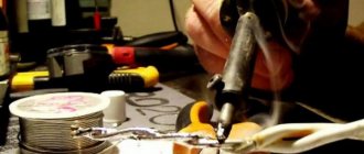
Often, when welding with a semi-automatic welding machine, the seam turns out to be bad, and the wire every now and then sticks to the metal. If there are no current clamps to check the amperage, then you can try changing the welding gas or using a wire of a smaller diameter.
Very often it is Chinese semi-automatic machines that suffer from this problem. These machines just don’t want to produce the welding current declared by the manufacturer, and then you have to work around the instructions.
Why does a semi-automatic cook poorly? What can be done?
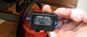
First of all, try to measure the voltage, set it to maximum and wire feed to minimum. Very often, a lot depends on the voltage in the garage. If it is less than 220 Volts, then a bad Chinese semi-automatic machine will not cook properly. More precisely, it will try to heat the welding wire, but it will remain stuck to the metal, only turning a little red.
It’s also worth checking exactly what polarity is set. In addition, it would be a good idea to look at exactly where the wires are connected. Very often, novice welders make mistakes precisely at the stage of connecting a semi-automatic machine. As a result of this, they connect the wires to the welding mode “without gas” and try to weld with carbon dioxide.
What gas should I use?
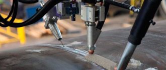
The type of shielding gas affects the welding characteristics: penetration depth, electric arc and mechanical properties of the weld.
p, blockquote 8,0,0,0,0 –>
- 100% carbon dioxide (most often used for welding steels) provides deeper penetration when welding, but increases the amount of spatter and the weld is rougher than with a mixture of argon and carbon dioxide.
- A mixture of 75% argon and 25% carbon dioxide (called 75/25 or C25) can be considered the best mixture for carbon steel. When welding with such a gas, little spatter is generated, a beautiful seam is obtained, and during welding thin metal is not burned through, since there is no strong penetration.
- To weld stainless steel, a mixture of 98% argon and 2% carbon dioxide is used. For aluminum – 100% argon.
Problems when welding with cored wire
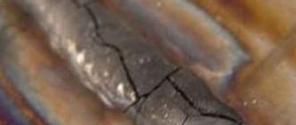
Flux-cored wire welding is in demand in cases where there is no gas. But, as it turns out, from time to time, various kinds of problems arise with it. The most common problem is that the semi-automatic machine “spits” and does not weld the metal well or does not weld it at all. The cored wire simply sticks to the surface of the metal and leaves scale on it.
First of all, you need to return to all the previous reasons. That is, check the voltage in the network, play with the settings, change the polarity, and, of course, thoroughly study the instructions of the manufacturer of the semi-automatic welding machine. Perhaps it is in it that you will be able to find those numerous answers to your questions. You should never be lazy and just put the instructions aside.
So, there can be several problems when a semi-automatic welding machine “spits”:
- Firstly, wire jamming;
- Secondly, bad gas;
- Thirdly, the wire is unsuitable for welding or the polarity is incorrectly set;
- Fourthly, there is no or poor contact of the wire with the torch nose;
- Problems with the supply voltage or welding current.
However, most often the problem turns out to be unsuitable or poor quality welding wire. Therefore, before repairing a semi-automatic machine, you should first try to change the wire to another, more expensive and high-quality one. If this is the case, then the semi-automatic machine will cook like new.
Well, of course, if you have this problem, it’s worth trying to completely turn off the gas. If the problem does not go away, that is, the semiautomatic device continues to spit, then you need to look for a solution elsewhere.
Thank you all for your attention. The site “Semi-automatic welding” was with you. Subscribe, like, and have a nice weekend. Bye bye.
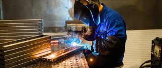
Spattering during manual arc welding with coated electrodes
This determines the following advantages of manual arc welding with coated electrodes compared to mechanized arc welding methods:
— the ability to weld in very inconvenient and difficult to access mechanized welding methods;
— simplicity and low cost of equipment compared to mechanized welding methods;
— the ability to monitor the welding process and high maneuverability of the process, ensuring the execution of short and long seams of any shape in various spatial positions;
— welding with coated electrodes allows you to obtain weld metal of almost any composition due to alloying through the coating without expanding the range of wire;
- is the main method of welding in field conditions during the installation of main and field pipelines, despite the existing proven mechanized methods of welding in shielding gases.
However, along with the advantages, this welding method has disadvantages that reduce the effectiveness of its use: low productivity compared to mechanized welding methods; dependence of the quality of the welded joint on the qualifications of the welder; different rates of melting of the electrode at the beginning and end of the process (since the current flowing through the electrode heats it up and the resistance changes); large losses of metal due to waste and spattering, cinders, in total amounting to 10-20% of the mass of the rod.
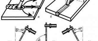
The main reasons for the ejection of metal droplets from the welding zone include:
— unstable nature of metal transfer, when the force separating a drop from the electrode is directed away from the bath and the drop is thrown beyond its boundaries; transfer instability can be caused by the conditions of arc discharge development and metallurgical factors, in particular the intense occurrence of chemical reactions;
- local explosive release of gases in the volume of metal, caused by metallurgical reactions and leading to the release of metal particles from drops or, less commonly, from the bath;
— destruction of the bridge of liquid metal formed during the transfer of metal with short circuits as a result of a sharp increase in current density when the bridge narrows; spattering largely depends on the dynamic characteristics of the current source;
— insufficient stability of the welding process.
The intensity of metal spattering depends on many factors:
— type of electrode coating (constituent components of the electrode coating) and the condition of the surface of the base metal edges;
— characteristics of the power source (the work has established a relationship between the dynamic characteristics of the power source and losses due to spattering of the electrode metal);
- values and ratios of welding mode parameters, etc.
There are no exact data on the magnitude of spatter during manual arc welding with coated electrodes. We can only divide the existing brands of electrode coatings into three groups: with large, moderate and small spatter. Thus, there is clearly insufficient data on the issue of spatter during manual arc welding with coated electrodes.
This paper presents a research methodology for determining the loss of electrode metal due to waste and spattering during manual arc welding with coated electrodes.
Losses due to waste and spattering are determined by the formula
where Qp is the amount of molten electrode metal, g; Qn - amount of deposited electrode metal, g.
A quantitative indicator of metal spattering is the spattering coefficient Ψ, which represents the ratio of the mass of splashes to the mass of molten metal of the electrode:
In this work, the influence of the brand (composition) of the electrode and welding current on the size and amount of spattered electrode metal was investigated. A VDU-306 UZ rectifier was used as a power source. Welding was carried out in a box to facilitate the collection of splashes.
All resulting splashes were divided into three fractions: with a diameter of 1.6 mm or more, 1-1.6 mm and less than 1 mm. The results of the studies are shown in Fig. 1.
Spattering of electrode metal is accompanied by its splashing onto the surface of the parts being welded during manual arc welding and can reach significant values (see table).
According to the results of studies conducted to determine the complexity of cleaning the surface of welded products from splashes of molten metal, it was found that when welding with electrodes with a diameter of 3 mm, the time for cleaning (manually using a chisel and hammer) is 35% of the welding time, and with electrodes with a diameter of 4 mm - 42 %.
Therefore, the problem of combating spatter during manual arc welding with coated electrodes is no less relevant than during mechanized welding in CO2.
There are two ways to reduce the amount of droplets of molten metal splashed onto the surface of the parts being welded:
— eliminate or reduce the amount of spatter (by developing metal transfer control systems or new welding materials, technologies and welding techniques);
— the use of coatings to protect the surface of the metal being welded from splashes of molten metal.
In Fig. Table 2 shows the results of experimental studies to determine the amount of spatter (the mass of hard-to-remove droplets from the surface of welded parts) during manual arc welding with coated electrodes with and without the use of a protective coating. The experimental procedure was as follows: two plates were welded with coated electrodes with and without applying a protective coating; easily removed drops were collected from the surface of the welded products using a brush, and difficult to remove drops were collected mechanically; The mass of collected and cut droplets was determined by weighing. Protective coatings No. 1 (Patent 2297311 (RF)) and 2 (caustic soda, CBJ, water) were used (see Fig. 2).
Rice. 2. Dependence of the amount of spatter on the welding current during manual arc welding with electrodes UONI-13/45 (a), OK 53.70 (b), LV-52 (c), MR-3 (d) and MR-3 (ESAB) (e) (light columns - uncoated, dark - coating No. 1, white - coating No. 2)
Let's compare drops of molten metal when welding in carbon dioxide and manual arc welding. A drop of molten metal during manual arc welding can be covered with both a protective layer of molten slag and oxides of molten iron - FeO, Fe2O3, Fe3O4, and when welding in carbon dioxide - a drop without coating.
It has been established that the presence of an oxide film and contaminants on the surface of the metal being welded reduces the adhesion strength of the drop to the surface of the product being welded. Consequently, the presence of an intermediate layer between the drop and the surface of the welded product affects their adhesion strength. It is possible to use protective coatings as an intermediate layer during manual arc welding.
1. When determining the losses of electrode metal due to waste and spatter during manual arc welding with coated electrodes of various brands, a relationship was established between the amount of losses and the welding current, which made it possible to select rational welding modes with minimal losses of electrode metal.
2. It has been established that difficult-to-remove splashes are located at a distance not exceeding 40 mm from the joint line.
3. The use of protective coatings of various compositions makes it possible to reduce spattering by more than 2 times, while to effectively protect the surface from splashes, the coating must be applied at least 40 mm from the joint line.
source
Examples of welds with different voltage settings
The voltage determines the height and width of the weld.
p, blockquote 21,0,0,0,0 –>
The photo shows welds on 1.2 mm thick sheet metal made with increasing stress (from left to right). Seams made on low settings turned out narrow and tall, while on high settings they turned out wide and flat.
p, blockquote 22,0,0,0,0 –>
The photo on the left shows seams on sheet metal made under increasing stress. From left to right from lower voltage to higher voltage. In the second photo, the reverse side of the sheet shows penetration (penetration).
If you look from the reverse side, the two seams on the left did not have good penetration (welding) along the entire length. The three seams on the right have good penetration along the entire length.
p, blockquote 23,0,0,0,0 –>
Welding seams in section
These seams in cross-section show the effect of increasing stress more clearly. On the first two there is a seam at the top, but it did not penetrate the metal at all. The third one has both a top seam and good penetration and is the best seam of all. The two seams on the right have more penetration under the sheet than on top because the tension settings are too high.
p, blockquote 24,0,0,0,0 –>