ESKD requirements for the designation of switches
The designation on the circuit breaker diagram is quite clear. It is prescribed in the ESKD, and foreign metric systems are prescribed in accordance with the ISO standard. Moreover, the designation of switches in both of these systems is almost identical. But, as usual, there are also some nuances, to which we will draw your attention in this article.
Regulations
Taking into account the large number of electrical elements, a number of normative documents have been developed for their alphanumeric (hereinafter referred to as BO) and conventional graphic designations (UGO) to eliminate discrepancies. Below is a table showing the main standards.
Table 1. Standards for graphic designation of individual elements in installation and circuit diagrams.
| GOST number | Short description |
| 2.710 81 | This document contains GOST requirements for BO of various types of electrical elements, including electrical appliances. |
| 2.747 68 | Requirements for the dimensions of displaying elements in graphical form. |
| 21.614 88 | Accepted codes for electrical and wiring plans. |
| 2.755 87 | Display of switching devices and contact connections on diagrams |
| 2.756 76 | Standards for sensing parts of electromechanical equipment. |
| 2.709 89 | This standard regulates the standards in accordance with which contact connections and wires are indicated on diagrams. |
| 21.404 85 | Schematic symbols for equipment used in automation systems |
It should be taken into account that the element base changes over time, and accordingly changes are made to regulatory documents, although this process is more inert. Let's give a simple example: RCDs and automatic circuit breakers have been widely used in Russia for more than a decade, but there is still no single standard according to GOST 2.755-87 for these devices, unlike circuit breakers. It is quite possible that this issue will be resolved in the near future. To keep abreast of such innovations, professionals monitor changes in regulatory documents; amateurs do not have to do this; it is enough to know the decoding of the main symbols.
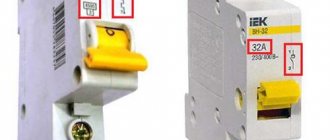
Single pole switches
In many cases, devices with only one module are used .
In such modifications, copper conductors. It is important to know that they should be used to service generators whose operating frequency range is not higher than 20 Hz. There are also certain disadvantages that are taken into account when choosing. An important nuance: the maximum load during use should not exceed 200 A. Therefore, they are not installed in residential buildings where there is significant electricity consumption. Another feature: low output voltage, mostly 200 V.
Types of electrical circuits
In accordance with ESKD standards, diagrams mean graphic documents on which, using accepted notations, the main elements or components of a structure, as well as the connections connecting them, are displayed. According to the accepted classification, there are ten types of circuits, of which three are most often used in electrical engineering:
- Functional, it shows the node elements (depicted as rectangles), as well as the communication lines connecting them. A characteristic feature of this scheme is minimal detail. To describe the main functions of nodes, the rectangles displaying them are signed with standard letter designations. These can be various parts of the product that differ in functionality, for example, an automatic dimmer with a photo relay as a sensor or a regular TV. An example of such a scheme is presented below.
Example of a functional diagram of a television receiver - Fundamental. This type of graphic document displays in detail both the elements used in the design and their connections and contacts. The electrical parameters of some elements can be displayed directly in the document, or presented separately in the form of a table.
Example of a circuit diagram of a milling machine
If the diagram shows only the power part of the installation, then it is called single-line; if all elements are shown, then it is called complete.
Single Line Diagram Example
- Electrical wiring diagrams. These documents use positional designations of elements, that is, their location on the board, method and order of installation are indicated.
Installation diagram of a stationary flammable gas detector
If the drawing shows the wiring of the apartment, then the locations of lighting fixtures, sockets and other equipment are indicated on the plan. Sometimes you can hear such a document called a power supply diagram; this is incorrect, since the latter shows how consumers are connected to a substation or other power source.
Having dealt with the electrical circuits, we can move on to the designations of the elements indicated on them.
Installation recommendations
To use the device safely and correctly, the following recommendations must be observed:
- The device must be installed indoors;
- the device must be protected from moisture, as well as from bad climatic conditions;
- the required operating environment temperature for the device ranges from -40 to +55 degrees;
- if the upper part of the contact knife burns, it is necessary to clean it with a file;
- It is necessary that the device is securely and firmly installed.
If the changeover switch is installed outdoors, then it is necessary to ensure protection from environmental influences. It is also necessary to ensure that the device operates within the permissible temperature range - that is, if outdoors, then it is necessary to ensure heating of the cabinet where this switch is installed. Installation, maintenance and repair of the device should only be carried out by a specialist, and only when the power supply is completely disconnected.
Finally, we recommend watching a video that explains in more detail how to connect a changeover switch to the network:
It will be useful to read:
- How to install a diesel generator
- How to connect a three-phase voltage stabilizer
- Connecting the generator to the home network
- What is a load switch used for?
A changeover switch is a special device designed to switch electricity to the necessary devices, operating using a manual drive. Manufacturers offer a wide range of such devices, differing in various technical characteristics.
It is important to remember that there are various options for connecting changeover switches - the choice depends on the characteristics of the electrical network. The most popular switch type switches in residential buildings
To change the operating characteristics of such devices, control units are used.
In addition, these devices have found application in industry when operating backup generators. When choosing a changeover switch for a generator, you need to take into account its configuration and the specifics of the existing grounding.
The quality of operation of the device is ensured by equipping it with a grounding electrode. Its marking indicates the degree of protection. It is optimal if it is IP30.
Graphic symbols
Each type of graphic document has its own designations, regulated by relevant regulatory documents. Let us give as an example the basic graphic symbols for different types of electrical circuits.
Examples of UGO in functional diagrams
Below is a picture depicting the main components of automation systems.
Examples of symbols for electrical appliances and automation equipment in accordance with GOST 21.404-85
Description of symbols:
- A – Basic (1) and acceptable (2) images of devices that are installed outside the electrical panel or junction box.
- B - The same as point A, except that the elements are located on the remote control or electrical panel.
- C – Display of actuators (AM).
- D – Influence of MI on the regulating body (hereinafter referred to as RO) when the power is turned off:
- RO opening occurs
- Closing RO
- The position of the RO remains unchanged.
- E – IM, on which a manual drive is additionally installed. This symbol may be used for any RO provisions specified in paragraph D.
- F- Accepted mappings of communication lines:
- General.
- There is no connection at the intersection.
- The presence of a connection at the intersection.
Read also: Repair of asynchronous electric motors with a wound rotor
UGO in single-line and complete electrical circuits
There are several groups of symbols for these schemes; we present the most common of them. To obtain complete information, you must refer to the regulatory documents; the numbers of state standards will be given for each group.
Power supplies.
To designate them, the symbols shown in the figure below are used.
UGO power supplies on schematic diagrams (GOST 2.742-68 and GOST 2.750.68)
Description of symbols:
- A is a constant voltage source, its polarity is indicated by the symbols “+” and “-”.
- B – electricity icon indicating alternating voltage.
- C is a symbol of alternating and direct voltage, used in cases where the device can be powered from any of these sources.
- D – Display of battery or galvanic power supply.
- E- Symbol of a battery consisting of several batteries.
Communication lines
The basic elements of electrical connectors are presented below.
Designation of communication lines on circuit diagrams (GOST 2.721-74 and GOST 2.751.73)
Description of symbols:
- A – General display adopted for various types of electrical connections.
- B – Current-carrying or grounding bus.
- C – Designation of shielding, can be electrostatic (marked with the symbol “E”) or electromagnetic (“M”).
- D – Grounding symbol.
- E – Electrical connection with the device body.
- F - On complex diagrams, consisting of several components, a broken connection is thus indicated; in such cases, “X” is information about where the line will be continued (as a rule, the element number is indicated).
- G – Intersection with no connection.
- H – Joint at intersection.
- I – Branches.
Designations of electromechanical devices and contact connections
Examples of the designation of magnetic starters, relays, as well as contacts of communication devices can be seen below.
UGO adopted for electromechanical devices and contactors (GOSTs 2.756-76, 2.755-74, 2.755-87)
Description of symbols:
- A – symbol of the coil of an electromechanical device (relay, magnetic starter, etc.).
- B – UGO of the receiving part of the electrothermal protection.
- C – display of the coil of a device with mechanical interlock.
- D – contacts of switching devices:
- Closing.
- Disconnecting.
- Switching.
- E – Symbol for designating manual switches (buttons).
- F – Group switch (switch).
UGO of electric machines
Let us give several examples of displaying electrical machines (hereinafter referred to as EM) in accordance with the current standard.
Designation of electric motors and generators on circuit diagrams (GOST 2.722-68)
Description of symbols:
- A – three-phase EM:
- Asynchronous (squirrel-cage rotor).
- The same as point 1, only in a two-speed version.
- Asynchronous electric motors with phase-phase rotor design.
- Synchronous motors and generators.
- B – Collector, DC powered:
- EM with permanent magnet excitation.
- EM with excitation coil.
Designation of electric motors on diagrams
UGO transformers and chokes
Examples of graphic symbols for these devices can be found in the figure below.
Correct designations of transformers, inductors and chokes (GOST 2.723-78)
Description of symbols:
- A – This graphic symbol can indicate inductors or windings of transformers.
- B – Choke, which has a ferrimagnetic core (magnetic core).
- C – Display of a two-coil transformer.
- D – Device with three coils.
- E - Autotransformer symbol.
- F – Graphic display of CT (current transformer).
Designation of measuring instruments and radio components
A brief overview of the UGO of these electronic components is shown below. For those who want to become more familiar with this information, we recommend viewing GOSTs 2.729 68 and 2.730 73.
Examples of graphic symbols for electronic components and measuring instruments
Description of symbols:
- Electricity meter.
- Picture of an ammeter.
- Device for measuring network voltage.
- Thermal sensor.
- Fixed value resistor.
- Variable resistor.
- Capacitor (general designation).
- Electrolytic capacity.
- Diode designation.
- Light-emitting diode.
- Image of a diode optocoupler.
- UGO transistor (in this case npn).
- Fuse designation.
UGO lighting devices
Let's look at how electric lamps are displayed on a circuit diagram.
An example of how light bulbs are indicated on diagrams (GOST 2.732-68)
Description of symbols:
- A – General image of incandescent lamps (LN).
- B – LN as a signaling device.
- C – Typical designation of gas-discharge lamps.
- D – High-pressure gas-discharge light source (the figure shows an example of a design with two electrodes)
Designation of elements in the electrical wiring diagram
Concluding the topic of graphic symbols, we give examples of displaying sockets and switches.
An example of an image on the wiring diagrams of flush-mounted sockets
How sockets of other types are depicted is easy to find in the regulatory documents that are available on the Internet.
Designation of flush-mounted switches
Designation of sockets and switches
Selecting ATS
The table below will help you decide on the type of ATS.
Table 1
| ATS type | Device Features | Action |
| Single acting | Two sections. One working and one backup | Connects a backup line in case of power failure on the main one |
| Double acting | Sections are equivalent | You can connect any line, regardless of voltage availability |
| With restoration | Monitors the presence of voltage at the main input after switching to backup power | When voltage appears on the main line, it transfers the circuit (with a slight delay) to its original state |
| No recovery | Switches sections after voltage loss at the main input | Operator intervention is required to switch to main mode |
Letter designations
In electrical diagrams, in addition to graphic symbols, alphabetic symbols are also used, since without the latter, reading the drawings will be quite problematic. Alphanumeric marking, just like UGO, is regulated by regulatory documents, for electrical this is GOST 7624 55. Below is a table with BO for the main components of electrical circuits.
Letter designations of main elements
Unfortunately, the size of this article does not allow us to provide all the correct graphic and letter symbols, but we have indicated regulatory documents from which all the missing information can be obtained. It should be taken into account that current standards may change depending on the modernization of the technical base, therefore, we recommend monitoring the release of new additions to regulations.
If for an ordinary person the perception of information occurs by reading words and letters, then for mechanics and installers they are replaced by alphabetic, digital or graphic symbols. The difficulty is that while the electrician completes his training, gets a job, and learns something in practice, new SNiPs and GOSTs appear, according to which adjustments are made. Therefore, you should not try to learn all the documentation at once. It is enough to gain basic knowledge and add relevant data as you work.
Read also: How to restore wood carvings
Correct connection of a rocker switch to organize three lighting control points
In this case, two single-key pass-through switches are combined with a changeover switch. And this is what it gives. As before, in the picture we used two colors. Imagine that the phase is now in blue. As shown in the picture. Now it's time to go visit. And we turn off the light with one movement of the rocker switch. Isn't that great?
All other options work similarly. Now the light in the corridor can be turned on and off from any of three points. Be it the front door, the kitchen threshold or the exit from the bedroom. Moreover, changeover switches can be arranged in garlands. But they all turn towards each other.
Thus we get the second rule. It applies to both changeover and pass-through switches: the switches are turned on in the opposite direction.
We believe that there is no need to explain these words. They can be clearly seen in the first figure, where the pass-through switches are located sideways to each other. The second one looks outward, that is, towards the power supply and the light bulb in the chandelier.
Introduction
For circuit designers, instrumentation mechanics, electricians, the ability to read an electrical diagram is a key quality and indicator of qualification. Without special knowledge, it is impossible to immediately understand the intricacies of designing devices, circuits and methods of connecting electrical units.
Symbols can be considered a special cryptographic code that explains the operation and principle of operation of a particular scheme. In Japan, the USA and Europe, icons differ significantly from domestic markings, which must be taken into account.
Types and types of electrical circuits
Before you begin to study the existing symbols of electrical equipment and its connections, you need to understand the typology of circuits. On the territory of our country, standardization has been introduced according to GOST 2.701-2008 dated July 1, 2009, according to “ESKD. Scheme. Types and types. General requirements".
- United.
- Located.
- Are common.
- Connections.
- Installation connections.
- Completely principled.
- Functional.
- Structural.
Among the existing 10 species indicated in this document, the following are distinguished:
- Combined.
- Divisions.
- Energy.
- Optical.
- Vacuum.
- Kinematic.
- Gas.
- Pneumatic.
- Hydraulic.
- Electrical.
For electricians, it is of greatest interest among all the above types and types of circuits, as well as the most popular and often used in work - an electrical circuit.
The latest GOST, which came out, has been supplemented with many new designations, current today with code 2.702-2011 dated January 1, 2012. The document is called “ESKD. Rules for the execution of electrical circuits” refers to other GOSTs, including the one mentioned above.
The text of the standard sets out clear requirements in detail for electrical circuits of all types. Therefore, when performing installation work with electrical circuits, this document should be used as a guide. The definition of the concept of an electrical circuit, according to GOST 2.702-2011, is as follows:
“An electrical diagram should be understood as a document containing symbols of parts of a product and/or individual parts with a description of the relationship between them and the principles of operation from electrical energy.”
Once defined, the document contains rules for the implementation on paper and in software environments of contact connection designations, wire markings, letter designations and graphic representations of electrical elements.
It should be noted that most often only three types of electrical circuits are used in home practice:
- Mounting - for the device, a printed circuit board is shown with the arrangement of elements with a clear indication of the location, rating, principle of fastening and connection to other parts. Electrical wiring diagrams for residential premises indicate the number, location, rating, connection method and other precise instructions for the installation of wires, switches, lamps, sockets, etc.
- Fundamental - they indicate in detail the connections, contacts and characteristics of each element for networks or devices. There are complete and linear circuit diagrams. In the first case, control, control of elements and the power circuit itself are depicted; in a linear diagram, they are limited only to the circuit with the remaining elements depicted on separate sheets.
- Functional - here, without detailing the physical dimensions and other parameters, the main components of the device or circuit are indicated. Any part can be depicted as a block with a letter designation, supplemented by connections with other elements of the device.
Three-phase switches
Three-phase power switches are widely used in control circuits for powerful asynchronous electric motors; their purpose is to switch the winding from star to delta. This implementation allows you to significantly reduce the starting current. The figure shows a diagram of such a connection.
Switching diagram of electric motor windings
Symbols on the diagram:
- A, B, C – power phases;
- C1, C2, C3, C4, C5, C6 – outputs of the electric motor windings;
- SA – three-pole power switch.
The electric motor starts when its windings are connected in a star; when entering normal mode, it switches to a delta.
Graphic symbols in electrical diagrams
- 2.755-87 – graphic symbols of contact and switching connections.
- 2.721-74 – graphic symbols of parts and assemblies for general use.
- 2.709-89 – graphic symbols in electrical diagrams of sections of circuits, equipment, contact connections of wires, electrical elements.
In the standard with code 2.755-87, it is used for diagrams of single-line electrical panels, conventional graphic images (CGI) of thermal relays, contactors, switches, circuit breakers, and other switching equipment. There is no designation in the standards for automatic devices and RCDs.
On the pages of GOST 2.702-2011, it is allowed to depict these elements in any order, with explanations, decoding of the UGO and the circuit diagram of the difavtomat and RCD itself. GOST 2.721-74 contains UGOs used for secondary electrical circuits.
IMPORTANT: To designate switching equipment there is:
4 basic UGO images
| UGO | Name |
| Closing | |
| Breaking | |
| Switching | |
| Switching with neutral position |
9 functional signs of UGO
| UGO | Name |
| Arc suppression | |
| No self-return | |
| With self-return | |
| Limit or travel switch | |
| With automatic operation | |
| Switch-disconnector | |
| Disconnector | |
| Switch | |
| Contactor |
IMPORTANT: Designations 1 – 3 and 6 – 9 are applied to the fixed contacts, 4 and 5 are placed on the moving contacts.
Basic UGO for single-line diagrams of electrical panels
| UGO | Name |
| Thermal relay | |
| Contactor contact | |
| Switch - load switch | |
| Automatic - circuit breaker | |
| Fuse | |
| Differential circuit breaker | |
| RCD | |
| Voltage transformer | |
| Current transformer | |
| Switch (load switch) with fuse | |
| Motor protection circuit breaker (with built-in thermal relay) | |
| A frequency converter | |
| Electricity meter | |
| Normally closed contact with reset button or other push-button switch, with reset and opening by means of a special actuator of the control element | |
| Normally closed contact with push-button switch, with reset and opening by retracting the control button | |
| Normally closed contact with push-button switch, reset and open by pressing the control button again | |
| Normally closed contact with push-button switch, with automatic reset and opening of the control element | |
| Delayed closing contact that initiates upon return and operation | |
| Delayed closing contact which only operates on return | |
| Delayed closing contact which is only initiated when triggered | |
| Delayed closing contact which is actuated by return and tripping | |
| Delayed closing contact which only operates on return | |
| Delayed closing contact that only switches when triggered | |
| Timing relay coil | |
| Photo relay coil | |
| Pulse relay coil | |
| General designation of a relay coil or contactor coil | |
| Indication lamp (light), lighting | |
| Motor drive | |
| Terminal (separable connection) | |
| Varistor, surge arrester (surge suppressor) | |
| Arrester | |
| Socket (plug connection): |
- Pin
- Nest
Read also: Specific gravity of copper and aluminum
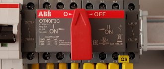
Changeover switch principle of operation
An electrical type device that serves to disconnect an electrical load from one energy source and connect it to another source is called a changeover switch, or a changeover type switch (switch with a midpoint). The devices are available with or without arc arresters. In the first case, network switching can occur with a fully connected load. In the second - only when it is turned off.
The switch is operated manually, that is, if it is necessary to switch power sources, the operator acts on the isolated control lever of the switch. There are also automatic switching systems.
Designation of measuring electrical instruments to characterize circuit parameters
| A heating element |
| UGO | Name |
| PF | Frequency meter |
| PW | Wattmeter |
| PV | Voltmeter |
| PA | Ammeter |
GOST 2.271-74 accepts the following designations in electrical panels for buses and wires:
Letter designations in electrical diagrams
The standards for the letter designation of elements on electrical circuits are described in the GOST 2.710-81 standard with the text title “ESKD. Alphanumeric designations in electrical circuits." The mark for automatic devices and RCDs is not indicated here, which is prescribed in clause 2.2.12 of this standard as a designation with multi-letter codes. The following letter codings are accepted for the main elements of electrical panels:
| Name | Designation |
| Automatic switch in the power circuit | QF |
| Automatic switch in the control circuit | SF |
| Automatic switch with differential protection or difavtomat | QFD |
| Switch or load switch | QS |
| RCD (residual current device) | QSD |
| Contactor | K.M. |
| Thermal relay | F, KK |
| Timing relay | KT |
| Voltage relay | KV |
| Impulse relay | KI |
| Photo relay | KL |
| Surge arrester, arrester | F.V. |
| fuse | F.U. |
| Voltage transformer | TV |
| Current transformer | T.A. |
| A frequency converter | UZ |
| Ammeter | PA |
| Wattmeter | PW |
| Frequency meter | PF |
| Voltmeter | PV |
| Active energy meter | P.I. |
| Reactive energy meter | PK |
| Heating element | E.K. |
| Photocell | B.L. |
| Lighting lamp | EL |
| Light bulb or light indicating device | H.L. |
| Plug or socket connector | XS |
| Switch or circuit breaker in control circuits | S.A. |
| Push-button switch in control circuits | S.B. |
| Terminals | XT |
Representation of electrical equipment on plans
Despite the fact that GOST 2.702-2011 and GOST 2.701-2008 take into account this type of electrical circuit as a “layout diagram” for the design of structures and buildings, one must be guided by the standards of GOST 21.210-2014, which indicate “SPDS.
Images on the plans of conventional graphic wiring and electrical equipment.” The document establishes UGO on plans for laying electrical networks of electrical equipment (lamps, switches, sockets, electrical panels, transformers), cable lines, busbars, tires.
The use of these symbols is used to draw up drawings of electric lighting, power electrical equipment, power supply and other plans. The use of these designations is also used in basic single-line diagrams of electrical panels.
Conventional graphic images of electrical equipment, electrical devices and electrical receivers
The contours of all depicted devices, depending on the information richness and complexity of the configuration, are taken in accordance with GOST 2.302 on the scale of the drawing according to the actual dimensions.
Conventional graphic designations of wiring lines and conductors
Conventional graphic images of tires and busbars
IMPORTANT: The design position of the busbar must exactly coincide on the diagram with the place of its attachment.
Conventional graphic images of boxes, cabinets, panels and consoles
Conventional graphic symbols of switches, switches
On the pages of documentation GOST 21.210-2014 there is no separate designation for push-button switches, dimmers (dimmers). In some schemes, according to clause 4.7. the normative act uses arbitrary designations.
Conventional graphic symbols of plug sockets
Conventional graphic symbols of lamps and spotlights
The updated version of GOST contains images of lamps with fluorescent and LED lamps.
Conventional graphic symbols of monitoring and control devices
How to connect a pass-through switch
A. Zemskov has a whole video about this. Not to say that it is ideal, but on the whole it leaves a feeling of complete understanding of the topic within the framework of the material taught by the author. Yes, of course, there were those who made rude remarks like that such things are called switches because they throw the ends of the chains crosswise. But we and our readers understand that all this is out of envy. Everyone wants to see a good renovation in their home, but not everyone can pay for it as much as Project-Service charges. This is where the misunderstanding comes from. As for A. Zemskov himself, in our humble opinion, the little man who managed to earn such a car legally is worthy of all respect. So, today we are talking about how to connect a pass-through switch.