Everyone understands how you can, using a regular 40-watt EPSN soldering iron and a multimeter, independently repair various electronic equipment with lead-out parts. But such parts are now found, mainly only in power supplies of various equipment, and similar power boards, where significant currents flow and high voltage is present, and all control boards are now based on SMD element base.
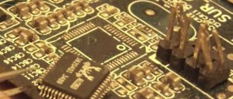
Radio components on the SMD board
So what can we do if we don’t know how to dismantle and solder back SMD radio components, because then we won’t be able to carry out at least 70% of possible equipment repairs ourselves. Someone who is not very familiar with the topic of installation and disassembly may say that this requires a soldering station and a soldering hair dryer, various attachments and tips for them, no-clean flux, such as RMA-223, and the like, which is usually not needed in a home craftsman’s workshop. can not be.
I have at home a soldering station and a hair dryer, nozzles and tips, fluxes, and solder with flux of various diameters. But what if you suddenly need to have your equipment repaired, on the road to order, or while visiting friends? Is it inconvenient to disassemble and bring the defective board home, or to a workshop where the appropriate soldering equipment is available, for one reason or another? It turns out there is a way out, and it’s quite simple. What do we need for this?
What you need for good soldering
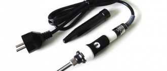
- 1. Soldering iron EPSN 25 watt, with a tip sharpened into a needle, for mounting a new microcircuit.
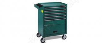
- 2. Soldering iron EPSN 40-65 watts with a tip sharpened to a sharp cone, for dismantling a microcircuit, using Rose or Wood alloy. A soldering iron with a power of 40-65 watts must be turned on via a Dimmer, a device for regulating the power of the soldering iron. You can have one like the one in the photo below, very convenient.
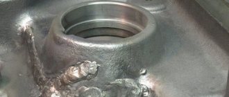
- 3. Rose or Wood alloy. We bite off a piece of solder from the droplet with side cutters, and place it directly on the contacts of the microcircuit on both sides, if we have it, for example, in a Soic-8 package.
- 4. Dismantling braid. It is required to remove solder residues from the contacts on the board, as well as on the chip itself, after dismantling.
- 5. SKF flux (alcohol rosin flux, crushed into powder, dissolved in 97% alcohol, rosin), or RMA-223, or similar fluxes, preferably based on rosin.
- 6. Flux Off flux residue remover, or 646 solvent, and a small brush with medium-hard bristles, which is usually used in school, for painting in art lessons.
- 7. Tubular solder with flux, 0.5 mm in diameter (preferably, but not necessarily this diameter).
- 8. Tweezers, preferably curved, L-shaped.
Wiring of planar parts
So, how does the process itself work? Read something here. We bite off small pieces of Rose or Wood solder (alloy). We apply our flux liberally to all contacts of the microcircuit. We put a drop of solder on Rose, on both sides of the microcircuit, where the contacts are located. We turn on the soldering iron and set it using a dimmer, the power is approximately 30-35 watts, I don’t recommend it anymore, there is a risk of overheating the microcircuit during dismantling. We pass the tip of a heated soldering iron along all the legs of the microcircuit, on both sides.
Dismantling using Rose alloy
In this case, the contacts of the microcircuit will close, but this is not scary, after we dismantle the microcircuit, we can easily remove excess solder from the contacts on the board and from the contacts on the microcircuit using the dismantling braid.
So, we took hold of our microcircuit with tweezers, along the edges, where the legs are missing. Typically, the length of the microcircuit, where we hold it with tweezers, allows us to simultaneously move the soldering iron tip between the tips of the tweezers, alternately on both sides of the microcircuit, where the contacts are located, and slightly pull it up with tweezers. Due to the fact that when melting Rose or Wood alloy, which have a very low melting point (about 100 degrees), relative to lead-free solder, and even ordinary POS-61, and moving with the solder on the contacts, it thereby reduces the overall melting temperature of the solder .
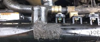
Dismantling microcircuits using braid
And thus the microcircuit is dismantled without dangerous overheating. On the board we have the remains of solder, Rose alloy and lead-free, in the form of sticky contacts. To bring the board back to normal, we take the dismantling braid; if the flux is liquid, you can even dip its tip into it, and place it on the solder “snot” that has formed on the board. Then we heat it from above, pressing it with the tip of a soldering iron, and run the braid along the contacts.
Read also: Do-it-yourself lug lugs for a car
Soldering braided radio components
Thus, all the solder from the contacts is absorbed into the braiding, transferred to it, and the contacts on the board are completely cleared of solder. Then the same procedure must be done with all the contacts of the microcircuit, if we are going to solder the microcircuit into another board, or into the same one, for example, after flashing it using a programmer, if it is a Flash memory chip containing the BIOS firmware of a motherboard, or monitor, or what or other technology. This procedure must be performed to clean the microcircuit contacts from excess solder. After this, we apply the flux again, place the microcircuit on the board, position it so that the contacts on the board strictly correspond to the contacts of the microcircuit, and there is still some space left on the contacts on the board, along the edges of the legs. For what purpose are we leaving this place? So that you can lightly touch the contacts with a soldering iron tip and solder them to the board. Then we take a 25-watt EPSN soldering iron, or a similar low-power one, and touch the two legs of the microcircuit located diagonally.
Soldering SMD radio components with a soldering iron
As a result, the microcircuit turns out to be “stuck” and will not budge, since the melted solder on the contact pads will hold the microcircuit. Then we take solder with a diameter of 0.5 mm, with flux inside, bring it to each contact of the microcircuit, and simultaneously touch the tip of the soldering iron tip, the solder, and each contact of the microcircuit. I do not recommend using solder of a larger diameter; there is a risk of adding “snot”. Thus, we have solder “deposited” on each contact. We repeat this procedure with all contacts, and the microcircuit is soldered into place. If you have experience, all these procedures can actually be completed in 15-20 minutes, or even in less time. All we have to do is wash off the remaining flux from the board with solvent 646, or Flux Off cleaning agent, and the board is ready for tests after drying, and this happens very quickly, since the substances used for rinsing are very volatile. 646 solvent, in particular, is based on acetone. Inscriptions, silk-screen printing on the board, and solder mask are not washed off or dissolved.
The only thing is that dismantling a microcircuit in a Soic-16 or more multi-pin package in this way will be problematic due to difficulties with simultaneous heating and a large number of legs. Happy soldering everyone, and fewer overheated microcircuits! Especially for Radio circuits - AKV .
Why do you need to solder SMD LEDs?
In the manufacture of lighting products that use surface-mount LEDs, SMD LEDs are soldered automatically. Manual soldering of such LEDs may be required in several cases - when repairing devices or when prototyping them during the product design process. Sometimes soldered by hand when starting small-scale production of new products.
In the process of manual and mechanized soldering, the main problem when soldering LEDs onto a board is to maintain the required temperature conditions and not overheat the LED housings. More precisely, semiconductor materials of a light-emitting crystal react poorly to overheating.
The consequence of crystal overheating can be accelerated degradation of the LED, in which:
- The brightness of the LED decreases;
- the shade of light changes;
- An LED can almost go out or physically burn out from overheating in a matter of weeks or even days.
Procedure for manually soldering SMD LEDs onto a board
If you are repairing a lighting product with SMD LEDs, the procedure will consist of the following steps:
- dismantling a failed LED;
- preparing the soldering area for the new LED;
- installing the LED in place and securing it;
- LED soldering;
- Solder washing and protection.
For dismantling, you can use a regular low-power soldering iron, for example, 25 W. The tip is thinned to 1 - 2 mm and the tip is tinned.
If the solders were covered with protective varnish, then either wash it off or carefully tear off a small part with a scalpel or mounting knife. The cleaned area is quickly heated with a soldering iron tip until the solder melts and “wet” it with a piece of shielding braid removed from the cable. For this purpose, you can twist several thin wires into a “tassel”.
This is how all contacts of the LED housing are soldered and cleaned, and then removed from the board. The contact pads on the board are cleaned from solder residues with a soldering iron. The new LED is installed in its regular place. Wet the contact pads and contacts of the SMD housing with alcohol-rosin flux and solder them.
This must be done quickly so that the permissible soldering temperature of the LEDs is not exceeded.
The resulting soldering must have a smooth, shiny surface and completely cover the contact on the case and the contact pad on the board.
After checking the quality of soldering, they are washed with alcohol to remove flux residues. After which they and the LED housings are protected from external influences by applying a layer of protective varnish. This is how they are soldered by hand in small-scale production.
Read also: Types of wear and tear in economics
If it is possible to produce stencils for applying solder paste to the contact pads on the board, then one person can make up to 5 thousand or more thousand solderings per shift. Solder paste is a mixture of flux and dust-like solder.
Nowadays, the most common type of lighting is LED. Thanks to the huge number of advantages, such light sources have taken their place in almost any area of human activity.
Without them it is no longer possible to imagine electronic equipment, modern toys and many other attributes of modern society. LED strips are especially often used as lighting devices today. Therefore, it is very important to know how to solder diodes with your own hands in order to independently repair failed radio-electric parts at home or replace them correctly.
Connection technique using connectors
In the process of repairing such a device, the user may encounter the problem of updating failed crystals. The question of how to solder an LED logically arises if one of the crystals has burned out. This will be indicated by the presence of a black dot on the yellow surface of the element.
And if, under the conditions of a factory layout, the restoration operation is carried out mechanically in an in-line mode, then at home it will be necessary to organize conditions for manual soldering.
What types of LEDs are there?
On the one hand, this approach simplifies the technology of mounting crystals, but on the other hand, it requires more attention from the performer, since one has to deal with elements of miniature sizes, compactly placed in a small space.
Preparation for work
You can give preference to compact models with heating up to 250 °C.
Angle connection technique
The corner joint does not affect the quality of the backlight in any way, but allows you to implement a variety of configurations for splicing LED strips. Problems can only be caused by the presence of a special casing for tapes with a protection class higher than IP68. For example, how to properly solder LEDs filled with silicone or compound? In this case, the initial cleaning procedure becomes more complicated.
We remember the school physics course
In order to solder LEDs (for example, SMD type), you need to know what some of the signs on the circuits mean. Namely:
- "U". This letter on all electrical diagrams indicates voltage. It is measured in V (volts);
- "I". Under this designation lies the current. It is measured in A (amps);
- "R". This letter means the electrical resistance of the circuit elements. This indicator is measured in Ohms (ohms).
All of the above values reflect Ohm's law, which is described by the following formula:
In addition, you need to understand that under the letter “P” is power, which is measured in W (watts). Power is determined by the following formula:
The decoding of these values must be known in order to correctly solder LEDs into any circuits and boards.
Main conclusions
All LEDs, regardless of their operating voltage or current, are connected in series or in parallel. The connection method can also be combined - in this case, the disadvantages of serial and parallel connections are eliminated. It is important to be able to correctly assemble a circuit, select a power source, calculate the values of current-limiting resistors and the required number of LEDs for the circuit to function. A connection without a current-limiting resistor and other protective elements will damage the diode.
How are diodes connected?
Before you start soldering LEDs (for example, SMD type), you need to know how they are connected to the circuit or in series to each other (if we are talking about LED strips).
Note! LEDs are most often connected to a network with a voltage of 12 or 9 V. But usually the devices are designed for a current consumption level of 0.02 A (20 mA).
The ideal option for LEDs is to connect them through a current stabilizer. It should be remembered that such stabilizers will cost slightly more than single LEDs (for example, SMD type). This must be taken into account when independently assembling radioelectric devices.
In order to power yellow and red LEDs, a voltage of 2.0 V is often required. At the same time, to power blue, green and white LEDs - 3.0 V. The following example will help to understand this issue:
- a 12 V battery is available, as well as 0.02 A and 2.0 V LEDs;
- the simplest solution here would be to supply a voltage of 2.0 V to each diode;
- in this case, the extra 10 V will need to be extinguished using a resistor. It is also often called resistance;
- Using Ohm's law, we calculate the resistance value (R = U/I). As a result, we get R = 10.0/0.02 = 500 Ohm;
- Also, in order to protect the resistance from excess heat, it is necessary to calculate its power. The result will be P = 10.0 * 0.02 A = 0.2 W.
For greater reliability, it is necessary to take a resistance of slightly larger capacity. Note! As the resistance power increases, its overall dimensions will naturally increase. Knowing the above aspects, you will be able to connect the LEDs to the battery correctly using a resistor for this. The main thing here is to strictly observe the polarity of the parts used.
What is needed for work
Many radio electronics enthusiasts who practice self-assembly of various devices are interested in the possibility of independently soldering LEDs (for example, SMD type) for circuits. If you have the proper tools and knowledge, creating such circuits yourself is quite possible. For this type of work you will need:
- tester;
- calculator;
- medical tweezers (optional, but recommended);
- soldering iron
Note! When working with LEDs, especially when testing them, you need to be careful not to direct the beam coming from these elements into your eyes.
As you can see, the set of tools here is small and can easily be found in any home. With this kit, you will be able to correctly solder diodes, both in the circuit and in series as part of the LED strip.
Heating from below
This technique is not only useful when working with a soldering gun, but also increases the convenience of soldering.
The board is secured with a clamp, the temperature is set to 200 degrees and warmed up for five minutes, after which they begin to work as usual.
Using thermal tape, you can shield nearby elements.
After removing the chip, the contacts are cleaned with the above braid. Do the same with the board.
All procedures must be carried out carefully to prevent damage to the circuit. If you don't have copper braid on hand, you can remove the solder using a soldering iron with a thin tip.
The structure of diode elements and how to solder them
A standard LED is a glass bulb with an approximate diameter of 5 mm, to which lead legs are attached.
Diode appearance
The short leg represents the negative terminal, and the long leg represents the positive terminal. If you mix them up when soldering, the LED will not light up. The process of soldering such elements has the following algorithm:
- We place each diode in its own place;
- soldering areas should be treated with ordinary tin or flux;
- after that, apply a soldering iron to them for a couple of seconds;
- After this, the remaining legs can simply be bitten off.
After you have soldered all the LEDs to the circuit, you need to check your handiwork. To do this, they must be connected to power. If all the diodes light up, this means that you did everything correctly. In addition, there are LEDs, which, for ease of working with them, are produced in the form of special strips. They can be cut and connected to each other, which makes it possible to use them for lighting rooms, shop windows, etc.
Read also: How to hang a TV on a wall bracket
Places for cutting LED strips and soldering wires
Such tape should only be cut in appropriate places. If you cut in another place, you will simply ruin the product by damaging the LED connection. Such pieces need to be soldered using special contact pads that end these sections.
Note! You can solder LED strips using a soldering iron with a power of 40 V.
As a flux, you should use a special solution that looks like a gel. Remember that the ends of the wires in this situation should be well tinned. You can also use special devices to create contacts between pieces of LED strip - connectors. But they are quite expensive, so they are rarely used.
How the design of a 220 V LED lamp affects its repair: 3 important features
Here it is important to clearly understand the processes that accompany the conversion of electrical energy into luminous flux, which are incorporated into the design of the lamp.
2 technologies for creating luminous flux with a light source: 2 approaches to repairing LED lamps
All 220 V ice lamps can be divided into 2 classes, using:
- conventional solid-state crystals on DIP, SMD or COB LEDs;
- light-emitting filament-like elements of the “Filament” type, made from a large number of serial chains of LED crystals.
- made for a single standardized base type, usually E 27 or E14;
- have the same type of system for connecting semiconductor junctions to a 220 volt network through a simplified power supply or driver.
However, the filament lamp has a more complex structure:
- her chains of LED crystals are assembled into a single thread, closed in a glass bulb with a phosphor coating that corrects the quality of LED lighting;
- filament threads are so oriented in space that light from the source is emitted evenly in all directions, like an Ilyich light bulb;
- the entire lighting structure is placed in a hermetically sealed glass case and filled with helium, which improves heat removal from semiconductor elements;
- The power of one thread is selected so that it is 1 watt. This allows you to visually assess the consumption of a filament source by their quantity.
Repairing a Filament lamp involves opening the housing and breaking its seal. This worsens the design intent, affects the interior, and slightly changes heat transfer, which has a slight effect on the service life of the repaired lamp.
There is another technical rationale for this issue.
Alternative opinion: the Filament lamp, switched on without a bulb, ensures that the LEDs operate with an open internal space, ensuring their cooling due to natural air circulation.
This technique can be used for light sources located in dry rooms inaccessible to accidental human touch. However, you can make the choice yourself.
When one crystal of a filament strand is damaged, the entire chain fails. It needs to be completely replaced. There are no other repair options, and there are no spare parts for sale. Therefore, such defective light bulbs are first accumulated, and then one good one is collected from several damaged ones.
You have to put up with the above feature of repairing ice lamps with filament threads. The home handyman does not have the technical ability to get around this problem.
Conventional SMD LED light bulbs allow disassembly of the housing and subsequent repair of any elements with full restoration of the optical and electrical characteristics of the manufacturer without loss of quality.
Expert opinion
It-Technology, Electrical power and electronics specialist
Ask questions to the “Specialist for modernization of energy generation systems”
Work order To accurately place the part in the seat, you must first solder one of its outer legs, after which the component can be easily aligned. Ask, I'm in touch!
Soldering Features
After we have refreshed our school knowledge and the basics of connecting LED elements, and also found all the necessary tools, we can begin to directly work with the parts. LEDs can be connected in series. The important thing here is to know how to do it correctly.
Note! In order to solder diodes in series, they should be selected with the same parameters.
The resulting chains of LEDs can be used in a wide variety of devices and purposes. Most often, they are used to organize various types of lighting (open or closed) for premises, as well as vehicles. When installing such chains, you should remember that the voltage in the car's electrical network will be higher than 12 V (14-14.5 V). The machine's power supply is not characterized by constant voltage. To suppress possible interference, special voltage stabilizers are needed.
Independent assembly of voltage stabilizers is possible on the basis of KREN8A and K142EN8A microcircuits for a 9 V network. KREN8B and K142EN8B microcircuits are suitable for a 12 V network. A small-sized soldering iron is suitable for soldering this element. Its tip should heat up to 260 degrees.
Note! The duration of the soldering process for each point should be 3-5 seconds.
To ensure that the soldering itself went correctly, you need to know the following rules and recommendations:
- If you don’t have even minimal soldering experience, you need to practice first. Otherwise, there is a high risk that the LEDs will not work or will even deteriorate. To improve your skills, you should use wires with different cross-sections;
- It is imperative to use standard tin-lead solder and flux for aluminum;
Flux for aluminum
- Wires that have not been covered with oxides must be tinned immediately after exposure. To do this, you need to take a small amount of solder and heat it on the soldering iron tip. Then we touch the rosin with it and run it along the exposed sections of the wires. As a result of such manipulations, the solder will spread into a thin film;
- sometimes tinning is not allowed. Then the wire should be placed on an aspirin tablet and heated with a soldering iron. Heating lasts 3-5 seconds.
LED soldering process
Knowing these rules, you can correctly solder the LEDs in series.
Hi would you mind letting me know which web host you're using? I've loaded your blog in 3 completely different browsers and I must say this blog loads a lot quicker then most. Can you recommend a good hosting provider at a fair price? Many thanks, I appreciate it!
Review from admin - 05/27/2012 at 17:49
Hi to all, how is all, I think every one is getting more from this website, and your views are nice for new users..
Review from admin - 07/17/2012 at 18:43
I think other site proprietors should take this site as an model, very clean and wonderful user friendly style and design, let alone the content. You are an expert in this topic!
Review from admin - 07/17/2012 at 17:47
I simply want to say I'm very new to blogging and certainly enjoyed this web page. Likely I'm planning to bookmark your blog. You absolutely come with incredible articles. Thanks a bunch for sharing your website page.
Review from admin - 07/17/2012 at 17:14
Unfortunately, your search returned no results.
Source
Another soldering option
In addition to conventional LEDs, there are chips that are mounted in LED strips. The most common LEDs today are SMD type.
This circuit element is a leadless component. SMD does not have traditional copper lead wires. Therefore, such elements are connected using printed circuit board tracks. Soldering is also used to connect the SMD diode to the board. It is necessary to solder track tracks and contact pads to them. Soldering such a circuit component is not difficult, since for this you can use a low-power type of soldering iron with a capacity of 10-12 W. Therefore, you can quite conveniently and quickly solder each contact in series separately.
There are situations when it is necessary to desolder SMD components to replace or test them. In such a situation, in order to prevent the element from overheating, you need to warm up all its terminals at the same time. If such a need with SMD components happens often, then it makes sense to purchase a special set of soldering iron tips. These stings should have two or three small branched ends. They are very easy to work with SMD as the risk of damage is minimized even when they are glued to the PCB. Sometimes it is impossible to use a low-power soldering iron. Then, in order not to damage the element during soldering, a copper wire with a diameter of one millimeter should be wound to the tip of a powerful soldering iron.
Wire wound around tip
Such a homemade attachment will be quite easy to use with a powerful soldering iron when working with SMD LEDs.
Dismantling techniques
So, first we will talk about the most popular technology - how to desolder a part from a board with a soldering iron without additional equipment.
After which we will briefly consider simpler methods. If you want to remove an electrolytic capacitor, just grab it with tweezers (or an alligator clip), heat the 2 terminals and quickly but carefully remove them from the board.
The situation is exactly the same with transistors. Apply solder to all 3 pins and remove the radio component from the board.
As for resistors, diodes and non-polar capacitors, very often their legs are bent during soldering from the back side of the board, which makes it difficult to solder without additional devices. In this case, it is recommended to first heat one terminal and, using a crocodile clip, with a little effort, pull part of the part out of the circuit (the leg should straighten). Then we perform a similar procedure with the second output.
We examined this technique when there is nothing at hand except a soldering iron. But if you purchased a set of needles, then it will be even easier to desolder the element: first, heat up the contact with a soldering iron, then place a needle of a suitable diameter on the pin (it should go through the hole in the microcircuit) and wait until the solder cools down. After this, we take out the needle and get a bare lead, which can be easily removed. If the radio component has several legs, we proceed in the same way - warm up the contact, put on the needles, wait and remove.
You can clearly see everything that we talked about in this article in the video, which provides the technology for desoldering elements from the board:
By the way, instead of special needles, you can even use ordinary ones that come with a syringe. However, in this case, you initially need to sharpen the end of the needle so that it is at a right angle.
Desoldering the part using a desoldering braid is also not difficult. Before starting work, wet the end of the winding with alcohol-rosin flux. After this, apply the braid at the desoldering site (on the solder) and heat it with a soldering iron tip. As a result, the heated solder should be absorbed into the braiding, which will free the terminals of the radio components.
With a desoldering pump, things are similar - the spring is charged, the contact is heated, after which the tip is brought to the molten solder and the button is pressed. A vacuum is created, which draws the solder into the desoldering pump.
That's all I wanted to tell you about how to desolder radio components from a board at home. We hope that the provided techniques and video lessons were useful and interesting for you. Finally, I would like to note that you can desolder the elements from the microcircuit with a hair dryer, but we do not recommend doing this. A hair dryer can damage nearby parts, as well as the parts you want to remove!
Interesting
Many people wonder how to properly solder SMD components. But before we deal with this problem, it is necessary to clarify what these elements are. Surface Mounted Devices - translated from English, this expression means surface-mounted components. Their main advantage is their greater mounting density than conventional parts. This aspect affects the use of SMD elements in the mass production of printed circuit boards, as well as their cost-effectiveness and manufacturability of installation. Conventional parts with wire-type leads have lost their widespread use along with the rapidly growing popularity of SMD components.