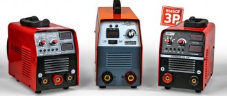
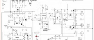
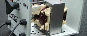
The circuit of a welding inverter is fundamentally different from the design of its predecessor, the welding transformer. The basis of the design of previous welding machines was a step-down transformer, which made them large and heavy. Modern welding inverters, thanks to the use of advanced developments in their production, are lightweight and compact devices characterized by wide functionality.
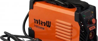
Welding inverter without cover
The main element of the electrical circuit of any welding inverter is a pulse converter that generates high-frequency current. It is thanks to this that the use of an inverter makes it possible to easily ignite the welding arc and maintain it in a stable state throughout the welding process. The welding inverter circuit, depending on the model, may have certain features, but the principle of its operation, which will be discussed below, remains unchanged.
What types of inverters are available on the modern market?
For a certain type of welding, you should choose the right inverter equipment, each type of which has a specific electrical circuit and, accordingly, special technical characteristics and functionality.
Inverters produced by modern manufacturers can be used equally successfully both in industrial enterprises and in everyday life. Developers are constantly improving the electrical circuit diagrams of inverter devices, which allows them to be equipped with new functions and improve their technical characteristics.
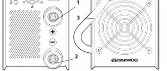
The number of connectors and controls on the front panel speaks volumes about the capabilities of the welding inverter
Inverter devices as the main equipment are widely used to perform the following technological operations:
- electric arc welding with consumable and non-consumable electrodes;
- welding using semi-automatic and automatic technologies;
- plasma cutting, etc.
In addition, inverter machines are the most efficient type of equipment used for welding aluminum, stainless steel and other difficult-to-weld metals. Welding inverters, regardless of the features of their electrical circuit, allow you to obtain high-quality, reliable and neat welds made using any technology. At the same time, what is important is that the compact and not too heavy inverter machine, if necessary, can be easily moved at any time to the place where welding work will be performed.
Mobility is one of the advantages of inverter devices
Philosophy for choosing a solar power system
Just as with choosing a stabilizer, you need to honestly ask yourself the question - “Why install solar panels and batteries with an inverter?” The completeness of the system and the price will greatly depend on the correct answer. In terms of price, you can save tens of thousands of rubles, and everything will work perfectly.
So, you need to decide what the system will be used for.
Emergency reserve
In the event of a short-term power failure in the city network, it is necessary to ensure the operation of vital appliances in the house - heating, communications, lighting, refrigerator. If possible, do not use all other devices. It is assumed that the accident is a rare and short-lived event.
In this case, the system configuration with solar inverter and batteries will be minimal.
2. Savings
If you plan to use solar energy to save money, then you need to increase the power of the system. And choose a mode of operation of the inverter when the energy of the sun is “mixed” with the energy that we pay on the meter. Or some lines are constantly powered only by solar panels.
This saves the electricity we receive from the city, while keeping the consumption of the entire house constant. And in this case, we can talk about the payback of such a solar-powered system.
Of course, this option also includes emergency power supply, i.e. first case.
Complete replacement
This option is a complete rejection of the city power grid. The city power grid will only be needed for emergency backup of the solar-powered system if it suddenly fails. This system configuration will have maximum power and cost.
In this case, it is also advisable to have a generator, which will be needed in case of insufficient energy from the sun. This can happen, for example, in winter, when solar activity is minimal. The generator will serve to charge the batteries and power the important load.
What does the design of a welding inverter include?
The welding inverter circuit, which determines its technical characteristics and functionality, includes such mandatory elements as:
- a unit that provides electrical power to the power part of the device (it consists of a rectifier, a capacitive filter and a nonlinear charging circuit);
- power part, made on the basis of a single-cycle converter (this part of the electrical circuit also includes a power transformer, a secondary rectifier and an output choke);
- power supply unit for elements of the low-current part of the electrical circuit of the inverter apparatus;
- PWM controller, which includes a current transformer and a load current sensor;
- a block responsible for thermal protection and control of cooling fans (this block of the circuit diagram includes inverter fans and temperature sensors);
- controls and indications.
How does a welding inverter work?
The formation of a high current, with the help of which an electric arc is created to melt the edges of the parts being joined and the filler material, is what any welding machine is designed for. For the same purposes, an inverter apparatus is also needed, which allows the generation of welding current with a wide range of characteristics.
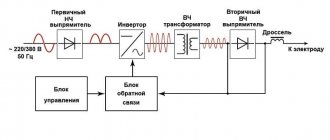
In its simplest form, the principle of operation of the inverter looks like this.
- Alternating current with a frequency of 50 Hz from a regular electrical network is supplied to the rectifier, where it is converted into direct current.
- After the rectifier, the direct current is smoothed using a special filter.
- From the filter, direct current flows directly to the inverter, whose task is to convert it again into alternating current, but at a higher frequency.
- After this, using a transformer, the voltage of the alternating high-frequency current is reduced, which makes it possible to increase its strength.
Block diagram of an inverter type welding machine
In order to understand the importance of each element of the electrical circuit diagram of an inverter device, it is worth considering its operation in more detail.
Industrial products
Industrial designs of generators used to supply power to mobile welded equipment can have a wide variety of designs. From the point of view of economy and efficiency, the option of a gasoline unit of the same inverter type is considered optimal. In this case, preference is usually given to devices from the same manufacturers, designed specifically for working with inverter welding equipment (figure below in the text).
It is believed that it is this combination of these two components of the working complex that makes it possible to obtain a sufficiently stable arc and provide the required parameters of high-frequency voltage and pulse current. According to their class and intended purpose, all existing welding devices are divided into the following types:
- Purely industrial designs;
- Professional models;
- Inexpensive household products.
Industrial and professional models are mainly used for the manufacture of volumetric metal structures and are designed for round-the-clock operation for long periods of time. For their normal functioning, significant operating currents will be required, capable of ensuring high-quality assembly of industrial structures. This type of welding device will require gasoline generators capable of delivering currents of up to 250-500 Amperes (see photo below).
Summarizing the consideration of possible options for choosing a generating device for an inverter, it is necessary to note the following. When thinking about the question of which generator is best to choose for welding, most users give preference to small-sized gasoline units in inverter design.
Processes occurring in the electrical circuit of a welding inverter
The circuit of an inverter-type welding machine allows you to increase the current frequency from the standard 50 Hz to 60–80 kHz. Due to the fact that high-frequency current is subject to regulation at the output of such a device, compact transformers can be effectively used for this. An increase in the frequency of the current occurs in that part of the inverter electrical circuit where the circuit with powerful power transistors is located. As you know, only direct current is supplied to transistors, which is why a rectifier is needed at the input of the device.
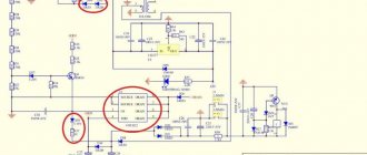
Schematic diagram of the factory welding inverter "Resanta" (click to enlarge)
Inverter circuit from the German manufacturer FUBAG with a number of additional functions (click to enlarge)
An example of a circuit diagram of a welding inverter for self-production (click to enlarge)
The electrical circuit diagram of the inverter device consists of two main parts: the power section and the control circuit. The first element of the power section of the circuit is a diode bridge. The task of such a bridge is precisely to convert alternating current into direct current.
In the direct current converted from alternating current in the diode bridge, pulses may occur that need to be smoothed out. To do this, a filter consisting of capacitors of predominantly electrolytic type is installed after the diode bridge. It is important to know that the voltage that comes out of the diode bridge is approximately 1.4 times greater than its value at the input. When converting AC to DC, rectifier diodes become very hot, which can seriously affect their performance.
Components of a welding inverter using the example of a homemade machine
To protect them, as well as other elements of the rectifier from overheating, radiators are used in this part of the electrical circuit. In addition, a thermal fuse is installed on the diode bridge itself, the task of which is to turn off the power supply if the diode bridge has heated up to a temperature exceeding 80–90 degrees.
High-frequency interference generated during operation of the inverter device can enter the electrical network through its input. To prevent this from happening, an electromagnetic compatibility filter is installed in front of the rectifier block of the circuit. Such a filter consists of a choke and several capacitors.
Inverter power supply
The inverter itself, which converts direct current into alternating current, but with a much higher frequency, is assembled from transistors using an “oblique bridge” circuit. The switching frequency of transistors, due to which the alternating current is generated, can be tens or hundreds of kilohertz. The high-frequency alternating current thus obtained has a rectangular amplitude.
A voltage-reducing transformer installed behind the inverter unit allows you to obtain a current of sufficient strength at the output of the device so that you can effectively perform welding work with its help. In order to obtain direct current using an inverter apparatus, a powerful rectifier, also assembled on a diode bridge, is connected after the step-down transformer.
Transistors for the power module of the welding inverter
Best Cheap Generators
To make it easier for you to choose a generator for your welding machine, we will additionally tell you about four high-quality models for your home and garage. This is not a rating, but rather a list of excellent generators that have performed well in a variety of conditions.
Huter DY6500L
The Huter DY6500L generator is an excellent helper in the household. Its power is 5 kW, which is enough to power a low-power inverter delivering up to 150 Amps. This is a synchronous generator running on gasoline fuel. For full operation, it is recommended to use gasoline of a grade not lower than AI-92. This model can also run on propane. Tank with a capacity of 22 liters.
Huter DY6500L is started using a recoil starter. There is a built-in forced cooling system, it is of the air type. The weight of the generator is about 80 kg, which is quite a lot. But two or three people can move it to the right place without any problems.
BRIMA LT 8000 B
We also recommend the LT 8000 B model from the famous German brand BRIMA for inverter welding. Its power is slightly more than that of the previous generator - 6 kW. But this is its rated power. And the maximum is 6.5 kW. However, remember that we do not recommend constantly using the generator beyond its capabilities. The LT 8000 B model is useful for those whose machine produces up to 180 Amps of welding current.
This is also a gasoline generator. Tank capacity - 25 liters. Powered by a reliable 190F engine. It is four-stroke, equipped with forced air cooling. Starting is carried out using built-in electronics. The generator can work without a break for up to 8 hours, then it needs a break to avoid overheating.
Inverter protection and control elements
Several elements in its circuit diagram allow you to avoid the influence of negative factors on the operation of the inverter.
To ensure that transistors that convert direct current into alternating current do not burn out during their operation, special damping (RC) circuits are used. All electrical circuit blocks that operate under heavy load and become very hot are not only provided with forced cooling, but are also connected to temperature sensors that turn off their power if their heating temperature exceeds a critical value.
Radiators and cooling fans take up significant space inside the inverter
Due to the fact that the filter capacitors, after being charged, can produce a high current, which can burn the inverter transistors, the device must be provided with a smooth start. For this purpose, stabilizers are used.
The circuit of any inverter has a PWM controller, which is responsible for controlling all elements of its electrical circuit. From the PWM controller, electrical signals are sent to a field-effect transistor, and from it to an isolation transformer, which simultaneously has two output windings. The PWM controller, through other elements of the electrical circuit, also supplies control signals to the power diodes and power transistors of the inverter unit. In order for the controller to effectively control all elements of the inverter's electrical circuit, it is also necessary to supply electrical signals to it.
To generate such signals, an operational amplifier is used, the input of which is supplied with the output current generated in the inverter. If the values of the latter diverge from the specified parameters, the operational amplifier generates a control signal to the controller. In addition, the operational amplifier receives signals from all protective circuits. This is necessary so that he can disconnect the inverter from the power supply at the moment when a critical situation arises in its electrical circuit.
Selecting the power of a solar system
Before purchasing and installing a solar inverter, you should take the time to analyze your home's existing electrical system. Determine the maximum and average power consumption, starting currents, and grounding system.
I recommend your article about all existing grounding systems, their differences, advantages and disadvantages.
The inverter power must be selected equal to or greater than the maximum consumption of the house.
It is logical that the power and efficiency of the entire system depends on the batteries. To inverters of different capacities you need to connect batteries of different capacities and connect them in series:
Diagram of connecting batteries to inverters of various capacities
It is possible to connect inverters in parallel to obtain more power. To do this, you need to additionally use communication boards (parallel operation) so that the inverters can work correctly. Here is an example of a connection diagram when the powers of two inverters are added:
Two inverters in parallel. Connection diagram for inverters for solar panels
The power of the inverter will determine the power of the entire system. But not everything is so simple here, and it is worth considering some factors.
Real inverter power
The entire load is never switched on at once and a careful analysis of consumption needs to be done over time. To do this, you can use a current clamp or a voltage quality analyzer. I wrote about examples of using the HIOKI 3197 voltage quality analyzer here and here.
Bypass
In Bypass mode, the inverter passes all the power of the home network through itself. And you need to take into account that the power during bypass (when the inverter is not actually working) and during conversion is the same. At least that's what the manufacturer claims.
Overload
Some household electrical appliances only work for a short time. For example, a kettle or microwave oven is usually turned on for 2-3 minutes. Other devices with electric motors have inrush currents that last several seconds.
These factors are usually taken into account in inverters, and they can handle an overload of 2-3 times for several seconds, and an overload of 1.5 times for several minutes. These values, of course, are approximate and depend on the inverter model.
Priorities
It is necessary to decide which devices need uninterrupted power supply and which can “suffer”. Therefore, it would be wise to connect not all electrical appliances through a solar inverter, but only the most important ones. For example, an electric boiler, kitchen sockets (including a refrigerator), lighting.
And connect very powerful and not so necessary devices directly, bypassing the inverter. This could be a boiler, instantaneous water heater, etc.
Taking into account all these factors will help you choose the right inverter for your home and save wisely.
Advantages and disadvantages of inverter-type welding machines
Inverter welding machines, which replaced the usual transformers, have a number of significant advantages.
- Thanks to a completely different approach to the formation and regulation of welding current, the weight of such devices is only 5–12 kg, while welding transformers weigh 18–35 kg.
- Inverters have very high efficiency (about 90%). This is explained by the fact that they spend significantly less excess energy on heating the components. Welding transformers, unlike inverter devices, get very hot.
- Due to such high efficiency, inverters consume 2 times less electrical energy than conventional transformers for welding.
- The high versatility of inverter machines is explained by the ability to regulate the welding current over a wide range with their help. Thanks to this, the same device can be used for welding parts made of different metals, as well as for welding using different technologies.
- Most modern inverter models are equipped with options that minimize the impact of welder errors on the technological process. Such options, in particular, include “Anti-stick” and “Arc Force” (fast ignition).
- Exceptional stability of the voltage supplied to the welding arc is ensured by the automatic elements of the inverter electrical circuit. In this case, automation not only takes into account and smoothes out differences in input voltage, but also corrects even such interference as the attenuation of the welding arc due to strong wind.
- Welding using inverter equipment can be performed with any type of electrode.
- Some models of modern welding inverters have a programming function, which allows you to accurately and quickly configure their modes when performing a certain type of work.
Like any complex technical devices, welding inverters have a number of disadvantages that you also need to be aware of.
- Inverters are highly expensive, 20–50% higher than the cost of conventional welding transformers.
- The most vulnerable and often failing elements of inverter devices are transistors, the cost of which can be up to 60% of the price of the entire device. Accordingly, repairing a welding inverter is quite an expensive undertaking.
- Due to the complexity of their electrical circuitry, inverters are not recommended for use in bad weather conditions and at low temperatures, which seriously limits their scope of application. In order to use such a device in field conditions, it is necessary to prepare a special closed and heated area.
When welding work performed using an inverter, long wires cannot be used, as they induce interference that negatively affects the operation of the device. For this reason, the wires for inverters are made quite short (about 2 meters), which makes welding work somewhat inconvenient.
Other DIY connection methods
In an older home, the protective devices, wiring, and outlets are not designed to withstand heavy loads. High current causes a short circuit. Voltage surges can damage household appliances in your own apartment and those of your neighbors. To eliminate connection problems, you should consider solving this and other typical problems.
Using a current generator
To organize autonomous power supply, a compact power plant with a gasoline (diesel) engine is used. Such a generator can be purchased or rented for the duration of work operations. When choosing equipment, check:
- power;
- voltage stabilization;
- compliance with working conditions.
Calculation of output parameters for the considered example with welding of thick sheets:
- current – 240 A;
- voltage – 40 V;
- power – 9600 W = 240*40.
A 10 kW generator in this mode will operate at the limit of its capabilities. This reduces the life of functional units and increases the risk of overheating and breakdowns. To eliminate negative factors, choose a source with a power reserve of 25±5%.
Using extension cords
The length of the serial network cable does not exceed 4 m. To expand the working area, a “carrying” is used. If the welding current is not more than 150 A, a 20-meter extension cord with a conductor cross-sectional area of 2.5 mm square is suitable. The power line is installed without bends to eliminate the parasitic influence of inductive reactance.
We recommend reading: How to repair a welding inverter yourself
Selecting cable parameters
To transmit high current, a conductor with a large cross-section in a thick protective sheath is used. Fixed terminals are used to connect to the welding machine. When choosing a cable, pay attention to the following details:
- copper conductor provides low resistivity;
- the use of aluminum reduces the cost of the product;
- the multi-core design maintains the integrity of the core after repeated twisting/straightening cycles;
- The shell with special additives is resistant to high and low temperatures.
Important parameters of cable products are determined by special markings in the name:
- HL (T) – the product is intended for use in cold climates down to -60°C (tropical);
- N – non-combustible insulation;
- KG – flexible cable;
- PES is a modification for a semi-automatic device.
A suitable cross section is selected taking into account the current strength (maximum):
- 6 mm sq. – 100 A;
- 10 – 120;
- 25 – 200;
- 35 – 290;
- 50 – 300.
| Conductor cross-sectional area, mm sq. | |||
| Current (I), A | Cable length, m | ||
| 0-15 | 15-30 | 30-60 | |
| 30-100 | 25 | 25 | 50 |
| 100-200 | 35 | 50 | 70 |
| 200-300 | 50 | 70 | 90 |
For an accurate calculation, use the formula D=S/K, where:
- D – permissible length;
- C – cross-sectional area;
- K – correction factor (K=I/100).
When checking the package, in addition to the cable, you should select the correct holder and clamp for connecting the ground.
When choosing a cable, you need to pay attention to a number of details.
