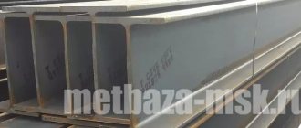
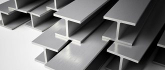
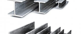
I-beam is one of the most popular types of rolled metal products. It is characterized by increased strength, so, if you compare it with a standard rectangular profile, it will be 7 times stronger and almost 30 times stiffer, and the H-shaped section allows I-beams to be a means of transferring high vertical and horizontal loads to the main load-bearing support .
Due to these properties, I-beams are widely used in construction and mechanical engineering as an element of suspended tracks, support and column structures, load-bearing strength ribs as part of heavy mechanisms, etc. As a rule, carbon and low-alloy steels are used in the production of I-beams. They are made by hot rolling or rolling in metallurgical mills.
TECHNICAL REQUIREMENTS
2.1. Design documentation.
2.1.1. The design documentation used must be reviewed and accepted for work in the prescribed manner.
2.1.2. All changes to the project (drawings) during the period of work must be agreed upon with the organization that developed the project.
2.1.3. The drawings must indicate:
- all dimensions necessary for manufacturing;
— test conditions and parameters;
— type and scope of inspection of welded joints;
— specification of sheets and parts, indicating quantity and weight, steel grade;
2.2. Materials.
2.2.1 Welded steel I-beams are made from hot-rolled steel,
supplied in sheets in accordance with GOST 19903, made of steel:
- carbon general purpose and low-alloy with a thickness of 6 mm or more - according to GOST 27772;
— carbon general purpose with a thickness of 6 mm or more - according to GOST 14637;
- low-alloy thickness 6 mm or more - according to GOST 19281.
The brand, quality category, and strength class of steel are indicated in the order.
2.2.2. The quality of materials must be confirmed by manufacturer certificates.
2.2.3. In the absence of a certificate or incompleteness of the certificate data, the use of the material may be possible only after testing and compliance of all properties with the requirements of the regulatory document.
2.2.4. Each piece supplied sheet or package of sheets must be marked or labeled with a clear indication of the following data:
— manufacturer;
- trademark;
— number of the standard or technical specifications;
— sheet size;
— grade of material and heat number;
- weight of the package.
2.2.5. Welding materials (welding wire, electrodes, flux, carbon dioxide
and/or gas mixtures) must be used in accordance with SNiP II-23 and ensure the tensile strength of the welded joint metal is not lower than that of the base metal.
2.2.6. Spots, cracks, flaws, and sunsets are not allowed on the surface of the sheet.
The range of welded beams produced by ChZSB LLC is an analogue of the section according to STO ASChM 20-93
Application
The use of metal beams is very diverse. Their most important purpose is related to the construction industries. In addition, such metal products are used in:
- mechanical engineering;
- automotive industry;
- carriage building;
- metallurgical industry;
- agriculture and national economy;
- mining and extractive industries.
These steel profiles are used to install floors for industrial and civil construction projects, massive columns, bridge supports, overhead tracks, and more. Special profiles are widely used in the construction and reconstruction of hydroelectric power stations, metro stations, and for reinforcing shafts in mines.
The full texts of GOSTs in PDF format can be downloaded from the links below. GOST 8239-89 Hot-rolled steel I-beams, GOST 19281-89 Rolled high-strength steel, GOST 19425-74 I-beams and special steel channels.
PRODUCTION OF WELDED BEAM
3.1. The cross section of the beam must correspond to Figure 1.
H – beam height; h – height of the beam wall; s – wall thickness;
t – flange thickness; B – shelf width
Figure No. 1
3.2. The dimensions of the beams, the cross-sectional area, the mass of one meter of the beam and the geometric values for the axes are given in Table 1.
Table No. 3
| I-beam dimensions, mm | Mill NNKh 1500 |
| Length, L | 6 000-15 000 |
| Wall height, h | 200 — 1500 |
| Shelf width, when symmetrical location relative to the wall, B | 200 — 600 |
| Wall thickness, S | 6 — 30 |
| Shelf thickness, t | 8-40 |
The main technical parameters of the mill are shown in Table 3 and Figure 1.
3.3. In accordance with the order, a welded beam with a length from 3000 mm to 12000 mm . At the customer's request, it is possible to supply beams up to 15,000 mm. With full penetration, beams are manufactured with a wall thickness of up to 12 mm.
3.4. The maximum deviations in wall thickness during the manufacture of a welded beam and beam flange must correspond to the maximum deviations in the thickness of the original workpiece with a width of over 1500 to 2000 mm.
3.5. Deviation from the perpendicularity of the ends of the beam should not take its length beyond the maximum deviations. The maximum length of a conventionally assembled welded beam with ends perpendicular to the longitudinal axis is taken as the length of the beam.
3.6. Maximum deviations of dimensions, geometric shape of a welded beam and welded
seams should not exceed the values given in table 2, the minimum size of the seam leg is determined by the ChZSB assortment:
K = at least 4 mm for beams: 25B1, 25B2, 30B1, 30B2, 35B1;
K = at least 5 mm for beams: 35B2, 40B1, 40B2, 45B1, 45B2, 50B1, 50B2, 55B1, 25Ш1, 30Ш1, 35Ш1, 35Ш2, 40Ш1, 25К1, 25К2, 30К1;
K = at least 6 mm for beams: 50B3, 55B2, 60B1, 60B2, 70BS, 70B1, 70B2, 30Sh2, 40Sh2, 45Sh1, 50Sh1, 50Sh2, 50Sh3, 60Sh1, 60Sh2, 70Sh1, 80Sh1, 90Sh1, 25K3 , 30K2, 30K3 , 30K4, 35K1, 35K2, 40K1;
K = at least 7 mm for beams: 50Ш4, 60Ш3, 60Ш4, 70Ш2, 70Ш3, 80Ш2, 90Ш2, 100Ш1, 100Ш2, 100Ш3, 40К2, 40К3, 40К4;
K = at least 8 mm for beams: 70Ш4, 70Ш5, 100Ш4, 40К5.
3.7. At the customer's request, end cutting is carried out. The maximum deviations of the cut oblique must correspond to the value specified in Table 2.
3.8. Types of tests and scope of inspection of welded joints are selected depending on the established quality level in accordance with GOST 23118 - 99.
Dimensions
I-beams GOST 8239 are produced in sizes from 10 to 100. The size determines the height in centimeters. The 10th I-beam has a height of 10 cm, a shelf - 55 mm, a shelf thickness of 4.5 mm. Moreover, the weight of one meter of such a structure will be 9.460 kg. One 6-meter rod of such a metal product will weigh 57 kg. 1 ton of rolled metal contains just over 17 meters of 10-size beams. These indicators are available in special reference tables. The standard steel profile sizes are 10, 18, 20, 30. In huge structures of large-scale construction, bridge construction, construction of dams, power plants, powerful profiles of 80 or 100 sizes are used. On special requests, it is possible to produce I-profiles of larger sizes and specific requirements. I-beam, the price for such metal products made to order is determined by agreement.
ASSEMBLY AND WELDING WORKS
4.1. The welding materials, equipment and technologies used must be certified in accordance with the requirements of RD 03-613-03, RD 03-614-03, RD 03-615-03.
4.2. The edges of the beam flanges after machine oxygen cutting should not have irregularities exceeding 0.3 mm.
4.3. T-belt (belt) and butt (joints of sheets of shelves and walls) seams must be performed by mechanized welding (automatic submerged arc and / or semi-automatic in a protective gas environment) with a smooth transition of the seams to the base metal.
4.4. The joints between the shelf sheets and the beam walls must be made end-to-end without overlays using double-sided welding. In this case, the joints of the shelf sheets, relative to the joint of the beam wall, must be at a distance of at least 100 mm on both sides of the wall joint, for crane beams at least 500 mm. One-sided welding is allowed provided the root of the weld is welded.
4.5. All welds must be continuous.
4.6. The surface of the butt seams of the shelf sheets at the junction with the wall must be cleaned flush with the base metal. At the request of the consumer, it is possible to remove the reinforcement of the butt seam of the shelf sheets and the beam wall from both sides.
4.7. When making butt welds, complete penetration must be ensured. The tensile strength of the deposited metal must not be lower than the tensile strength of the base metal.
4.8. Welds must correspond to category II and the average level of quality in accordance with GOST 23118. Quality categories I and III (high and low quality levels) are established by agreement with the consumer.
4.9. Types of tests and scope of inspection of welded joints are selected depending
from the established quality level in accordance with GOST 23118.
4.10. At the end of welding of metal structures, the seams of welded joints and structures must be cleaned of slag, splashes and metal deposits.
During visual inspection, welds must meet the following requirements:
a) have a smooth or evenly scaly surface without sharp transitions to the base metal (the requirement for a smooth transition to the base metal must be specially justified and ensured by additional technological methods);
b) the seams must be tight along the entire length and have no visible burns, narrowings, breaks, sagging, as well as unacceptable undercuts, lack of fusion at the root of the butt weld, lack of fusion along the edges, slag inclusions and pores;
c) the metal of the weld and heat-affected zone should not have cracks of any orientation and length;
d) seam craters in places where welding stops must be welded, and in places where welding ends - welded.
4.11. The number or sign of the welder must be placed near the seam of the welded joint,
who made this seam. The number or sign is affixed at a distance of at least 40 mm from the seam border, unless otherwise indicated in the KMD drawings. When welding an assembly unit by one welder, it is allowed to place a welder’s sign next to the marking.
4.12. It is allowed to repair welded joints; the repaired sections of the seams must be re-inspected.
4.13. There should be no cracks, delaminations, caps, sunsets, flaws on the surface of the beam,
rolled out contaminants.
4.14. It is allowed to have local dents in the thickness and width of the rolled product to a depth not exceeding twice the minus tolerance of the rolled product, but not more than 1 mm in thickness and 3 mm in cross-sectional dimensions.
4.15. It is allowed to remove defects from the outer surface by gentle grinding or continuous grinding, while the thickness of the wall and/or shelf after grinding should not exceed the minimum permissible values.
4.16. At the request of the consumer, anti-corrosion protection of beams is carried out.
4.17. The protection system, material grade, number of layers, thickness of each layer, total coating thickness must be agreed with the consumer.
4.18. The coating must not have gaps, bubbles, cracks, chips, craters and other defects that affect the protective properties, and in appearance it must comply with the requirements of GOST 9.301.
Kinds
I-beam profiles have different heights, flange widths, slopes, and wall thicknesses. They are made by hot-rolling or welding. All modifications of these metal products comply with the requirements of certain GOSTs and TUs. In this regard, they distinguish:
- normal I-beam profiles, which are designated by the letters B or DB;
- wide-flange (designated Ш or ДШ);
- columnar (designated K);
- additional series (designated D);
- special construction (designated C, including for the automotive industry);
- pavement or monorail (denoted M);
- narrow (designated U).
Based on this qualification, the price of an I-beam is determined.
QUALITY CONTROL.
5.1. The types and volumes of control used in the manufacture of welded beams must guarantee the identification of unacceptable defects in products, their high quality and reliability in operation.
5.1.1. It is mandatory to carry out preliminary (i.e. input), operational and acceptance control.
5.1.2. The scope of control should be determined by drawings or regulatory documents for each type of product (part, assembly).
5.2. Preliminary control should determine:
5.2.1. Compliance with the requirements of the Rules in technical documentation and working drawings.
5.2.2. Compliance of qualified personnel (welders, flaw detectors, craftsmen).
5.2.3. Serviceability and completeness of equipment, availability of passports.
5.2.4. An equipment compliance log should be maintained to record repairs and inspections of equipment.
5.3. Incoming inspection in accordance with GOST 24297-87 should establish:
5.3.1. Incoming inspection of basic materials (metal and structural elements) is carried out by enterprise specialists in accordance with the requirements of STPPI. The results of the incoming inspection must be filled out in the incoming inspection log.
5.3.2. The presence of factory markings on products or packaging sheets, labels, tags, as well as compliance of these markings with certificate data and requirements of regulatory documents or working drawings for manufactured products and the presence of a passport (certificate) certifying its quality.
5.3.3. Inspection of metal and structural elements to identify surface defects and damage.
5.4. Operational control is carried out in accordance with the customer’s technological documentation, which must indicate the type of joint seams and the characteristics of their operating conditions in accordance with Table 4, or other requirements of the design documentation. By agreement with the customer, 100% ultrasonic inspection of welds can be carried out.
5.4.1. When systematically identifying unacceptable defects in welded joints (defect rate more than 10%) using non-destructive testing methods, the scope of inspection must be doubled, and with further identification of unacceptable defects, it is necessary to perform 100% inspection of all connections of this type.
5.4.2. Welded joints that do not meet the quality requirements must be corrected in accordance with the developed technology and re-inspected.
5.5. Acceptance control should determine:
5.5.1. Monitoring the deviation of the shape and linear dimensions of the section of beams should be carried out using universal control methods and measuring instruments in accordance with SP 53-101, GOST 23118. Dimensions are checked at a distance of at least 500 mm from the end of the beam. The height of the beam is measured along the YY axis.
5.5.2. Methods for quality control of welded joints and the dimensions of their sections should be selected in accordance with Table 4 and GOST 23118.
5.5.3. Checking the completeness is carried out by comparing the batch of welded beams prepared for shipment with the work order.
5.5.4. The brand, chemical composition and mechanical properties of the beam material must be certified by a document on the quality of the enterprise - supplier of sheet metal.
Technology for the production of hot-rolled I-beams
Hot rolled beams are produced by the hot rolling method, which is widely used for other types of shaped and long products. The essence of this method is the gradual deformation of a workpiece (usually a bloom of rectangular cross-section) from a rectangle into an H-shaped profile by compression by pairs of drive rollers combined into a rolling stand. The rolling stands, in turn, create a rolling mill line in which the steel takes its final shape.
Each roller has special ring-type grooves called calibers. During rotation, the metal is drawn into the gauges, compressed and changes its shape. IN several stages, the steel is redistributed between the shelves and the wall, the grain is crushed, and the strength of the metal increases. Preheating the workpiece to 1100-1200°C makes the metal ductile, which allows it to be rolled with greater reduction and, accordingly, ensures high productivity of the process and quality of rolling. Because of the heating, the process got its name - hot rolling.
Hot rolling of an I-beam was first patented by Alphonse Halbow (1849) from the Forges de la Providence company, which began to develop this method. The I-beam profile became especially popular during the active construction of skyscrapers, as it made it possible to create relatively light and durable structures. The main manufacturer that promoted this type of building materials was the Bethlehem Steel plant (the legal successor is the well-known company ArcelorMittal)
Now the process is carried out on linear and universal type rail and beam mills. Such equipment is available at KMK, NTMK, OKMK, Chusovsky plant and MMK.
MARKING AND TRANSPORTATION.
6.1. Completeness
6.1.2. Beams must be supplied complete.
The kit includes:
— beams of one standard size, ordered packaged in packages
— quality document issued in accordance with GOST 23118.
6.2. Marking
6.2.1. The marking is applied directly to the beam.
6.2.2. Markings are applied to each beam on both sides at a distance of at least 500 mm from the end.
6.2.3. General marking contains:
- Order number;
— number of the KMD drawing according to which the beam was made;
— symbol of beams;
— steel strength class;
6.2.4. Marking example:
300-sv 40B1–S245, where 300 is the order number; 40B1sv - symbol; C245 – steel strength class.
6.2.5. The markings are applied to the beam with indelible paint.
6.3. Package
The beams are packaged in accordance with GOST 23118.
6.4. Transportation of welded beams is allowed by any type of transport, provided they are protected from mechanical damage.
6.4.1. Loading, transportation, unloading and storage of beams must be carried out taking measures to prevent the possibility of damage. It is not allowed to unload beams by dropping them, or to move them by dragging.
6.4.2. The conditions for transportation and storage of beams are established depending on the climatic factors of the external environment in accordance with GOST 15150 and are agreed upon when ordering.
6.4.3. Beams should be stored in specially equipped warehouses, sorted by size and steel grade.
6.4.4. When stored, the beams should be supported by wooden pads and spacers. The thickness of wooden linings is at least 150 mm.
6.4.5. During storage, a stable position of the beams must be ensured, their contact with the ground must be prevented, and measures must be taken against the accumulation of atmospheric moisture on the beams or inside them.
6.4.6. Storage schemes must prevent deformation of beams and ensure the safety of their slinging and slinging.
6.4.7. Beams should be stored in stacks no more than 2.3 m high.
AND MANUFACTURER WARRANTY.
7.1 Welded steel I-beams are explosion-proof, non-toxic, electrically safe and radiation safe. No special safety measures are required during transportation and storage of beams.
The safety of beams during operation is ensured by:
— mechanical properties of beams;
— carrying out instrumental flaw detection;
— application of anti-corrosion protection during operation and welding of metal structures;
— compliance with operating conditions and welding of metal structures.
7.2. The supplier guarantees the compliance of welded beams with the requirements of these technical specifications provided that the consumer complies with the conditions of transportation and storage.
The guaranteed shelf life of welded beams is 24 months from the date of shipment from the manufacturer, subject to compliance with Section 6 of these technical conditions.
Application of I-beam
The I-beam, characterized by good resistance to bending loads, finds its main application in construction. It is used for arranging beams in private homes, auxiliary buildings, in the construction of civil, industrial and infrastructure facilities, in bridge construction and other areas. The I-beam plays an important role in the design of heavily loaded buildings and structures, for example, in the construction of skyscrapers and other high-rise buildings.
Mechanical engineering is another major consumer of I-beams. A special type of I-beam is used for fastening mine workings and in arranging overhead tracks for winches and other lifting and transport equipment in factory premises, car washes, workshops, etc.
