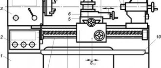
When considering this issue, the first thing that requires primary attention is preparing the equipment for the work, because a surface characterized by high quality processing can only be obtained on a properly functioning machine. It follows from this that before starting machining, you need to check the spindle units and eliminate all shortcomings, if any.
If you plan to turn a part that needs to be supported by the rear center, then the tailstock should also be checked. To check it, centers with vertices are inserted into the spindle and quill, and then the tailstock is gradually moved towards the front. This process continues until the centers touch. The ideal option is that the vertices of the centers coincide. If this condition is not met, then the situation can be corrected by moving the tailstock along the intermediate plate. It is much easier to determine the position of the centers if you place a blank sheet of paper under them.
Fixing workpieces when performing finishing work
When performing finishing work, the workpiece should be secured very carefully to prevent the slightest displacement during machining. Neglect of this condition can lead to rejection of the part manufactured in this way. When turning a surface is carried out without changing the position of the blank, its position can be changed if the fixation is unsatisfactory, causing the axes of the machined surfaces to not coincide, and therefore the finished product will not meet the requirements for it.
If you overdo it when fixing a blank, for example, over-tighten the jaws of a chuck used when cutting a ring with thin walls, upon completion of the work you may find a changed shape of the part. It is recommended to prevent such deviations from the norm by loosening the cams before finishing machining (relevant for cases where rough turning was previously carried out).
Automation of equipment for rough metal processing
Despite the fact that rough metal processing is only a preparatory stage for the main refinement, it is a complex and labor-intensive process. It is for this reason that most of the equipment used in mass production is automated.
Special CNC machines perform even the most complex tasks with minimal human intervention. The operator monitors the execution of all processes and sets the programs for the machines according to which they should work.
In addition, the inclusion of units in an automatic line minimizes or completely eliminates idle workpieces; after pre-processing, they are immediately sent along the conveyor for semi-finishing and finishing.
Also, the use of machines with software helps reduce the energy intensity of processes, since all modern installations are equipped with energy-saving mechanisms.
Scientists are constantly developing new technologies that allow them to perform even the most complex tasks with minimal losses of raw materials and in a short time.
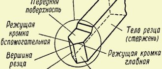
What tool is used for finishing turning?
It is the cutting tool that is responsible for the roughness of the surfaces formed. In order for the resulting part to have a high degree of surface cleanliness, you need to choose the right shape of the cutting tool. An ordinary through cutter is an excellent option that can fulfill the requirements that directly relate to surface roughness.
Turning is often accompanied by tearing out hard inclusions contained in the workpiece material. This leads to the formation of indentations that are unacceptable. To avoid this, you need to use a spring holder. In this case, hard inclusions are not pulled out, but smoothed out.
lecture presentation for a lesson on the topic
Turning
Slide 2
Turning is used to process mainly rotating surfaces, as well as threads and worms using cutters on lathes. processing of external surfaces of rotation is called turning, processing of internal surfaces of rotation is called boring, processing of grooves is called cutting, processing of ends is called trimming, processing of threads is called tapping.
Slide 3
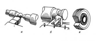
Depending on the type of surface being processed, various types of universal or special cutters are used. Most often, the main rotational movement is imparted to the workpiece, which is installed in centers, in a self-centering chuck, in a chuck and center, in a special or specialized device that is attached to the machine spindle, and feed movements are imparted to the cutter.
Slide 4
Basing Center holes are taken as bases. When processing hollow shafts, they are based on center plugs or conical chamfers of the holes.
Slide 5
Turning Preliminary (60-70% of the total allowance) Final (large V, small S)
Slide 6
Turning on multi-cutting lathes Methods of multi-cutting turning: With longitudinal feed. With cross feed. n S prod S pop
Slide 7
Turning on multi-cutting lathes Methods of multi-cutting turning: With plunging and subsequent longitudinal feed. n The number of cutters in setup is regulated by the rigidity of the workpieces being processed and the power of the machine. Accuracy of single-pass processing – 9-11 quality
Slide 8
Turning has the following disadvantages: 1. Bending of the workpiece being turned under the influence of a unilateral cutting force leads to distortion of the shape of the machined surface, and in some cases to loss of stability of the cutting process (self-oscillations); .
Slide 9
2. When turning steel workpieces at high cutting speeds, hot drain chips are produced, which wrap around the tool, clutter the workspace and pose a serious threat to the worker; .
Slide 10
3. During turning, the cutting part of the cutter is continuously exposed to high forces and high temperatures, which significantly reduces its durability and limits the cutting speed. .
Slide 11
Solution to the disadvantages: When turning long cylindrical surfaces, the first disadvantage is compensated by multi-cutter turning, when the radial cutting forces are balanced. .
Slide 12
The second disadvantage of turning is compensated by the use of various chip breaking methods. They can be divided into two groups. In the first case, chip crushing is achieved by creating certain chip formation conditions. In the second case (kinematic methods), chip crushing occurs due to periodic interruption of the cutting process by superimposing an oscillatory motion parallel to the guide of the machined surface on the feed movement. .
Slide 13
The third disadvantage is compensated by the use of the rotational method, i.e. turning with a rotating cutter with a circular cutting edge. The active section of the cutting blade is continuously renewed and the speed of sliding of the chips and cutting surface along the surfaces of the cutting wedge of the tool is sharply reduced. Rotary cutters can rotate forcibly or due to frictional forces between the tool and the chips (self-rotation). However, only surfaces with a smoothly changing generatrix can be processed in this way. .
Slide 14
Screw-cutting lathes are used for cutting ends, centering, turning external cylindrical surfaces (including eccentric ones), processing through and blind cylindrical holes, turning conical and shaped surfaces, threading and other work. .
Slide 15
When turning, turning is distinguished: a) rough (or roughing) - with processing accuracy IT13...IT12 with surface roughness up to Ra = 6.3 μm; b) semi-finish – IT12...IT11 and roughness up to Ra = 1.6 µm; c) finishing – IT10…IT8 and roughness up to Ra = 0.4 µm. .
Slide 16
When roughing, as with any roughing, up to 70% of the allowance is removed. In this case, the maximum possible cutting depth t and feed S are assigned. In roughing operations, increasing processing productivity is achieved by increasing the cutting depth (reducing the number of working strokes), as well as feed. During finishing operations, the feed is limited by a given surface roughness, so reducing the main time is possible by increasing the cutting speed. .
Slide 17
Trimming the ends (Fig. d) Usually, before turning the outer surfaces of the workpiece, one or both of its ends are trimmed. The ends are trimmed with continuous persistent, bent or scoring cutters with a transverse feed towards or away from the center of the workpiece. The workpiece is usually secured in a chuck or on a faceplate. .
Slide 18
.
Slide 19
When trimming with a feed from the periphery to the center, the end of the workpiece turns out to be concave due to the action of the cutting force components Px and Ru on the cutter. When cutting from the center to the periphery, the end surface becomes less rough and the end is convex. During a repeated pass, the end of the workpiece is flat. When cutting shoulders and ledges with a continuous thrust cutter, they work with both longitudinal and transverse feed. When cutting the right end of the workpiece, use the cut center. .
Slide 20
Centering is used to obtain center sockets in long workpieces. Alignment must be performed very carefully, since the centering sockets are the basis for subsequent processing of workpieces, and are also used when editing and checking manufactured parts. Centering is done using a drill and a countersink or using a combined centering drill. .
Slide 21
Grinding of external cylindrical surfaces is carried out with straight, bent or persistent cutters with longitudinal feed when securing the workpieces in the chuck, on the faceplate, in the chuck and the center, in the centers, on the mandrel and special devices (Fig.a). .
Slide 22
.
Slide 23
Short parts with L/D 10, the workpieces are fastened in the centers (or in the chuck, supported by the center of the tailstock) and are also supported by a steady rest. .
Slide 24
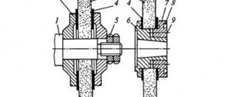
It is advisable to process parts such as bushings, gears, etc., with machined holes, on a mandrel to obtain concentricity of the outer and internal surfaces, as well as to ensure that the end surface is perpendicular to the axis of the part. Mandrel turning is usually used for finishing. .
Slide 25
Smooth shafts are processed by installing the workpiece on the centers. First, one end of the workpiece is turned to the length necessary to install and secure the clamp, and then it is turned 180° and the rest of the part is turned. .
Slide 26
Stepped shafts are turned according to two schemes: dividing the allowance into parts (Fig. b) or dividing the length of the workpiece into parts (Fig. c). In the first case, workpieces are processed with smaller cutting depths, but the overall path of the cutter is large and the main (technological) sharply increases. machine time (To). In the second case, the allowance from each stage is cut off immediately due to the processing of the workpiece with a large cutting depth. In this case, To decreases, but greater machine drive power is required. .
Slide 27
.
Slide 28
It is recommended to process non-rigid shafts with through-thrust cutters with a main entering angle = 90°. When processing shaft workpieces with such cutters, the radial component of the cutting force is Pу = 0, which reduces the deformation of the workpieces. .
Slide 29
Turning fillets and roundings This operation is performed with passing cutters with a rounding between the cutting edges along the appropriate radius with longitudinal feed or special fillet cutters with transverse feed.
Slide 30
Grooving is carried out with a transverse feed by slotted cutters, in which the length of the main cutting edge is equal to the width of the groove being machined. Wide grooves are machined with the same cutters, first with a transverse and then with a longitudinal feed. .
Slide 31
Drilling, countersinking, countersinking and reaming of holes are performed with appropriate tools mounted in the tailstock quill. Shown is a diagram of drilling a cylindrical hole in a workpiece. .
Slide 32
Boring of internal cylindrical surfaces is carried out using boring cutters fixed in the tool holder of the machine, with longitudinal feed. Smooth through holes are bored with continuous boring cutters (Fig. h); stepped and blind cylindrical holes - with persistent boring cutters (Fig. i). Usually, after boring a blind or stepped hole to a given length, turn off the longitudinal feed, turn on the transverse feed, and trim the inner end (bottom) of the hole. .
Slide 33
.
Slide 34
Cutting of processed parts is carried out using cutting tools with transverse feed. The cutter has a long narrow head, to save metal - along the width of the cut. However, as the width of the cutting part decreases, the rigidity and strength of the cutter decreases. For workpieces with a diameter of 30–50 mm, the width of the cutting part of the cutter is 3–5 mm. For better chip removal, a hole is sharpened on the front surface of the cutter, and to reduce friction on the sides, auxiliary angles 1 within 1–2° are used. .
Slide 35
When cutting a part with a cutter with a straight cutting blade (Fig. j), the resulting neck is destroyed, and the end of the finished part has to be additionally trimmed. When cutting a part with a cutter with an inclined cutting blade (Fig. l), the end is clean and no additional trimming is required. When processing workpieces using semi-automatic and automatic machines, the processed parts are cut off from the rod using cutting tools with an inclined cutting blade. .
Slide 36
.
Slide 37
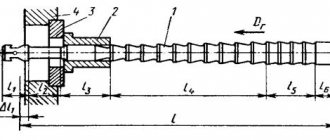
Turning of shaped surfaces of workpieces with a generatrix length of up to 40 mm is carried out using turning shaped cutters. They are divided into rod, round, prismatic and tangential. Long shaped surfaces are processed with pass-through cutters with longitudinal feed using a shaped copier installed instead of a copying cone ruler. .
Slide 38
.
What are cutters made of?
Finish turning is characterized by the removal of small-section chips and increased cutting speeds, during which the tool should not lose its own hardness. In addition, the cutter blade must have sufficient wear resistance.
In accordance with the above requirements, finishing cutters, which are used in working with cast iron and steel, are made of high-speed steel, carbide materials, and mineral ceramics. Today, cermets are increasingly used, which, in addition to aluminum oxide, contain additives of tungsten, molybdenum, titanium and other metals.
Face turning: the optimal tool
To process the end surface of a part, a scoring cutter is most often used. This type of cutting tool is designed specifically for machining open surfaces, such as an end. It is completely unsuitable for trimming the end faces of shafts supported by the rear center. This is due to the specific design of all elements involved in this process. The top of the cutter will not even have time to reach the middle of the surface being processed, since the cutting edge of the tool will rest against the center much faster.
When processing the end of a product, a straight through cutter is installed in a tool holder parallel to the axis of the equipment centers.
Among scoring cutters, there are right- and left-handed types of designs.
Shoulders facing the headstock are machined with left-handed cutters, while right-hand ones are used to turn shoulders that face the tailstock. Go to list of articles >>
Principles of turning
The technology of metal turning involves the use of special machines and cutting tools (cutters, drills, reamers, etc.), through which a layer of metal of the required size is removed from the part. Turning is performed through a combination of two movements: the main one (rotation of the workpiece fixed in a chuck or faceplate) and the feed movement performed by the tool when processing parts to the specified parameters of their size, shape and surface quality.
Due to the fact that there are many techniques for combining these movements, turning equipment is used to work with parts of various configurations, and also carry out a whole list of other technological operations, which include:
- cutting threads of various types;
- drilling holes, boring them, reaming them, countersinking;
- cutting off part of the workpiece;
- turning grooves of various configurations on the surface of the product.
Main types of metal turning work
Thanks to such a wide functionality of turning equipment, you can do a lot with it. For example, it is used to process products such as:
- nuts;
- shafts of various configurations;
- bushings;
- pulleys;
- rings;
- couplings;
- gear wheels.
Naturally, turning involves obtaining a finished product that meets certain quality standards. In this case, quality means compliance with the requirements for the geometric dimensions and shape of parts, as well as the degree of surface roughness and the accuracy of their relative position.
To ensure control over the quality of processing on lathes, measuring instruments are used: at enterprises that produce their products in large series - maximum calibers; for conditions of single and small-scale production - calipers, micrometers, internal gauges and other measuring devices.
Measuring tools often used in turning
The first thing that is considered when learning turning is the technology of metal processing and the principle by which it is carried out. This principle lies in the fact that the tool, cutting its cutting edge into the surface of the product, clamps it. To remove a layer of metal corresponding to the size of such an incision, the tool must overcome the adhesion forces in the metal of the workpiece. As a result of this interaction, the removed layer of metal is formed into chips. The following types of metal shavings are distinguished.
Merged
Such chips are formed when workpieces made of mild steel, copper, tin, lead and their alloys, and polymer materials are processed at high speeds.
Elemental
The formation of such chips occurs when workpieces made of low-viscosity and hard materials are processed at low speed.
Broken shavings
Chips of this type are obtained when processing workpieces made of material characterized by low ductility.
Stepped
The formation of such chips is typical for medium-speed processing of workpieces made of medium-hard steel and parts made of aluminum alloys.
Types of chips during turning