Many home workshops are equipped with welding equipment based on an inverter power supply. Such products have many advantages. However, from time to time any equipment breaks down and repair of welding inverters may be required.
Such an operation can be easily performed at home, since the internal layout of the inverter installation for igniting the arc is easy to diagnose and maintain. The success of correcting inverter welding faults depends, first of all, on the skills and knowledge of the repairman.
Features of welding inverters and their repair
The inverter-type semi-automatic welding machine has a number of features and advantages.
Most users of such welding devices note:
- high installation power;
- mobility of the device;
- ease of maintenance;
- reliability of the inverter design;
- minimum consumption of electrical energy when performing work on welding metal products.
A characteristic feature of inverter welding devices is a more complex electrical circuit compared to transformer or rectifier welding.
Inverter for welding work.
Repair of inverter welding machines should begin by checking the following elements:
- transistors;
- diode bridge;
- cooling system.
Before you repair welding machines yourself, you need to diagnose the main components. Typically, faulty parts, such as transistors or diodes, can be easily identified by a significant change in geometry.
If such parts can be identified visually, then restoring a welding machine with your own hands will come down to a banal replacement of faulty electrical elements using a soldering iron and solder.
Do-it-yourself repair of semi-automatic welding machines should be carried out by craftsmen who have at least basic knowledge of electronics and know how to use devices such as a multimeter, voltmeter and oscilloscope.
Most models of inverter welding machines come with instructions. It is easier to carry out maintenance of these devices using the diagrams available in the corresponding section of the documentation.
We restore the operation of the welding inverter Resanta SAI-250PN
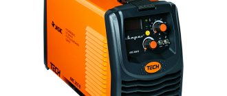
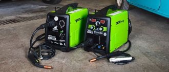
One day I came across a Resanta SAI 250PN welding inverter.
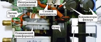
The device, without a doubt, inspires respect. Those who are familiar with the design of welding inverters will appreciate all the power from the appearance of the electronic filling.
As already mentioned, the filling of the welding inverter is designed for high power. This can be seen from the power part of the device.
The input rectifier has two powerful diode bridges on the radiator, four electrolytic capacitors in the filter. The output rectifier is also fully equipped: 6 dual diodes, a massive choke at the rectifier output.
three ( ! ) soft start relays. Their contacts are connected in parallel to withstand the large current surge when welding is started.
If we compare this Resanta (Resanta SAI-250PN) and TELWIN Force 165, then Resanta will give it a head start.
But even this monster has an Achilles heel.
The device does not turn on;
The cooling cooler does not work;
There is no indication on the control panel.
After a quick inspection, it turned out that the input rectifier (diode bridges) were in good condition, the output was about 310 volts. Therefore, the problem is not in the power part, but in the control circuits.
An external inspection revealed three burnt-out SMD resistors. One in the gate circuit of the 4N90C field-effect transistor at 47 Ohms (marked - 470 ), and two at 2.4 Ohms ( 2R4 ) - connected in parallel - in the source circuit of the same transistor.
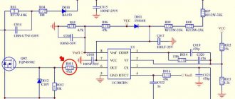
The 4N90C transistor ( FQP4N90C ) is controlled by the UC3842BN . This microcircuit is the heart of a switching power supply, which powers the soft start relay and the +15V integrated stabilizer. It, in turn, powers the entire circuit, which controls the key transistors in the inverter. Here is a piece of the Resanta SAI-250PN diagram.
It was also discovered that the resistor in the power supply circuit of the PHI controller UC3842BN (U1) was also broken. In the diagram it is designated as R010 ( 22 Ohm , 2W ). On the printed circuit board it has the position designation R041. I will warn you right away that it is quite difficult to detect a break in this resistor during external inspection. A crack and characteristic burns may be on the side of the resistor that faces the board. This was the case in my case.
Apparently, the cause of the malfunction was the failure of the UC3842BN (U1) PHI controller. This in turn led to an increase in current consumption, and resistor R010 burned out from a sudden overload. SMD resistors in the circuits of the MOSFET transistor FQP4N90C played the role of a fuse and, most likely, thanks to them the transistor remained intact.
As you can see, the entire switching power supply on the UC3842BN (U1) has failed. And it powers all the main blocks of the welding inverter. Including the soft start relay. Therefore, the welding did not show any “signs of life.”
As a result, we have a bunch of “small things” that need to be replaced in order to revive the unit.
After replacing the indicated elements, the welding inverter turned on, the value of the set current appeared on the display, and the cooling cooler began to make a noise.
For those who want to independently study the design of a welding inverter, here is a complete schematic diagram of the Resanta SAI-250PN.
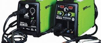
The welding inverter type resanta SAI 190, like all others, has significant advantages compared to a conventional welding machine. Thanks to the mobility and small weight of the resant, ordinary welding units have been forced out of the market. There are cases of inverter failure, and for this you need to know the principle of operation, structural diagram and malfunctions of the Resanta Sai 190.
Diagnosis of inverter faults
Immediately before restoring the functionality of inverter welding equipment, you should familiarize yourself with typical faults and the most effective diagnostic methods.
In most cases, repair of semi-automatic welding machines should be carried out according to the following algorithm:
- Visual inspection of all inverter components.
- Cleaning oxidized contacts using a solvent and a brush.
- Studying the design of the inverter using the documentation included in the kit.
- Fault diagnosis.
- Replacement of non-working electronic components.
- Test run.
Functional diagram of a welding inverter.
All malfunctions that may require DIY repair of welding machines are divided into three types:
- arising due to incorrect choice of welding mode;
- arising due to a malfunction of one of the elements of the electronic circuit of the device;
- caused by dust or foreign objects entering the housing of the inverter power supply.
Before checking the welding machine for faulty radio components, you should completely clean it of dust and dirt. Clogging of the cooling elements of the arc support system can adversely affect the performance of many electronic components.
If a preliminary visual check does not reveal any malfunctions, then you should proceed to a more in-depth diagnosis.
Typical reasons for inverter failure are presented:
- liquid entering the inverter housing, resulting in oxidation of the conductive paths and corrosion of the main radio elements;
- an abundance of dust and dirt inside the case, as a result of which the cooling significantly deteriorated and the power microcircuits overheated;
- overheating of the inverter due to the selection of an incorrect operating mode, which may require repair of welding rectifiers.
Repairing a welding transformer, unlike an inverter, can be performed without significant skills and abilities. Transformer assemblies use radioelements that have an incredibly long life cycle.
The repair technique for the converter and other key components of the inverter current source will be shown in the next section.
Basic malfunctions of the welding inverter
Welding inverter sparks, but does not weld
This malfunction is quite common in budget models. The equipment generates a discharge, but an electric arc does not ignite. More precisely, it lights up for a very short period of time and immediately goes out. There are several explanations for this breakdown.
Troubleshooting should begin by checking the welding cables. As practice shows, in most cases the reason lies precisely in them. Even in the case when obvious sins were not found, you should not calm down. It is advisable to take new conductors and try to ignite the arc again. If nothing has changed, then you need to make sure that all connectors are secure.
Also, the reason may lie in the electrolytic capacitors that are used in the converter circuit. They are easy to replace yourself. If you don’t have the skills, you can turn to more experienced friends or specialists. When the situation has not improved, then it’s time to pay attention to the wires of the package. It may be that they are burnt and require replacement.
If in this case it was not possible to repair the welding machine, then it should be taken to a service center. There can be many reasons for such a problem, and it is very difficult to find them by brute force. Having carried out diagnostics, specialists will be able to quickly determine the breakdown and offer options for its elimination.
The welding machine turns on, but does not weld
Sometimes a situation arises when the inverter is connected to the network, but does not generate a welding arc. All indicators and devices show that they are working normally, but the device itself does not cook at this time. The most likely reason is that the device has overheated. This will be discussed below.
Another reason could be faulty cables. It is worth trying to connect new lines and try to remove the welding arc again.
Main types of breakdowns and their elimination
Before considering the main types of malfunctions of inverter devices, you should familiarize yourself with the inverter device.
Electrical circuit of a welding inverter.
Most popular models consist of:
- power supply;
- control unit;
- power block.
Malfunctions and repairs of welding machines in most cases are associated with a breakdown of the power unit, consisting of:
- Primary and secondary rectifiers. The block includes two diode bridges of varying power. The first bridge is capable of withstanding up to 40 amperes of current and up to 250 volts of voltage. The second diode bridge is assembled from more powerful elements and is capable of maintaining a current of 250 amperes at a voltage of about 100 volts. Possible errors of this module are associated with failure of the diodes of the primary or secondary bridge.
- Inverter converter. A breakdown of the power transistor of the inverter converter is often the answer to the question why the welding machine does not weld. The inverter can be repaired by replacing the transistor with an analogue one with a current rating of 32 amperes and a voltage of 400 volts.
- High frequency transformer. Typically, a transformer consists of several windings that increase the current to 250 amperes at a voltage of up to 40 volts. Most inverter equipment has two windings made using copper wire or tape.
Before you repair welding machines with your own hands, you should carefully diagnose the device and clearly determine which of the elements is faulty.
You shouldn’t even try to repair an inverter yourself from which thick white smoke is pouring out of the housing. In such cases, the best solution would be to contact a qualified repair center.
Layout of welding inverter parts.
Repair of a semi-automatic welding machine with an inverter source may be necessary if the following malfunctions occur:
- Unstable burning of a hot arc or strong spattering of the electrode material. The malfunction in most cases is due to the incorrect choice of operating current. The operating instructions say that per 1 millimeter of electrode diameter there should be a current of 20 to 40 amperes.
- Adhesion of welding to metal. This behavior is typical for devices operating at insufficient voltage. Such malfunctions and methods for eliminating them are clearly described in the accompanying documentation. If the electrode sticks to the material being welded, clean the terminal contacts to which the inverter device modules are connected. In addition, it would not be superfluous to measure the voltage in the electrical network.
- No arc when turning on the equipment. The defect is often associated with simple overheating of the device or damage to the power cables during long-term operation at elevated temperatures.
- Inverter emergency shutdown. If during the work the device suddenly turns off, then the short circuit protection between the wires and the housing has probably worked. Repairing the device in the event of such a defect consists of finding and replacing damaged elements of the inverter power circuit.
- Huge consumption of electric current during idle operation. A typical malfunction that occurs due to the short circuit of the turns on the current-carrying coils. Restoring the device's functionality after such a malfunction consists of completely rewinding the coils and applying a layer of additional insulation.
- Switching off welding equipment after a certain period of time. This behavior is typical for overheating inverter electrical appliances. If the welding suddenly turns off, then you need to let it cool down and after 30-40 minutes you can continue working.
- Extraneous sounds when the power supply is operating. Elimination of the defect consists of tightening the bolts holding together the magnetic guide elements. In addition, the malfunction may be due to a defect in the core fastener or a short circuit between the cables.
It is important to note that most types of work should be performed using a soldering iron equipped with a special suction unit. Such a tool greatly facilitates the work of applying and removing solder to the seats of radio engineering elements.
Recommendations for DIY repairs
Electrical circuit of the welding machine.
When repairing inverter-type welding machines, you should adhere to a certain algorithm:
- If a malfunction occurs, you must immediately disconnect the electrical device from the network, allow it to cool, and only then open the metal casing.
- Diagnostics must begin with a visual inspection of the electrical components of the inverter. There are often cases when repairing an inverter welding machine involves simply replacing damaged parts or soldering conductive contacts. Visually enlarged capacitors or cracked transistors should be replaced first.
- If a visual inspection fails to determine the cause of the malfunction of the welding machine, you must proceed to checking the parameters of the parts using a multimeter, voltmeter and oscilloscope. The most common failures of power units are associated with malfunction of transistors.
- After replacing the electrical elements, it is worth moving on to checking the printed conductors located on the inverter board. If you find torn or damaged tracks on the printed circuit board of a welding tool, you must immediately eliminate the defect by soldering jumpers or restoring the tracks using copper wire of the required cross-section.
- After completing work with the tracks, it makes sense to move on to servicing the connectors. If the inverter device stopped working gradually, then there may be poor contact in the connecting connectors. In this case, it is enough to measure all contacts with a multimeter and clean the connectors with an ordinary household eraser.
- Despite the fact that malfunctions of a welding inverter are rarely associated with diode bridges, it would be a good idea to check their performance. It is better to diagnose this electrical element in a soldered state. If all the legs of the bridge are short-circuited, then you should search for the faulty diode and replace it.
- The last step in inverter repair is checking the board and control panels. Diagnostics of all components of the board should be carried out using a high-resolution oscilloscope.
If the diagnostics have been carried out, but it was not possible to find out what is broken in the welding machine, you should stop doing independent repairs and contact specialized workshops.
When performing independent repair work, you should not forget about the safety rules:
- Do not use electrical appliances without a protective top casing;
- all diagnostic and repair work should be carried out on completely de-energized equipment;
- It is safest to remove accumulated dust and dirt using an air flow generated by a compressor or a compressed gas cylinder;
- Cleaning of printed circuit boards must be done using neutral solvents applied to a special brush;
- Long-term storage of electrical appliances should be done in dry rooms and completely switched off.
Most inverter electrical appliances are supplied complete with accompanying documentation. In these papers you can find a description of the most common faults and repair methods. Therefore, if malfunctions occur, you should carefully study the documentation and only then begin repair work.
Inverter type welder
Old transformer modifications of the welding machine have a very low price, high repairability, but have significant disadvantages: dimensions, significant weight and dependence on the mains voltage. The output current of the electronic meter is limited by electricity consumption to 4.5 kW. For welding work when using thick metals, current consumption increases, and this process places a significant load on old power lines, which also contain strands (after all, in the former CIS countries they are rarely replaced with new ones).
They have been replaced by inverter-type welding machines, the operating features of which are significantly different.
Features of operation
The scope of application is varied, ranging from households to enterprises. The main task is to ensure stable combustion and maintenance of the welding arc when performing welding work, thanks to the use of high frequency current. The operation of the welding inverter is based on the principles:
- Conversion of alternating input voltage 220 V to direct (direct current is converted into high-frequency alternating current of a non-sinusoidal nature).
- Subsequent rectification of the high-frequency current (frequency is maintained).
Thanks to these principles, there is a significant reduction in the weight and dimensions of the inverter, which makes it possible to additionally integrate cooling.
Operating principle and main characteristics
To troubleshoot inverter welding machines, you need to familiarize yourself with its block diagram. It consists of the following elements:
- Rectifier.
- Inverter.
- Transformer.
- High frequency rectifier.
- Control and stabilization circuit (driver and control board).
- Welding current regulator.