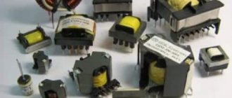
When it comes to transformers and their types, all models still have similar functionality; the only way transformers can differ from each other is the scope of application and the materials chosen to complete the product. In the assortment of power elements, the toroidal transformer, characterized by successful design capabilities and good performance, takes pride of place. And the most important difference between a toroidal transformer and all other types is that the core or magnetic circuit of the product is formed in the form of a ring. However, we will consider all other technical advantages and areas of application further in more detail in the article.
What are the purpose and functionality of toroidal transformers?
- power and measuring;
- increasing or decreasing.
Such power elements are capable of converting electricity, affecting voltage or current to varying degrees.
Where and for what is a toroidal transformer used?
The power toroidal transformer has a wide range of applications, both in industrial and domestic environments. So, many ordinary people don’t think about it, but toroidal transformers literally surround us, providing us with comfort and coziness in our houses and apartments. Firstly, low-frequency transformers are involved in the formation of the power system and all major communications, not excluding ordinary sockets. Secondly, in the circuits of an uninterruptible power supply for a computer and smartphone, you can also find a transformer, which is considered an indispensable element of the circuit.
And in the field of radio engineering, electronics, and engineering one cannot do without toroidal transformers. It is obvious that such important power elements are used to create a safe and efficient power source for lighting equipment and the operation of modern medical and diagnostic equipment.
In an industrial environment, a toroidal transformer is calculated and implemented in the configuration of welding equipment circuits.
What technical advantages do toroidal transformers have?
- Cost-effective performance of a power element with a ring magnetic core. Internally, power transmission occurs with smaller size and weight.
- Compactness and small volumes of the product. That is, winding a toroidal transformer performs its task without failure, but the transformer itself is half the size compared to other models.
- Easy to install and operate. Undoubtedly, transformers with a ring core are very easy to install in the position specified according to the circuit, connect, and test before the first operational start-up. And it doesn’t matter where the installation is planned - inside or outside.
- Saving electrical impulse. About a third of the energy produced is retained both at full load and at idle.
- High thermal load capacity. The shape of the magnetic circuit – a toroid – contributes.
With so many technical advantages, the toroidal transformer wins in many respects. For example, compared to armored and rod transformers, it has low dissipation rates, therefore it is safe and simply indispensable for sensitive electronic equipment.
Let's consider how to calculate the power of a transformer
First, we determine the cross-section of the base. The magnetic core must not only withstand a magnetic field of a certain intensity, it also dissipates the generated heat. There is a simplified method for calculating the cross-sectional area in cm². It is equal to the square root of the required power value in watts.
This is the maximum value; a real transformer should have a margin of +50%. Otherwise, the core will fall into the region of magnetic saturation, which will lead to sudden local heating. For toroidal cores, a margin of 30% of the calculated area is sufficient.
Next, you need to know how to determine the wire parameters for the windings in order to ensure the design power of the transformer. The first value is the number of turns per volt (we are talking about the primary winding).
To do this, we will use a simple formula: divide the constant 60 by the cross-sectional area in cm². For example, the cross-section of the magnetic circuit is 6 cm². This means that for every volt of input voltage, 10 turns of wire are required. That is, with a power supply of 220 volts, the primary winding will consist of 2200 turns.
The calculation of secondary windings is made in proportion to the transformation ratio. If 20 volts of output are required, at a constant of 10 turns per volt, 200 turns of secondary winding will be required. This is an absolute value, excluding load losses. We obtain the true number of turns by multiplying the value by 1.2.
Before winding the transformer, you need to know the cross-section of the wire. The minimum wire diameter is calculated using the formula: D=0.7*√I
Important! The diameter of the conductor is measured without taking into account the thickness of the insulating varnish. It must be washed off with acetone at the measurement site. This is true for wires with a small cross-section.
√I – square root of the current value in amperes
There is no need to skimp on wires. A smaller diameter does not dissipate heat well and the winding may burn out. The thinner the wire, the higher the resistance. Possible power losses and reduction in design characteristics.
How it works
The design is similar to the armored one, the magnetic field is single-turn, and accordingly the power is less. It also has a collapsible design. The efficiency of using the surface of the magnetic circuit is not higher than 40%.
Expert opinion
It-Technology, Electrical power and electronics specialist
Ask questions to the “Specialist for modernization of energy generation systems”
Let's look at how to calculate the power of a transformer. Toroidal cores are made of magnetic coiled transformer steel with very low loss levels and high saturation induction. Ask, I'm in touch!
What are the advantages of a toroidal transformer core?
Recall that the core or magnetic circuit of the toroidal transformer 220 is manufactured in the form of a ring. And this is almost an ideal form in physical terms. For its production, tape-shaped permalloy is most often used in production, and the material consumption is small, and rejection and trimming on the conveyor is reduced. At the second stage of the sequential manufacturing of the transformer, a winding is applied to its core and distributed evenly without flaws over a given surface. The length of the winding wires is short, so the resistance force in the segment is also reduced. And this provides the toroidal transformer with high efficiency. The core of the toroidal transformer itself plays an important role in this.
Recommendations
- Griffiths, David (1989), Introduction to Electrodynamics
, Prentice-Hall, ISBN 0-13-481367-7 - Holliday; Resnik (1962), Physics, Part Two
, John Wiley and Sons - Haight, William (1989), Engineering Electromagnetics
(5th ed.), McGraw-Hill, ISBN 0-07-027406-1 - Purcell, Edward M. (1965), Electricity and Magnetism
, Berkeley Physics Course,
II
, McGraw-Hill, ISBN 978-0-07-004859-1 - Reitz, John R.; Milford, Frederick J.; Christie, Robert W. (1993), Foundations of Electromagnetic Theory
, Addison-Wesley, ISBN 0-201-52624-7
What must be taken into account when calculating a toroidal transformer
In order to apply the standard physical formula, you first need to know the parameters of the voltage that will be supplied to the primary winding of the product (symbol for the formula - U), the outer and inner diameter of the core or magnetic circuit (symbol for calculations - D and d), and, The main thing is not to forget about the thickness of the magnetic circuit - H.
An important indicator is the area of the core window (previously recorded in the records - S). The intensity of excess heat removal largely depends on it. These core gap areas range from 80 to 100 cm, and the cross-section is half as large.
Just in case, let us remember the calculation formulas in the article: S0 = * d2 / 4., Sc = H * (D – d)/2.
Complete limitation of the B field by toroidal inductors
| This article provides insufficient context for those unfamiliar with the subject . |
In some cases, the current in the winding of a toroidal inductor contributes only to B
field inside the windings and does not contribute to the magnetic
B
field outside the windings. This is a consequence of symmetry and Ampere's law of rotation.
Sufficient conditions for complete internal confinement of field B
| Rice. 1. Coordinate system. The Z axis is the nominal axis of symmetry. The X axis is chosen arbitrarily to correspond to the starting point of the winding. ρ is called the radial direction. θ is called the circumferential direction. | Rice. 2. Axisymmetric toroidal inductor without circumferential current. |
The absence of circumferential current [4] (the path of the circumferential current is indicated by a red arrow in Figure 3 of this section) and the axisymmetric arrangement of conductors and magnetic materials. [4][5][6] are sufficient conditions for the complete internal constraint of B
field.
(Some authors prefer to use the HOUR
field.)
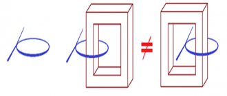
Because of symmetry, the flux lines B must form circles of constant intensity centered on the axis of symmetry. The only B flux lines that carry any current are those inside the toroidal winding. Therefore, from Ampere's winding law, the field strength B must be zero outside the windings.[6] Rice.
3. Toroidal inductor with circumferential current. Figure 3 in this section shows the most common toroidal winding. This does not meet both requirements for complete B field limitation. When viewed from the axis, sometimes the winding is inside the core and sometimes outside the core. In the near region it is not axisymmetric. However, at points located at a distance several times greater than the distance between the windings, the toroid actually appears symmetrical.[7] The problem of circumferential current remains. No matter how many times the winding wraps around the core and how thin the wire is, this toroidal inductor will still include a single-coil loop in the plane of the toroid. This winding will also produce and be susceptible to E
field in the plane of the inductor.
Figures 4-6 show various methods for neutralizing the circumferential current. Figure 4 is the simplest and has the advantage that the return wire can be added after purchasing or assembling the inductor.
| Rice. 4. Circumferential current opposing the return wire. A white wire runs between the outer rim of the inductor and the outer part of the winding. | Rice. 5. Circumferential current opposing the return winding. | Rice. 6. Circumferential current opposing the divided return winding. |
E field in the toroid plane
| Rice. 7. A simple toroid and the generated E-field. Excitation of ±100 volts is acceptable. | Rice. 8. Voltage distribution with reverse winding. Excitation ± 100 Volts is allowed. |
There will be a potential distribution along the winding. This may lead to E
-Field in the plane of the toroid, as well as the susceptibility to
E
field in the plane of the toroid, as shown in Figure 7. This can be reduced by using a return winding, as shown in Figure 8. In this winding, each place where the winding crosses itself, two parts will have equal and opposite polarity, which significantly reduces the field E generated in the plane.
Toroidal inductor/transformer and vector magnetic potential
Main article: Magnetic vector potential
Shows the development of the magnetic vector potential around a symmetrical toroidal inductor.
See Feynman Chapter 14.[8] and 15[9] for a general discussion of the magnetic vector potential. See Feynman page 15-11. [10] for a diagram of the magnetic vector potential around a long thin solenoid, which also exhibits complete internal limitation B
field, at least in the infinite limit.
B A
the field is exact using the assumption b f A = 0 {displaystyle bf {A} = 0} . This would be true under the following assumptions:
- 1. Coulomb gauge is used
- 2. Lorentz sensor is used and there is no charge distribution, ρ = 0 {displaystyle ho = 0,}
- 3. Lorentz sensor is used and zero frequency is assumed
- 4. A Lorentz sensor is used and a non-zero frequency low enough to neglect 1 c 2 ∂ ϕ ∂ t {displaystyle {frac {1} {c^{2}}} {frac {partial phi} {partial t}}} is assumed.
Number 4 will be assumed for the rest of this section and can be referred to as the "quasi-static state".
Although an axisymmetric toroidal inductor without circumferential current completely limits B
the field inside the windings
And
the field (magnetic vector potential) is not limited.
Arrow No. 1 in the figure depicts the vector potential on the axis of symmetry. The radial current sections a and b are at equal distances from the axis, but are directed in opposite directions, so they cancel. Segments c and d are canceled in the same way. Virtually all radial current segments are cancelled. The situation is different with axial currents. The axial current on the outside of the toroid is directed downward, and the axial current on the inside of the toroid is directed upward. Each segment of the axial current on the outer side of the toroid can be associated with an equal but oppositely directed segment on the inner side of the toroid. The segments inside are located closer to the axis than the segments outside, so there is a net upward component of the A
field along the axis of symmetry.
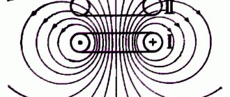
Representation of the fields of magnetic vector potential (A), magnetic flux (B) and current density (j) around a toroidal inductor of circular cross-section. Thicker lines indicate field lines with higher average intensity. The circles in the cross section of the core represent the flow B coming out of the picture. Plus signs on another section of the core indicate flux B. Div A
= 0 was accepted.
Since the equations ∇ × A = B {displaystyle abla imes mathbf {A} = mathbf {B}} , and ∇ × B = μ 0 j {displaystyle abla imes mathbf {B} = mu _ {0} mathbf {j}} ( under the assumption of quasi-static conditions, i.e. ∂ E ∂ t → 0 {displaystyle {frac {partial E} {partial t}} ightarrow 0} ) of the same shape, then the lines and contours of A
is to
B
as the lines and contours
of B
are to
j
.
Thus, the image of the A
field around a
B
loop (as in a toroidal inductor) is qualitatively the same as
the B
field around a current loop.
The figure on the left is an artist's image of A
field around a toroidal inductor.
Thicker lines indicate paths with higher average intensity (shorter paths have higher intensity, so the path integral remains the same). The lines are simply drawn to look good and give the overall appearance of the A
field.
Toroidal action of a transformer in the presence of full field limitation B
In E
and
B
fields can be calculated from
A
and ϕ {displaystyle phi,} (scalar electric potential) fields
B = ∇ × A. {displaystyle mathbf {B} = abla imes mathbf {A}.} [11] and : E = − ∇ ϕ − ∂ A ∂ t {displaystyle mathbf {E} = -abla phi — {frac {partial mathbf {A}} {partial t}}} [11] and so, even if the area outside the windings is devoid of the B
field, it is filled with a non-zero
E
field. The quantity ∂ A ∂ t {displaystyle {frac {partial mathbf {A}} {partial t}}} is responsible for the desired magnetic field coupling between the primary and secondary windings, while the quantity ∇ ϕ {displaystyle abla phi,} is responsible for the undesirable connection of the electric field between the primary and secondary windings. Transformer designers try to minimize electric field coupling. For the rest of this section, ∇ ϕ {displaystyle abla phi,} will be assumed to be zero unless otherwise noted.
Stokes' theorem applies[12] so that the path integral A
is equal to the applied
B
, just as the path integral of
B
is equal to a constant times the applied current
Path integral E
along the secondary winding gives the induced emf of the secondary winding (electromotive force).
EMF = ∮ p a t h E ⋅ d l = − ∮ p a t h ∂ A ∂ t ⋅ d l = − ∂ ∂ t ∮ p a t h A ⋅ d l = − ∂ ∂ t ∫ s you r a c e B ⋅ ds {displaystyle mathbf {EMF} = oint _ {path} mathbf {E} cdot {m {d}} l = -oint _ {path} {frac {partial mathbf {A}} {partial t}} cdot {m {d }} l = — {frac {partial} {partial t}} oint _ {path} mathbf {A} cdot {m {d}} l = — {frac {partial} {partial t}} int _ {surface} mathbf {B} cdot {m {d}} s}
where it is said that the emf is equal to the rate of change with time of the flux B contained in the winding, which is the usual result.
Toroidal transformer Poynting vector coupling from primary to secondary with full field limitation B
In this figure, the blue dots indicate where flux B from the primary current exits the image, and the plus signs indicate where it enters the image.
Explanation of the picture
This picture shows half of a toroidal transformer. Quasi-static conditions are assumed, so the phase of each field is the same everywhere. The transformer, its windings and everything else are located symmetrically relative to the axis of symmetry. The windings are such that there is no circumferential current. Requirements for complete internal insulation B
field due to the primary current.
The core and primary winding are represented by a gray-brown torus. The primary winding is not shown, but the winding current on the cross-sectional surface is shown as gold (or orange) ellipses. In B
, the field caused by the primary current is completely confined to the area surrounding the primary winding (i.e., the core).
The blue dots on the left cross section indicate that line B
core flow exits the left cross section.
In the other section, blue plus signs indicate that B
flow is entering there.
In E
, the field arising from the primary currents is shown by green ellipses.
The secondary winding is shown as a brown line running straight along the axis of symmetry. In normal practice the two ends of the secondary winding are connected together by a long wire which is located a considerable distance from the torus, but to maintain absolute axial symmetry the whole apparatus is treated as being inside a perfectly conducting sphere with a secondary wire "grounded" to the inside of the sphere at each end. The secondary winding is made of resistance wire, so there is no separate load. In E
, the field along the secondary causes a current in the secondary (yellow arrows), which causes
a B
field around the secondary (shown by blue ellipses).
This B
field fills the space, including inside the transformer core, so the end result is a continuous non-zero
B
field from the primary to the secondary unless the secondary circuit is open.
The cross product of the E
field (derived from the primary currents) and
the B
field (derived from the secondary currents) forms the Poynting vector, which is directed from the primary to the secondary.
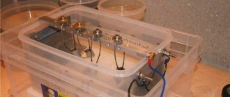
Is it possible to make a toroidal core yourself?
A geometrically correct toroidal core is not so easy to reproduce independently, especially by novice inventors. Firstly, you need to have at your disposal a special permalloy tape, also sometimes called transformer steel. Secondly, familiarize yourself with the rules for forming a torus of rectangular cross-section. The actions are familiar - you need to roll the material into a roll. Actions are consistent and careful, if necessary, go back a step.
A special wooden shuttle with technical semicircular cutouts can be a help in this matter, especially if you need to calculate how much material is needed for winding. The wire for the winding is always taken with an allowance. Recommended reserve is 20-30%.
Thus, it becomes clear that a toroidal transformer can give a head start to other existing power elements. And all because it is simple, reliable and functional. The existing core is created in an advantageous form, which is easy to work with not only at the stage of product manufacture, but also during installation, operation and repair. It is possible to make such a transformer yourself, but this will require perseverance, knowledge, the desire to create a product, the desire to make calculations and look for alternatives.