Characteristics of extraction operations
Drawing is the process of turning a flat or hollow workpiece into an open-top hollow product, carried out using drawing dies. Based on the shape and technological features of sheet stamping, hollow parts produced by drawing can be divided into several main groups:
1) parts having the shape of a body of revolution;
2) box-shaped parts;
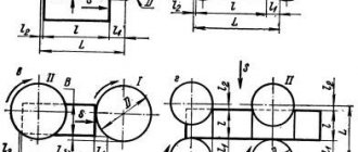
Rice. 1. Hollow parts of various shapes (a-l), obtained by drawing
Parts that have the shape of a body of revolution can be with or without a flange, with a flat or shaped bottom (Fig. 1, a-e).
Box-shaped parts can have square, rectangular, curved side walls with or without a flange; their bottom can be flat or shaped (Fig. 1, f-h).
Parts of complex shape can be semi-symmetrical, having only one plane of symmetry (the body and roof of the car cabin, Fig. 1, i), and asymmetrical (the wing of the car, Fig. 1, j).
Depending on the shape of the part, the workpiece is either drawn in its pure form or drawn in combination with forming, bending and crimping, or flanging.
Extraction is carried out on double- and triple-acting crank presses, double-acting rocker presses with a movable lower table, single-acting (single-stroke) crank presses with a pneumatic or hydropneumatic device (cushion), as well as on single- and double-acting hydraulic presses.
Rice. 2. Scheme of the drawing process: d1 - diameter of the hollow workpiece after
first operation; d2 - diameter of the hollow workpiece after the second operation
A special group consists of wrapping operations—the production of hollow parts of a curved shape by stretching the material and wrapping it around a special wrapping template—a block (Fig. 1, l). The wrapping is done on special wrapping hydraulic presses.
According to the nature and degree of deformation, they distinguish: 1) drawing without thinning the walls; 2) a hood with thinning walls (broach) and 3) a combined hood.
In the first case, drawing occurs without a predetermined change in the thickness of the product wall material, but with a significant reduction in the diameter of the workpiece; in the second, drawing is carried out due to a predetermined reduction in the wall thickness of the drawn semi-finished product with a slight decrease in its diameter. Combined drawing is characterized by a simultaneous significant reduction in the diameter and wall thickness of the drawn semi-finished product.
Depending on the relative thickness of the workpiece or semi-finished product, drawing is carried out with or without the use of a clamp. Since during drawing the material of the workpiece 3 is drawn in by a punch 2 with a rounding rп of a larger diameter D into a matrix 1 with a rounding rm having a smaller diameter d (Fig. 2, a), it is natural that folds (corrugations) form along the edge of the elongated cap due to the presence of excess material or the so-called characteristic triangles b, b1, b2, . bn (Fig. 2, b), because to form a hollow cap with a diameter d and a height h, it would be enough to have a workpiece with a diameter D' without shaded areas. The presence of excess triangles leads to the need to displace and move the metal when drawing upward. In Fig. 2, c shows the drawing in the second operation from a hollow workpiece 4.
Rice. 3. Hood with material pressing
The formation of folds is caused by the stress-strain state of the metal, which, under certain geometric relationships, leads to loss of stability of the workpiece (Fig. 2, a).
To prevent the formation of folds, a pressure ring or fold holder 3 is used, which presses the workpiece flange against the matrix 1 in such a way that the material is not able to form folds, but is forced to move under the pressure of the punch 2 in the radial direction. Material clamping is used both for the first drawing operation, i.e., when drawing a part from a flat workpiece (Fig. 3, a), and during subsequent drawing operations from a hollow workpiece (Fig. 3, b).
Drawing without clamping is used in the manufacture of shallow vessels or products made of thick materials, when folds are almost not formed or are smoothed out when passing through the drawing matrix.
Stress-strain state of metal when drawing hollow bodies
When drawing, a flat workpiece with diameter D (Fig. 4), moving during drawing, changes its dimensions and occupies a number of intermediate positions. In this case, the material of the deformed workpiece in its different parts is under different conditions. In the case of drawing with a clamp without thinning the material and with a gap greater than the thickness of the workpiece (for the case of axisymmetric deformation in the polar coordinate system), the following stress-strain state diagram can be adopted (Fig. 4).
Rice. 4. Scheme of the stress-strain state of individual
areas of the workpiece during drawing (σ - stress, ε - deformation)
1. The bottom of a partially formed hollow cylinder - cap (element a) is in a plane-stressed and volumetric-strained state. Since the deformation of the metal - bilateral uniform stretching in the bottom plane and axial compression is only 1-3% in the first operation, they can practically be neglected. With a multi-operational drawing process, after the second or third operation, the thickness of the bottom noticeably decreases, since the metal from the bottom gradually enters the zone of maximum thinning (at the bottom rounding); The intensity of the bottom thinning is especially evident in brass, which has a small concentrated narrowing deformation (compared to steel).
2. The cylindrical part of the hollow body, located in the gap between the matrix and the punch (element b), can be considered to be in a linearly stressed and volumetrically deformed state. Directly at the bottom rounding of the product (element c), stresses arise in the metal in the form of biaxial tension and uniaxial compression, leading to significant stretching and thinning of the walls in this place. As a result, the cross section of the body here is the least strong and the most dangerous from the point of view of separation of the bottom from the walls of the product. This is a dangerous cross-section and limits the possibility of maximizing the use of the plastic properties of the stamped metal.
3. The part located at the rounding of the working edges of the matrix (element d) experiences complex deformation caused by simultaneous bending and straightening of the workpiece, the greatest radial (meridional) stretch and slight tangential (circumferential) compression.
4. The part of the workpiece located under the clamping ring (element e) is in a volume-stressed and volume-strained state. However, with a sufficiently strong clamping, we can assume εп (εz) = 0. In the planes of the workpiece flange, radial (meridional) tensile stresses σр and tangential (circumferential) compressive stresses σθ arise, and in the direction perpendicular to it - axial compressive stresses σn (σz), and due to the small value of σn, in practice it is often neglected (when a clear wedge section is formed in the flange σn = 0).
Rice. 5. Curve of changes in wall thickness in different parts of the hood during drawing
The meridional tensile stresses σp caused by the pressure of the punch at the edge of the workpiece are equal to zero; As they move away from the edge of the workpiece towards the center of the matrix, they increase, reaching their greatest value at the entrance edge of the matrix. Tangential compressive stresses σθ, on the contrary, are greatest at the outer edge, and their values decrease as they move away from the edge of the workpiece. At the moment when the edge of the workpiece moves by an amount equal to 39% of the workpiece radius (0.39 R), σθ becomes equal to σp. Under the influence of tangential compression stresses, the workpiece flange thickens (sometimes forming a kind of wedge section) and hardens; with insufficient pressure and thin material [(s/D) 100 _ _ _ _ _ _ _ _ _ _ _ _ _ _ _ _ _ _ _ _ _ _ _ _ _ _ _ _ _ _ _ _ _ _ _ _ _ _ _ _ _ _ _ _ _ _ _ _ _ _ _ _ _ _ _ _ _ _ _ _ _ _ _ _ _ _ _ _ _ _ _ _ _ _ _ _ _ _ _ _ _ _ _ _ _ _ _ _ _ _ _ _ _ _ _ _ _ _ _ _ _ _ _ _ _ _ _ _ _ _ _ _ _ _ _ _ _ _ _ _ _ _ _ _ _ _ _ _ _ _ _ _ _ _ _ _ _ _ _ _ _ _ _ _ _ _ _ _ _ _ _ _ _ _ _ _ _ _ _ _ _ _ _ _ _ _ _ _ _ _ _ _ _ _ _ _ _ _ _ _ _ _ _ _ _ _ _ _ _ _ _ _ _ _ _ _ _ _ _ _ _ _ _ _ _ _ _ _ _ _ _ _ _ _ _ _ _ _ _ _ _ _ _ _ _ _ _ _ _ _ _ _ _ _ _ _ _ _ _ _ _ _ _ _ _ _ _ _ _ _ _ _ _ _ _ _ _ _ _ _ _ _ _ _ _ _ _ _ _ _ _ _ _ _ _
Source
Metal drawing and its types
Main types of rotary metal drawing:
Step molding
A sheet blank in the shape of a circle is fixed between the mandrel and the support. The mandrel must match the internal configuration of the product. The drive begins to rotate the blank, and controlled forming pressure is carried out by a special passive roller driven by the rotation of the blank. Pressure is applied in both longitudinal and radial planes. The roller presses the metal against the mandrel and moves along a complex curve, either towards the edge of the blank or back.
Rotary metal drawing process
As a rule, a sheet plate in the shape of a circle is used as a blank. In addition, for some parts other flat shapes are used - an oval or an ellipse, as well as complex curvilinear closed contours. Blanks are also used - sections of pipes, most often round.
Preparatory operations for unique parts and small series are performed on round cutters. In the case of large series, cutting is more efficiently performed on hydraulic cutting machines, due to the fact that laser or plasma cutting is associated with high temperature exposure in the cutting area. This may impair the ductility of the material.
Rotary metal drawing process
Rotary drawing technology is used in the production of pipe-shaped products with varying diameters and wall thicknesses. In addition, it is possible to form stiffening ribs on the outside. Rotary metal drawing is also used in complex technological processes in conjunction with stamping, welding, riveting and metalworking operations.
Methods for rotary drawing of metal
The variety of techniques for rotary drawing of metal comes down to one of two types:
- Straight. The metal moves along the forming roller.
- Back. The metal moves against the movement of the forming roller.
Direct method
The outer contour of the punch corresponds to the inner contour of the future product (taking into account the necessary allowances). Because of this, the mandrel is made longer than the product. The design of the punch becomes more complicated, the weight, cost and labor intensity of debugging the technological process increases.
Direct method of rotary drawing of metal
This method is applicable for molding parts in the form of a cone and cylinder with a large ratio of length to diameter and diameter to wall thickness.
Back
In this case, the mandrel must match in size and shape with the inner surface of the workpiece, which makes it possible to make the mandrel much shorter than the future product.
Thick-walled rotary hood
The method is used in the production of products with a small length-to-diameter ratio and relatively thick walls.
Rotary metal drawing operations are also divided into forming:
- With thinning, the outer size is maintained, the wall thickness is reduced.
- Without thinning - the wall thickness is maintained during processing, but the outer diameter changes.
- With rolling, the outer diameter is maintained, the wall thickness increases.
Main types of rotary metal drawing
The workpiece is secured between the mandrel fixed to the drive and the caliper clamp.
34 Drawing operation during sheet stamping » StudIzba
Hot metal stamping involves heating a product and using the pressure of a given stamp to form a part. In this case, the temperature regime is changed to the state that would be formed during forging.
To prevent metal leakage, special cavities in the form of protrusions are provided in the stamp design. This is how a surface in the form of a stream is formed, corresponding to a closed type, and the configuration of the completed product corresponds to its shape.
Hot stamping is made from multi-profile bars of cross-section: rectangular, square or round. In exceptional cases, the technological process of stamping products is performed from rods. First, a forging is produced with specified dimensions, and then it is divided into parts. Blanks for stamps are usually made of metal rod.
The efficiency of the technological process lies in the fact that it can be used in the production of serial workpieces.
When using this technology, enterprises have many advantages:
- The percentage of metal waste generation is reduced.
- Labor productivity is growing.
- Ability to perform complex structural elements.
- Ensuring accuracy of geometric dimensions.
- The workpieces have a high surface quality.
The technology for manufacturing a part by volumetric stamping is as follows:
- cutting the workpiece to size;
- heating in an oven;
- 1 transition;
- 2 transition;
- 3 transition;
- flash removal and metal processing.
According to stamping technology, a huge list of actions is performed from loading the blank into the processed area, ending with removal from the furnace. The algorithm involves performing the following work:
- Dies are used with closed or open streams.
- Execute design documentation for the development of forgings.
- Think about how many transitions it takes to complete the workpiece.
- Choose the appropriate equipment, think about which stamps to use.
- Heat the forging, choosing the method of heating the die and operating modes of the equipment.
- Based on the quality requirements for processing the part, evaluate which final operations to carry out.
- Calculate the technical and economic indicators of a given technical process.
In relation to forging, the hot stamping method has its advantages and disadvantages:
| No. | Advantages | Flaws |
| 1. | High productivity of the labor process | Limits on the mass of received parts and blanks, no more than 3.5 tons |
| 2. | The quality of the processed surface, tolerances and allowances are almost 4 times less; When performing calibration, the resulting tolerances are 0.05 mm, so only the interfaces with adjacent products are subjected to machining, while the remaining surfaces have sufficient roughness and accuracy | The deformation is higher, based on this, powerful equipment is used, this happens because the workpiece is completely subject to deformation, while the flow of metal is subject to the resistance created by the walls of the die |
| 3. | Possibility of obtaining structural elements of complex configuration | The price of the equipment is quite high, since it is complex and made of high-quality material, and is used only for the manufacture of one type of product |
| 4. | Simplicity of the operations performed, for this it is not necessary to have extensive work experience, the training program for a stamper is simple |
Several well-known technologies are used for hot metal stamping, depending on the following parameters:
- selection of equipment;
- geometric dimensions;
- workpiece material.
Technology selection
Using the chosen technology, you can produce several types of parts:
► Extended – these include levers, shafts, knobs and others. Processing is done flat using a stamping press. The last stage of this work is shaping, performed in the preparation rollers for forging.
► Disk – these include rings, disks, gears, covers and other products. When performing this operation, the method of upsetting is used, which is carried out at the end of the workpiece. For this process, stamping transitions are used.
Table of typical products for different shapes of forgings with a detailed description:
| No. | Brief description of characteristics | Standard products |
| Extended configuration products | ||
| 1. | Straight axis | Beams, shafts, bushings, connecting rods |
| 2. | Axially curved | Steering levers |
| Symmetrical | ||
| 1. | Round products | Flanges, gears and hubs |
| 2. | Square and polygonal | Nuts, flange connections and hubs |
| 3. | Products with extensions | Fork and cross type |
| Other products | ||
| 1. | Combined form | Crankshafts, rotary cams |
| 2. | With a larger number of untreated surfaces | Shift linkages, towing hooks and parallel axle beams |
| 3. | With internal holes and recesses | Cavity Shafts, Gear Blocks and Flange Connections |
► Stamping lines, which in turn are divided into:
- Lengthy (the length of individual elements on the workpiece increases; it is on this part that blows are applied with tilting of the part).
- Procurement (shaping a part or uniformly redistributing the metal mass with minimal losses).
- Pinch (at the same time the height decreases and the width of the workpiece increases).
- Rollable (the diameter of individual sections increases as the metal is distributed along the axis of the workpiece).
- Bending (a forging of a workpiece is formed with an axial bend at 90 0).
► Varieties of stamping strands:
- Roughing - the configuration of the processed material is more close to the shape of the forging. Features include increased depth, radii and slopes in relation to the parameters of the finished product.
- Finishing - when acquiring the required shape, the dimensions increase by the amount by which the shrinkage of the metal workpiece increases. The rolled metal is placed in the central axis of the die, since maximum forces are exerted on it.
About die patterns
► Two hot stamping schemes are used in the production process:
- Closed type - according to the given technology, small gaps are visible between the stationary and movable parts of the stamp and are minimal. To produce products, presses are used with a protrusion at the top of the working tool, and a cavity at the bottom. Or, on the contrary, on hammers with a protrusion from below, in a cavity in the upper part of the tool used. This method is used when the volumes of the finished product and the forging correspond to the parameters. Stamps of this type simultaneously have two cavities for the connector, located at an angle of 900 relative to each other.
- Open type - the principle of their operation is based on the fact that a gap is provided between the fixed and moving parts into which excess metal is poured. They can be used for forgings of any size.
► Advantages of production using open type dies:
- Impeccable surface quality.
- Homogeneous material structure.
- Metal saving.
- The possibility of using materials with low ductility, as high stress is applied and unevenness during compression is ensured.
Hot and cold stamping of parts / Cold extrusion
When cold stamping of parts, during cold extrusion, the workpiece is placed in a cavity, from which the metal is extruded into a hole in the working tool. Extrusion is usually performed using crank or hydraulic presses in stampings. The working parts of the dies are the punch (movable) and the matrix (fixed part of the mold).
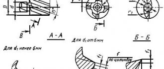
Drawing of parts from non-ferrous metals and alloys using local heating
The limiting values of the elongation coefficient can be reduced (to reduce the number of operations) by applying local heating of the outer annular flange of the workpiece with a width equal to , and at the same time cooling the central part with a diameter d0 (Fig. 199).
Crap. 199
1 - thermal insulation; 2 - tubular heater.
The optimal heating temperature of the workpiece flange when drawing parts from aluminum alloys and brass is given in table. 96.
Table 96
| Name and brand of material | Optimal temperature, °C |
| Aluminum alloys V95A-T1, D16A-T | 480-500 |
| Aluminum alloys D16A-M, AMtsA-M | 320-340 |
| Brass L62 | 450-480 |
The limit values of the elongation coefficient of cylindrical parts made of aluminum alloys and brass at the optimal temperature of local heating of the flange are given in table. 97.
Table 97
| Name and brand of material | Draw coefficient mpr | hpr/d* |
| Aluminum alloy AMgA-M | 0,39 | 1,44 |
| Aluminum alloy AMtsA-M | 0,42 | 1,18 |
| Aluminum alloy D16A-M | 0,37 | 1,62 |
| Aluminum alloy D16A-T | 0,33 | 2,10 |
| Aluminum alloy V95A-T1 | 0,32 | 2,20 |
| Brass L62 | 0,33 | 2,10 |
*hpr/d - the ratio of the maximum height of a cylindrical part to the diameter of the hood.
The limiting values of the elongation coefficient of square and rectangular hollow parts at the optimal temperature of local heating of the flange and the radii of curvature of the corner sections in the plan are given in Table. 98.
Table 98
| Name and brand of material | Radius of curvature of the corner section in plan rп, mm | Square hollow parts | Rectangular hollow parts | ||
| Draw coefficient m1pr | hpr/dу | Draw coefficient m1pr | hpr/dу | ||
| Aluminum alloy AMgA-M | 2,5 | 0,075 | 1,50 | 0,083 | 1,46 |
| Aluminum alloy AMtsA-M | 0,078 | 1,44 | 0,086 | 1,44 | |
| Aluminum alloy D16A-M | 0,072 | 1,58 | 0,079 | 1,51 | |
| Magnesium alloy MA1M | |||||
TEST METHODS
5.1. The quality of the surface of sheets and rolls is checked by external inspection without the use of magnifying devices.
5.2. To carry out tests, samples are cut from each selected sheet or roll in accordance with the requirements of the drawing and table. 2.
Scheme of cutting samples for testing ( b
- sheet width)
Table 2
| Sample number | Sample dimensions, mm | Test method | |
| width | length | ||
| 1,2 | 50 | 150 | On the adhesion strength of the zinc coating to the base metal |
| 3, 4, 5 | 50 | 50 | To determine the mass of zinc coating and thickness variations |
| 6 | 20 | 150 | To the bend |
| 7 | 90 | — | To draw out the spherical hole (x -test location) |
| 8 | 30 | 180-300 | Tensile |
| 9, 10 | 30 | 40 | Microstructure assessment |
Note
. Samples are cut with maximum size deviations of ± 3 mm.
5.3. To determine the mass of the zinc coating, the test sample is degreased, weighed, immersed in a solution of antimony oxide (Sb2O3) or antimony chloride (SbC13) in hydrochloric acid and kept until the violent gas evolution stops, then the sample is removed from the solution, thoroughly washed with cold and then hot water, dried with filter paper and weighed. Degreasing is carried out with synthetic technical ethyl alcohol.
A solution of antimony oxide or antimony chloride is prepared in the following way: 20 g of antimony oxide (or 32 g of antimony chloride) is dissolved in 1000 ml of concentrated hydrochloric acid (GOST 3118-77) for the second and first classes or 50 g of antimony oxides of class P.
Mass of zinc coating applied on both sides of the sheet, in grams ( m
) per 1 m2 is calculated using the formula
| (1) |
where is the mass of three samples (3, 4 and 5) before dissolution of the zinc coating, with an error of 0.01 g, g;
— mass of three samples (3, 4 and 5) after dissolution of the zinc coating, with an error of 0.01 g, g;
S
- actual surface area of the samples with an error of 1·10-6 m2, m2.
To determine the mass of zinc coating, it is allowed to use other methods that provide the necessary accuracy.
The method specified in this standard is used when there is disagreement in assessment.
(Changed edition, Amendment No. 1, 2).
5.4. The difference in thickness of the coating in the transverse direction of the sheet is determined as the absolute difference between the maximum and minimum values of the coating thickness on samples 3, 4 and 5 according to the formula
| (2) |
for which purpose, first calculate the thickness of the zinc coating on each of the samples using the formula
| (3) |
where is the coating thickness of the corresponding sample, µm;
— mass of the sample before removing zinc, g;
— mass of the sample after removal of zinc, g;
7.13—zinc density, g/cm3;
S
3 - surface area of the zinc coating, cm2.
(Changed edition, Amendment No. 1).
5.4.1. The average thickness and variation in thickness of the zinc coating on the surface of a sheet with a differentiated coating are determined and calculated for each side. To do this, after degreasing the sample, one side is covered with a dense layer of rubber glue or paraffin and zinc is removed from the opposite side, as indicated above. After re-weighing, the glue or paraffin is removed mechanically or in hot water. Removal of the zinc coating on the other side of the sample is carried out in the same way.
5.5. The bend test is carried out according to GOST 13813-68.
5.6. The spherical dimple drawing test is carried out according to GOST 10510-80. Make two measurements in the test area and determine the arithmetic mean.
5.7. The tensile test is carried out according to GOST 11701-84.
5.8. Determination of the grain size of ferrite is carried out according to GOST 5639-82 and structurally free cementite - according to GOST 5640-68.
5.9. Bending testing of galvanized steel up to 1 mm thick at an angle of 180° is carried out according to GOST 14019-80. A sample of galvanized steel is tested on a mandrel equal to the thickness of the rolled product.
Galvanized steel of the highest quality category must withstand 180° bending tests without mandrel until the sides touch.
By agreement between the consumer and the manufacturer, the bending test can be replaced by a double roof lock test in accordance with OST 1411-196-86, and for galvanized steel of the PK group, by testing on the U-1A device in accordance with GOST 4765-73.
Galvanized steel with a thickness of over 1.0 mm is tested at the request of the consumer according to a method agreed upon in the prescribed manner.
5.10. To control the quality of galvanized steel, it is allowed to use non-destructive control methods.