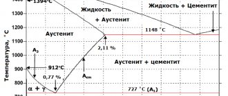
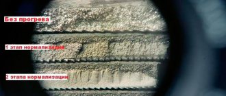
Hypereutectoid steels
Steels containing from 0.8 to 2% carbon are called hypereutectoid. The structure of hypereutectoid steel at room temperature consists of pearlite and secondary cementite, which can be located in the form of light grains or a light network located along the grain boundaries or in the form of needles (Fig. 3.5).
The amount of secondary cementite in the structure of hypereutectoid steel is small. It increases with increasing carbon concentration in it and ranges from 3.4% (at C = 1%) to 20.4% (at C = 2%) of the total mass of the alloy. Even its small content in the structure of hypereutectoid steel leads to a significant increase in its hardness and a decrease in ductility compared to eutectoid steel.
Secondary cementite in hypereutectoid steel occupies a small area, and it is difficult to determine it by eye, therefore the method used to determine the carbon content in hypoeutectoid steels is not used. However, the carbon content in hypereutectoid steels can be approximately determined. For example, let the thin section contain 90% perlite and 10% secondary cementite. Knowing that carbon is found in both pearlite and cementite, let’s create an equation for pearlite:
100% p – 0.8% C X1==0.72% C
90% p – X1
for cementite:
100% c – 6.67% C X2==0.67% C
10% c – X2
Hob. =X1 + X2= 0.72 + 0.67 = 1.39% C
Iron-carbon alloys containing more than 2% carbon are called cast iron.
Starting from this carbon concentration, eutectic appears in the structure of the alloys. Eutectics are characterized by increased brittleness and a relatively low crystallization temperature. Therefore, cast iron, unlike steel, is not subject to rolling, forging, stamping, and fills molds well in a liquid state.
Depending on the cooling rate and the content of impurities of subsequent processing, white, gray and malleable cast irons are obtained.
Steel structure
GENERAL CHARACTERISTICS OF STEEL
Steels are multicomponent alloys based on iron and carbon.
Iron and carbon are polymorphic chemical elements that are capable of changing the type of unit crystalline cell under the influence of temperature and pressure.
If carbon is the main alloying element in iron-based alloys, then such steels are called carbon steels. The carbon content in such steels does not exceed 2.14%. Steel that contains alloying elements (complicating its chemical composition) is called alloyed.
To assess the quality of steels, the patterns of destruction processes, develop new and improve existing technological processes, as well as when fighting defects and when working to improve product quality, it is necessary to know their structural state and its
influence on properties (operational, mechanical, technological, chemical, physical).
The structure of steels is a characteristic of properties. Structure-sensitive properties depend on heat treatment (hardness, strength). Stiffness characteristics (normal elastic modulus, shear modulus), heat resistance (scale resistance) are not sensitive to changes in structure.
Structure is understood as the structure, shape, size and nature of the arrangement of the corresponding phases. Phases are structural components that have a uniform (homogeneous) crystalline structure and state of aggregation, separated from other components by interfaces (boundaries). The components of microstructures are phases. A phase is understood as a homogeneous part of the alloy having
an interface, upon crossing which the composition and properties change abruptly. Steels can be single-phase, two-phase and multi-phase.
The structure of steels depends mainly on what chemical interactions the components (chemical elements that make up the steel) enter into. The components can form the following phases: liquid solutions, solid solutions, chemical compounds. In the solid state, steels may not have chemical interaction between the components, in which case the structure is a mechanical mixture,
consisting of two or more phases.
1.Types of component connections in steels
The conditions for the interaction of components in steels contribute to the formation of the following types of compounds:
1. Solid solutions in which the main component (solvent) retains its type of crystal lattice, and the atoms of the dissolved component replace part of the atoms in this lattice (substitutional solid solution) or are introduced into interstices (interstitial solid solution). On the iron-carbon phase diagram (see Appendix A), they correspond to areas bounded by decreasing and increasing lines
solubility. Solid solutions: austenite, ferrite.
Solid solution can be phase and structure.
2. A chemical compound has a new type of crystal lattice that is different from the crystal lattices of its constituent components. Therefore, like a chemically pure element, it melts at a constant temperature. It is formed with a strict stoichiometric ratio of chemical elements, i.e. it has the chemical formula - Fe3C (cementite) - this is a single-phase iron-based alloy containing 6.67% carbon (see Appendix A).
A chemical compound can be a phase and a structure. These are oxides (FeO), carbides (VC, WC, TiC), intermetallic compounds (FeAl).
3. A mechanical mixture of phases that do not dissolve in each other, each retaining its own type of unit cell (crystal lattice). Formation condition: strictly constant temperature and chemical composition of steel at critical points C (1147 °C, 4.3% C) and S (727 °C,
0.83% C) (see Appendix A).
A mechanical mixture always has a structure, since its composition may include two or more phases. At a temperature of 20 °C, perlite and ledeburite are a mechanical mixture of ferrite and cementite (see Appendix A).
The main phases and structures in iron-based alloys are given in Appendix B.
2. Carbon steels
The chemical composition of carbon steels is given in Appendix D.
A variety of carbon steels are usually classified according to various characteristics, given below.
By purpose:
- structural;
-instrumental.
By quality (the quality of steel increases with a decrease in the content of harmful impurities in it):
— ordinary quality (0.04% ≤ S ≤ 0.06%, 0.04% ≤ P ≤ 0.08%);
— qualitative (0.03% ≤ S ≤ 0.04%; 0.03% ≤ P ≤ 0.04%);
— high quality (S ≤ 0.03%; P ≤ 0.03%).
The quality of steel increases with a decrease in the content of harmful impurities of sulfur and phosphorus.
By % carbon content (C):
— low-carbon (up to 0.25% C);
- medium carbon (0.3 - 0.6% C);
— high-carbon (≥ 0.7% C).
According to the equilibrium microstructure and % carbon content at 20 °C:
- pearlite + ferrite (up to 0.83% C) - hypoeutectoid (Fig. 2);
- pearlite (= 0.83% C) - eutectoid (Fig. 3);
- pearlite + secondary cementite (more than 0.83% C) - hypereutectoid (Fig. 4).
Equilibrium state is achieved with slow cooling
steel products in a furnace, that is, after a heat treatment operation called annealing. The microstructure after all types of annealing of carbon steels corresponds to the iron-cementite diagram (see Appendix A). The microstructure of hypoeutectoid steel (in the annealed state) consists of light areas (grains) of ferrite and dark areas (grains) of pearlite (Fig. 2). In hypoeutectoid steels, almost all the carbon is contained in pearlite, so the type of structure can be used to roughly determine
steel grade using the formula
%С=0.83Х/100,
where X, % is the field of view of the microsection occupied by pearlite, in which
the condition for its formation is carbon content = 0.83%.
Rice. 2. A→P transformation: a – hypoeutectoid steel 20 (0.2% carbon).
Etchant: 3% nitric acid solution in alcohol. Processing: annealing. Hardness: 110 HB.
Base: Fe. Structural components: ferrite and pearlite;
b – schematic diagram of hypoeutectoid steel
The microstructure of eutectoid steel (in the annealed state) consists of alternating parallel plates of ferrite and cementite plates. The entire field of view (100%) is occupied by lamellar pearlite, with a carbon content in pearlite = 0.83% (Fig. 3).
Rice. 3. A→P transformation: a – eutectoid steel 80 (0.8% carbon).
Etchant: 3% nitric acid solution in alcohol. Processing: annealing. Hardness: 174 HB.
Base: Fe. Structural component: lamellar perlite (100%);
b – diagram of eutectoid steel
The microstructure of hypereutectoid steel in the annealed state is alternating parallel plates of ferrite and cementite on a dark background of pearlite and boundary precipitation of secondary cementite in the form of a continuous thin light network along the grain boundaries of former austenite, which has turned (during slow cooling with the furnace) into lamellar pearlite (Fig. 4) .
Rice. 4. A→P transformation: a – hypereutectoid steel U12 (1.2% carbon).
Etchant: 3% nitric acid solution in alcohol. Processing: annealing. Hardness: 190 HB.
Base: Fe. Structural components: lamellar perlite and cementite
secondary;
b – diagram of the image of hypereutectoid steel
The microstructure of steels depends on the shape of the phases and their location under
exposure to various operations of the technological process during the manufacture of products (Fig. 5 a, b).
Rice. 5. A→P transformation: a – eutectoid steel U8 (0.8% carbon).
Etchant: 3% nitric acid solution in alcohol. Treatment: cyclic annealing. The basis:
Fe. Structure granular perlite;
b – diagram of eutectoid steel
During cyclic annealing, recrystallization occurs in the temperature range no higher than 10–30 °C above the PSR line (727 °C) of the diagram
iron-cementite, so that lamellar pearlite does not turn out (see Appendix A). Tool steels should have a granular pearlite structure, since this ensures machinability, i.e.
It is possible to use high cutting speeds and achieve high cleanliness of the machined surface. The presence of a granular pearlite structure reduces the tendency of eutectoid and hypereutectoid steels to overheat during quenching.
Structure and phase composition of iron-carbon alloys
The structure and phase composition of alloys are studied using phase diagrams depicted in the “composition-temperature” coordinate axes. For two-component alloys, the composition axis is depicted as a segment, at the ends of which the component symbols (conventionally A and B) indicate. From point B to point A, the content of component A in the alloy increases from 0 to 100%, and the content of component B decreases to 0 from 100%. At any point on the axis, the sum of the concentrations of components A and B is equal to 100%. The composition characterized by the point / on the AB axis can be determined by the rule of segments, according to which the percentage of components is equal to the ratio of the lengths of the corresponding segments to the length of the axis multiplied by 100: A = (1B/AB)W; B = (A1/AB)J.
The state diagram shown in Fig. 6.3, characterizes an alloy, the components of which in the liquid state are unlimitedly soluble in each other, and in the solid state they form mechanical mixtures (they do not form solid solutions and chemical compounds).
Points tAm tB are the crystallization temperatures of free components A and B (the letters A and B also denote the crystals of these components in the alloy structure); E - eutectic - a special structure, which is a mechanical mixture of simultaneously crystallized from a liquid and therefore very small and closely mixed crystals of components A and B, the content of which is proportional to the segments EV and A3, respectively; e is the eutectic point, indicating the composition of the eutectic and its crystallization temperature, the beginning and end of which, unlike other compositions, coincide.
The eutectic is not a phase, but a structural component (an element of the alloy structure), therefore its 100% content, unlike the components, is marked on the diagram with a dashed line.
The tAetB curve is the temperature curve of the onset of crystallization of the alloy, or the curve of the upper critical points, called liquidus (from the Latin liquidus - liquid). Above the liquidus, the alloy is in a molten state (P - melt). The ced line is the line of temperatures at the end of crystallization of the alloy, or the line of lower critical points, called solidus (from the Latin solidus - solid). Below the solidus, the alloy consists of solid crystals (A, B and E). Between liquidus and solidus, liquid (P) and solid (A and B) phases exist simultaneously.
The temperatures of the beginning and end of crystallization of the alloy / correspond to points a, and b, of the alloy - to points a and b„.
Let us draw a horizontal line through point 2 to the boundaries of the tAec region. This line is the axis of phase compositions, at the ends of which we have: on the left - 100% of component A, and on the right (at the boundary with the melt) - 100% of the melt. This is marked with the letters A + P. In this region, crystals of component A are released from the melt upon cooling. In the region etBd, B + P is written, since here component B is released from the melt in the solid state. Point 2 divides the axis of phase compositions A - P into segments A2 and P2, by measuring which, it is possible to determine the percentages of phases A and P in the alloy / at temperature at point 2.
The nature of the change in the phase composition of the alloy with decreasing temperature can be traced by plotting the axes of the phase compositions for various points on the vertical. A comparison of the segments at points ah 2 and b/ shows that as the temperature decreases from point H/ to point b [, the content of component A increases from 0 (Aa = 0) to [Ab/(Ab + Pfc)]100 ~ 44%, and the melt content decreases from 100% to [Pb/(Ab + Pd)]100 = 56%. At points 4,i3 we have: Pb = E3 and Ab - Ab, i.e. the amount of component A that was released from the melt while it remained liquid now exists in the solid alloy, and the melt, which at the end of crystallization (at point b) makes up about 56% of the alloy, turns into eutectic. Accordingly, in the areas AcE and 3edB A + E and B + E are indicated.
Let us monitor the change in the composition of the melt in the alloy during cooling. At temperature t4 (point 4) and below, down to point a and, the alloy is completely liquid, therefore the composition of the melt and the composition of the alloy are the same (point h on the composition axis). At point ai, crystallization of the melt begins and the first crystals of component B are released from it. As a result of the partial loss of this component, the composition and quantity of the melt changes. To determine the composition of the melt at temperature ts, from point 5, draw a horizontal straight line to the boundary with the melt and drop a perpendicular to the composition axis at the point. At a lower temperature f6, the composition of the melt will be characterized by point g, and at the end of crystallization (at point b) it will correspond to the composition of the eutectic. Consequently, when the alloy is cooled, the content of components A and B in the liquid phase (melt composition) changes along the ape curve. Similarly, along the ap curve, the composition of the melt changes during crystallization of the alloy.
Let us consider how the structures of an alloy are formed depending on its composition. Let us roughly represent the crystals of component A as triangles, and those of component B as squares; then the structure of the eutectic will be represented by a mixture of triangles and squares, only very small ones, practically indistinguishable against the background of large crystals of pure components. The areas occupied in the eutectic by triangles (component A) and squares (component B) are 57.5 and 42.5%, respectively, which corresponds to the segments E and AE of the composition axis. In order to determine the structure of the alloy /, we measure the lengths of the segments E3 and A} and from them we calculate the percentage of component A and eutectic in the alloy. We get 44 and 56%. Consequently, the area occupied by large triangles in the picture of the structure of the alloy / should be 44% of the total area, and the remaining area should be the eutectic represented by the dots. In a similar way, by measuring the segments E/g and hB (taking into account the fact that large crystals in this case are squares), we obtain the structure of the alloy.
To solve the inverse problem—determining the composition of an alloy based on its structure—you need to measure the areas occupied by the elements of the structure and use a diagram to determine the composition of the alloy.
Structure of pure iron. Pure iron, when cooled or heated, undergoes a series of transformations in the solid state, which give critical points on the cooling curve (Fig. 6.4). In the intervals between these points, iron exists in the form of four modifications (a-, p~, y- and 8-Fe), of which y-Fe has a face-centered cubic (fcc) crystal lattice with a parameter of 3.6 A, and the rest have a body-centered crystal lattice cubic (bcc) with a parameter of 2.8 A. Often p-Fe and 8-Fe are not isolated separately and are considered as an a-modification. The transition y -> a (911 °C) upon cooling or oc -> y upon heating plays a major role in the formation of the properties of steel.
Phases in the structure of steel. Carbon and iron, depending on temperature, form a liquid solution (melt P), two solid solutions - ferrite (F) and austenite (A) - and a chemical compound Fe3C called cementite (C).
Ferrite is a solid solution of carbon in a-iron, existing at temperatures below 911 °C. The solubility of carbon in a-iron is low (no more than 0.02%), since carbon can only be present in the dense lattice of a-iron by replacing iron atoms, which requires high energy.
Austenite is a solid solution of carbon in y-iron, existing at temperatures above 727 0C. Below 727 0C, austenite decomposes into ferrite and cementite. In y-iron, carbon dissolves up to 2.14%. In this case, carbon is inserted between the iron atoms due to the fact that the y-lattice is not so tightly packed.
Carbon steel structure. The structure of carbon steel at normal temperature is formed by two phases (two types of crystals): very soft and ductile ferrite and very hard and brittle cementite. The more carbon in steel, the more cementite and less ferrite is formed, and the higher the hardness and lower the ductility of the steel. With a carbon content of less than 0.01%, steel consists of ferrite only.
If the steel contains 0.8% carbon, then its structure is a eutectoid (eutectic-like) mixture of small crystals of ferrite (88%) and cementite (12%), called pearlite (P). At 200x magnification, the ferrite and cementite crystals in pearlite are practically indistinguishable, while the ferrite crystals that previously separated from austenite are quite large. The structure of pearlite is visible only at high magnification. With a carbon content of less than 0.8%, the steel structure includes pearlite and ferrite; with a carbon content of more than 0.8%, pearlite and cementite.
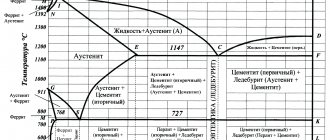
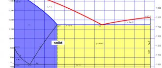
State diagram of iron-carbon alloys. The Fe - Fe3C phase diagram is only part of the complete Fe - C diagram, so carbon is not present as a phase in the diagram. In this part of the diagram, cementite, which is one of the phases, plays the role of the second component, although it is not one (the second component is carbon). The first component, iron, also does not appear in the diagram, since it always dissolves some amount of carbon and is a solid solution (ferrite or austenite).
ACD curve - liquidus. Above the liquidus is the melt region (P). BECF-solidus curve. Below the solidus, all alloys are hard. In the BESG region, this is a solid solution of austenite, and in the ECFKS region, it is a mechanical mixture of austenite and cementite with a eutectic called ledeburite (L). An alloy (cast iron) with a carbon content of 4.3% consists entirely of eutectic. It has the lowest melting point (crystallization) - 1,147 ° C (point C). At / > 121 °C, ledeburite is a mechanical mixture of small crystals of austenite and cementite, and at t < 727 °C - pearlite and cementite.
The fact is that a solid solution (austenite) decomposes upon cooling in the same way as a liquid solution (melt) with the release of certain dissolved substances. Therefore, the intersections of the diagram lines at points S and C are similar to each other. Point S is called a eutectoid point, i.e. similar to the eutectic point C. The structure formed at point S is pearlite. The GSE curve is the temperature curve for the onset of austenite decomposition. In the GS region (in the GSP region), ferrite precipitates from austenite, and in the SE region (in the SEFK region), cementite (secondary) precipitates. PSK line is the temperature line of the end of austenite decomposition, or the line of eutectoid transformations. Below this line, austenite does not exist. It turns into perlite.
Let us consider the processes during heating of hypoeutectoid steel containing 0.4% carbon (point 1). Until the temperature reaches 727 °C (PS line), the steel will consist of ferrite and pearlite (F + P). At a temperature of 727 °C (point 2), pearlite (P) transforms into austenite (A), since oc-iron transforms into y-iron. In ferrite (F), the a-modification of iron is preserved and it remains in the steel. When the temperature rises above 727 °C, the amount of ferrite decreases and it dissolves in austenite. At point 3, the ferrite content will be 0% and the austenite content will be 100%.
Steel, unlike cast iron, completely transforms into the austenite phase when heated. Further heating causes the steel to melt. The first drops of melt will appear at the temperature at point 4. Then the amount of melt will increase, and the amount of austenite will decrease until it completely dissolves in the melt (at point 5).
When the alloy cools, everything will happen in the reverse order. With very slow (equilibrium) cooling, the initial steel structure is formed, consisting of ferrite and pearlite. This structure is called equilibrium. With rapid cooling, nonequilibrium (metastable) structures characterized by high hardness arise. This is what steel hardening is based on.
Let us consider the processes occurring during cooling of hypereutectoid steel with a carbon content of 1.2%. At the temperature at point 8, crystallization of the melt begins; Austenite crystals are released from it. As the temperature decreases, the solid phase (austenite) becomes more and more, and the liquid phase becomes less and less. At point 9 the transition of the melt to austenite ends. The alloy exists in the form of austenite up to point 10. Starting from this temperature, austenite decomposes and cementite is released from it. This cementite is called secondary (C2) to distinguish it from cementite (C), which precipitates in the CDF region from the melt and has no restrictions on the growth and arrangement of crystals. Secondary cementite is released in extremely cramped conditions, so its crystals are very small and are located in the form of narrow layers along the boundaries of austenite crystals. The release of secondary cementite ends at point //. The amount of released secondary cementite in our alloy is 6.8%. The austenite remaining at the end of decomposition (93.2%) at a temperature of 727 °C transforms into pearlite, i.e. disintegrates into a mixture of small crystals of ferrite and cementite.
The structure and phase composition of alloys are studied using phase diagrams depicted in the “composition-temperature” coordinate axes. For two-component alloys, the composition axis is depicted as a segment, at the ends of which the component symbols (conventionally A and B) indicate. From point B to point A, the content of component A in the alloy increases from 0 to 100%, and the content of component B decreases to 0 from 100%. At any point on the axis, the sum of the concentrations of components A and B is equal to 100%. The composition characterized by the point / on the AB axis can be determined by the rule of segments, according to which the percentage of components is equal to the ratio of the lengths of the corresponding segments to the length of the axis multiplied by 100: A = (1B/AB)W; B = (A1/AB)J.
The state diagram shown in Fig. 6.3, characterizes an alloy, the components of which in the liquid state are unlimitedly soluble in each other, and in the solid state they form mechanical mixtures (they do not form solid solutions and chemical compounds).
Points tAm tB are the crystallization temperatures of free components A and B (the letters A and B also denote the crystals of these components in the alloy structure); E - eutectic - a special structure, which is a mechanical mixture of simultaneously crystallized from a liquid and therefore very small and closely mixed crystals of components A and B, the content of which is proportional to the segments EV and A3, respectively; e is the eutectic point, indicating the composition of the eutectic and its crystallization temperature, the beginning and end of which, unlike other compositions, coincide.
The eutectic is not a phase, but a structural component (an element of the alloy structure), therefore its 100% content, unlike the components, is marked on the diagram with a dashed line.
The tAetB curve is the temperature curve of the onset of crystallization of the alloy, or the curve of the upper critical points, called liquidus (from the Latin liquidus - liquid). Above the liquidus, the alloy is in a molten state (P - melt). The ced line is the line of temperatures at the end of crystallization of the alloy, or the line of lower critical points, called solidus (from the Latin solidus - solid). Below the solidus, the alloy consists of solid crystals (A, B and E). Between liquidus and solidus, liquid (P) and solid (A and B) phases exist simultaneously.
The temperatures of the beginning and end of crystallization of the alloy / correspond to points a, and b, of the alloy - to points a and b„.
Let us draw a horizontal line through point 2 to the boundaries of the tAec region. This line is the axis of phase compositions, at the ends of which we have: on the left - 100% of component A, and on the right (at the boundary with the melt) - 100% of the melt. This is marked with the letters A + P. In this region, crystals of component A are released from the melt upon cooling. In the region etBd, B + P is written, since here component B is released from the melt in the solid state. Point 2 divides the axis of phase compositions A - P into segments A2 and P2, by measuring which, it is possible to determine the percentages of phases A and P in the alloy / at temperature at point 2.
The nature of the change in the phase composition of the alloy with decreasing temperature can be traced by plotting the axes of the phase compositions for various points on the vertical. A comparison of the segments at points ah 2 and b/ shows that as the temperature decreases from point H/ to point b [, the content of component A increases from 0 (Aa = 0) to [Ab/(Ab + Pfc)]100 ~ 44%, and the melt content decreases from 100% to [Pb/(Ab + Pd)]100 = 56%. At points 4,i3 we have: Pb = E3 and Ab - Ab, i.e. the amount of component A that was released from the melt while it remained liquid now exists in the solid alloy, and the melt, which at the end of crystallization (at point b) makes up about 56% of the alloy, turns into eutectic. Accordingly, in the areas AcE and 3edB A + E and B + E are indicated.
Let us monitor the change in the composition of the melt in the alloy during cooling. At temperature t4 (point 4) and below, down to point a and, the alloy is completely liquid, therefore the composition of the melt and the composition of the alloy are the same (point h on the composition axis). At point ai, crystallization of the melt begins and the first crystals of component B are released from it. As a result of the partial loss of this component, the composition and quantity of the melt changes. To determine the composition of the melt at temperature ts, from point 5, draw a horizontal straight line to the boundary with the melt and drop a perpendicular to the composition axis at the point. At a lower temperature f6, the composition of the melt will be characterized by point g, and at the end of crystallization (at point b) it will correspond to the composition of the eutectic. Consequently, when the alloy is cooled, the content of components A and B in the liquid phase (melt composition) changes along the ape curve. Similarly, along the ap curve, the composition of the melt changes during crystallization of the alloy.
Let us consider how the structures of an alloy are formed depending on its composition. Let us roughly represent the crystals of component A as triangles, and those of component B as squares; then the structure of the eutectic will be represented by a mixture of triangles and squares, only very small ones, practically indistinguishable against the background of large crystals of pure components. The areas occupied in the eutectic by triangles (component A) and squares (component B) are 57.5 and 42.5%, respectively, which corresponds to the segments E and AE of the composition axis. In order to determine the structure of the alloy /, we measure the lengths of the segments E3 and A} and from them we calculate the percentage of component A and eutectic in the alloy. We get 44 and 56%. Consequently, the area occupied by large triangles in the picture of the structure of the alloy / should be 44% of the total area, and the remaining area should be the eutectic represented by the dots. In a similar way, by measuring the segments E/g and hB (taking into account the fact that large crystals in this case are squares), we obtain the structure of the alloy.
To solve the inverse problem—determining the composition of an alloy based on its structure—you need to measure the areas occupied by the elements of the structure and use a diagram to determine the composition of the alloy.
Structure of pure iron. Pure iron, when cooled or heated, undergoes a series of transformations in the solid state, which give critical points on the cooling curve (Fig. 6.4). In the intervals between these points, iron exists in the form of four modifications (a-, p~, y- and 8-Fe), of which y-Fe has a face-centered cubic (fcc) crystal lattice with a parameter of 3.6 A, and the rest have a body-centered crystal lattice cubic (bcc) with a parameter of 2.8 A. Often p-Fe and 8-Fe are not isolated separately and are considered as an a-modification. The transition y -> a (911 °C) upon cooling or oc -> y upon heating plays a major role in the formation of the properties of steel.
Phases in the structure of steel. Carbon and iron, depending on temperature, form a liquid solution (melt P), two solid solutions - ferrite (F) and austenite (A) - and a chemical compound Fe3C called cementite (C).
Ferrite is a solid solution of carbon in a-iron, existing at temperatures below 911 °C. The solubility of carbon in a-iron is low (no more than 0.02%), since carbon can only be present in the dense lattice of a-iron by replacing iron atoms, which requires high energy.
Austenite is a solid solution of carbon in y-iron, existing at temperatures above 727 0C. Below 727 0C, austenite decomposes into ferrite and cementite. In y-iron, carbon dissolves up to 2.14%. In this case, carbon is inserted between the iron atoms due to the fact that the y-lattice is not so tightly packed.
Carbon steel structure. The structure of carbon steel at normal temperature is formed by two phases (two types of crystals): very soft and ductile ferrite and very hard and brittle cementite. The more carbon in steel, the more cementite and less ferrite is formed, and the higher the hardness and lower the ductility of the steel. With a carbon content of less than 0.01%, steel consists of ferrite only.
If the steel contains 0.8% carbon, then its structure is a eutectoid (eutectic-like) mixture of small crystals of ferrite (88%) and cementite (12%), called pearlite (P). At 200x magnification, the ferrite and cementite crystals in pearlite are practically indistinguishable, while the ferrite crystals that previously separated from austenite are quite large. The structure of pearlite is visible only at high magnification. With a carbon content of less than 0.8%, the steel structure includes pearlite and ferrite; with a carbon content of more than 0.8%, pearlite and cementite.
State diagram of iron-carbon alloys. The Fe - Fe3C phase diagram is only part of the complete Fe - C diagram, so carbon is not present as a phase in the diagram. In this part of the diagram, cementite, which is one of the phases, plays the role of the second component, although it is not one (the second component is carbon). The first component, iron, also does not appear in the diagram, since it always dissolves some amount of carbon and is a solid solution (ferrite or austenite).
ACD curve - liquidus. Above the liquidus is the melt region (P). BECF-solidus curve. Below the solidus, all alloys are hard. In the BESG region, this is a solid solution of austenite, and in the ECFKS region, it is a mechanical mixture of austenite and cementite with a eutectic called ledeburite (L). An alloy (cast iron) with a carbon content of 4.3% consists entirely of eutectic. It has the lowest melting point (crystallization) - 1,147 ° C (point C). At / > 121 °C, ledeburite is a mechanical mixture of small crystals of austenite and cementite, and at t < 727 °C - pearlite and cementite.
The fact is that a solid solution (austenite) decomposes upon cooling in the same way as a liquid solution (melt) with the release of certain dissolved substances. Therefore, the intersections of the diagram lines at points S and C are similar to each other. Point S is called a eutectoid point, i.e. similar to the eutectic point C. The structure formed at point S is pearlite. The GSE curve is the temperature curve for the onset of austenite decomposition. In the GS region (in the GSP region), ferrite precipitates from austenite, and in the SE region (in the SEFK region), cementite (secondary) precipitates. PSK line is the temperature line of the end of austenite decomposition, or the line of eutectoid transformations. Below this line, austenite does not exist. It turns into perlite.
Let us consider the processes during heating of hypoeutectoid steel containing 0.4% carbon (point 1). Until the temperature reaches 727 °C (PS line), the steel will consist of ferrite and pearlite (F + P). At a temperature of 727 °C (point 2), pearlite (P) transforms into austenite (A), since oc-iron transforms into y-iron. In ferrite (F), the a-modification of iron is preserved and it remains in the steel. When the temperature rises above 727 °C, the amount of ferrite decreases and it dissolves in austenite. At point 3, the ferrite content will be 0% and the austenite content will be 100%.
Steel, unlike cast iron, completely transforms into the austenite phase when heated. Further heating causes the steel to melt. The first drops of melt will appear at the temperature at point 4. Then the amount of melt will increase, and the amount of austenite will decrease until it completely dissolves in the melt (at point 5).
When the alloy cools, everything will happen in the reverse order. With very slow (equilibrium) cooling, the initial steel structure is formed, consisting of ferrite and pearlite. This structure is called equilibrium. With rapid cooling, nonequilibrium (metastable) structures characterized by high hardness arise. This is what steel hardening is based on.
Let us consider the processes occurring during cooling of hypereutectoid steel with a carbon content of 1.2%. At the temperature at point 8, crystallization of the melt begins; Austenite crystals are released from it. As the temperature decreases, the solid phase (austenite) becomes more and more, and the liquid phase becomes less and less. At point 9 the transition of the melt to austenite ends. The alloy exists in the form of austenite up to point 10. Starting from this temperature, austenite decomposes and cementite is released from it. This cementite is called secondary (C2) to distinguish it from cementite (C), which precipitates in the CDF region from the melt and has no restrictions on the growth and arrangement of crystals. Secondary cementite is released in extremely cramped conditions, so its crystals are very small and are located in the form of narrow layers along the boundaries of austenite crystals. The release of secondary cementite ends at point //. The amount of released secondary cementite in our alloy is 6.8%. The austenite remaining at the end of decomposition (93.2%) at a temperature of 727 °C transforms into pearlite, i.e. disintegrates into a mixture of small crystals of ferrite and cementite.
Carbon steel in equilibrium
Goal of the work:
— study of the state diagram of iron-carbon alloys;
— analysis of transformations occurring in alloys during cooling and heating;
— determination of the phase and structural state of alloys depending on their composition and temperature;
— establishing the relationship between the structure and properties of steel.
By equilibrium we mean a state in which all phase transformations in the alloy are completely completed in accordance with the state diagram. This occurs only at very low cooling (heating) rates. The equilibrium state corresponds to the minimum value of free energy and does not undergo spontaneous changes in time. That's why it is called stable.
Transformations occurring in steels in an equilibrium state are described by the “ iron-cementite ” presented in Figure 8.1.
Figure 8.1 – Iron -cementite diagram
The following solid phases may be present in iron-carbon alloys: ferrite, austenite, cementite.
Ferrite is a solid solution of interstitial carbon in a-iron, which has a body-centered cubic lattice. In the iron-cementite diagram, there are two regions of ferrite - the high-temperature region ANN and the low-temperature region GPQ. The maximum solubility in the high-temperature region is 0.10% - point H, in the low-temperature region 0.02% - point P. The carbon content at room temperature is 0.01%. Ferrite is soft and plastic (sB = 200 – 300 MPa, d = 20–50%, 80 – 100 HB).
Austenite is a solid solution of interstitial carbon in g-iron, which has a face-centered cubic lattice. iron -cementite diagram, austenite occupies the NJESG region. The maximum solubility of carbon in austenite is 2.14% - point E. In terms of mechanical properties, austenite is close to ferrite. Hot pressure treatment is carried out in the region where austenite exists (a single-phase solid solution is characterized by high plasticity).
Cementite is a chemical compound of iron and carbon - iron carbide, the chemical formula of which is Fe3C. The carbon content in cementite is 6.67%. Cementite has high hardness (» 800 HV) and brittleness. It has a complex rhombic lattice. It consists of a number of octahedra, the axes of which are located at certain angles to each other.
Crystallization of alloys whose carbon content is less than 0.5% (point B) begins with the separation of ferrite crystals from a liquid solution. When the carbon content is more than 0.5%, steels crystallize with the precipitation of austenite.
Alloys containing carbon from 0.1% (point H) to 0.5% (point B) undergo a peritectic transformation , which consists in the fact that a liquid solution having at this temperature a concentration corresponding point B (0.5% C), interacting with the ferrite crystals released from it with a concentration of point H (0.1% C), forms a new phase - austenite crystals with a concentration of point J (0.16% C):
FN + ZHV ® AJ.
With a further decrease in temperature in alloys with a carbon content from 0.1 to 0.16%, the ferrite remaining after the peritectic transformation recrystallizes into austenite. In steels with a carbon content greater than 0.16%, the remaining liquid solidifies to form austenite. Below the NJ and JE lines, the alloys have a uniform austenitic structure.
All alloys with a carbon content of more than 0.02% (point P) at a temperature of 727 oC (PSK line) undergo a eutectoid transformation . During the eutectoid transformation, austenite, which at this temperature has a carbon concentration corresponding to point S (0.8% C), decomposes to form a eutectoid mixture - pearlite (ferrite of the composition of point P (0.02% C) and cementite):
AS ® FR + C.
The eutectoid mixture of ferrite and cementite formed as a result of the eutectoid decomposition of austenite is called pearlite.
In alloys with a carbon content of less than 0.8% (point S), the eutectoid transformation is preceded by the precipitation of ferrite from austenite, which occurs in the temperature range limited by the GS and PS lines. In this case, in the remaining austenite, the carbon concentration changes along the GS line. In alloys with a carbon content of more than 0.8% (point S), the eutectoid transformation is preceded by the separation of cementite from austenite. The precipitation of cementite occurs in the temperature range limited by the ES and SK lines. In this case, the carbon concentration in the remaining austenite changes along the ES line.
Iron-carbon alloys, depending on the carbon content, are divided into three groups: technical iron, steel, and cast iron.
Technical iron is alloys with a carbon content of less than 0.02% (point P). As follows from the “ iron-cementite ” , commercial iron has the structure of ferrite or ferrite and tertiary cementite, which in the form of separate small inclusions is located along the boundaries of ferrite grains (Figure 8.2, a). Tertiary cementite is released from ferrite as a result of a decrease in carbon solubility when the temperature decreases from eutectoid (727 °C) to room temperature. The limiting solubility of carbon in ferrite is limited by the GPQ line. The properties of industrial iron are similar to ferrite.
Steels are alloys with a carbon content from 0.02% (point P) to 2.14% (point E). In the structure of steel, as the carbon content increases, the proportion of cementite increases and, accordingly, the proportion of ferrite decreases. This leads to an increase in the hardness and strength of steel and a decrease in its ductility, a change in physical and technological properties. Depending on the carbon content, steels are divided according to their structure into hypoeutectoid, eutectoid and hypereutectoid .
Hypoeutectoid steels contain from 0.02% carbon (point P) to 0.8% carbon (point S). It has the structure of ferrite (light grains) and pearlite (dark grains) (Figure 8.2, b, c). The quantitative ratio between pearlite and ferrite depends on the carbon content. As the carbon content increases, the perlite content increases in direct proportion. When the carbon concentration in steel is 0.8%, the amount of pearlite is 100%. Knowing the area occupied by pearlite, it is possible to determine the carbon content in carbon steel with sufficient accuracy for practice:
C = ,
where A is the area occupied by perlite.
Eutectoid steel contains 0.8% carbon (point S) and consists of pearlite (Figure 8.2, d).
Figure 8.2 – Microstructure of technical iron (a), hypoeutectoid steels with a carbon content of 0.20% (b) and 0.45% (c), eutectoid (d) and hypereutectoid (e) steels
Hypereutectoid steel contains from 0.8% carbon (point S) to 2.14% carbon (point E). Hypereutectoid steel consists of pearlite and cementite (Figure 8.2, e).
Thus, the structure, and therefore the properties of steel, are determined by the amount of carbon in it. Hypoeutectoid steels, containing up to 0.8% carbon, are structural , intended for the manufacture of machine parts (engineering steels), structures and structures (construction steels). To a large extent, the properties of carbon steels, and, consequently, their scope of application depend on the content of harmful impurities of sulfur and phosphorus in them. The less of them in steel, the higher its quality.
Ordinary quality steels , the cheapest, are general-purpose structural steels and contain up to 0.07% phosphorus, 0.06% sulfur, 0.06–0.49% carbon. According to the guaranteed properties, they are divided into three groups - A, B, C. In steels of group A - mechanical properties are guaranteed, group B - chemical composition; In group B steels, mechanical properties and chemical composition are guaranteed.
Group A steel is marked with the letters St and the number 0, 1, 2, ... 6, for example, St1. In steels of group B, the letter B is placed before the letters St, for example, BSt2. In group B steels, the letters St are preceded by the letter B, for example, VSt3. As the reference number increases, the carbon content in steel increases, which leads to an increase in strength properties and a decrease in ductility and weldability.
Group A steels are used for the production of rolled products (channels, angles, sheets, rods, pipes, etc.) used for riveted and bolted structures, as well as for lightly loaded machine parts (shafts, axles, gears, bolts, etc.) not subject to heating during processing. Group B steels are used for the manufacture of products subject to heating (hot forming, welding, heat treatment). Group B steels are used for the manufacture of welded structures subjected to strength calculations.
At the end of the steel grade the letters “ kp ” , “ ps ” , “ sp ” . The letters “ kp ” indicate that the steel is boiling, “ ps ” is semi-calm, and “ sp ” is calm.
High-quality structural steel contains half as much sulfur and phosphorus as compared to general-purpose steel and has higher mechanical properties. It is marked with numbers, for example, 08, 10, ... 80, showing the carbon content in hundredths of a percent.
Low-carbon steels, containing up to 0.25% carbon, have low strength and high ductility and are used for the manufacture of products by sheet cold stamping (05 kp...10), as well as for parts strengthened by carburization, and for various welded joints (Steel 15, Steel 20). In addition, bolts, studs, nuts, rollers for non-critical purposes, etc. are made from the latest steels.
Medium carbon steel grades 30-50 are intended for critical high-strength parts with a viscous core (gears, connecting rods, crankshafts, camshafts, screws, axles, bushings, levers, etc.). As a rule, parts made from these steels are subjected to improvement (a type of heat treatment).
High-carbon steels 55-85 are used for springs, leaf springs, as well as high-strength parts: rolling rolls (steel 60), crane wheels (steel 75), clutch discs (steel 85), etc. Parts made from these steels are subjected to hardening and tempering ( types of heat treatment).
For the manufacture of various tools, carbon tool steel is used, containing carbon from 0.7 to 1.3%. It has a reduced content of harmful impurities: phosphorus - up to 0.035% and sulfur - up to 0.03% (high-quality steel) or phosphorus - up to 0.03% and sulfur - up to 0.02% (high-quality steel). This steel is produced in the following grades: U7 - U13 (high-quality) or U7A - U13A (high-quality). Here “U” means “carbon tool steel”, the number after “U” is the carbon content in tenths of a percent (for example, U12 contains 1.2% carbon). The letter “A” at the end of the brand means high-quality steel.
Steel grades U7 and U8 are tougher than others, since they do not have cementite in their structure, and they are used for the manufacture of impact tools - hammers, chisels, axes, punches, chisels, chisels, stamps, etc.
Steels U10 and U11 have slightly lower viscosity and slightly higher hardness (since their structure contains a small amount of cementite) and are used for the manufacture of cutters, drills, taps, and lathes.
Steels U12 and U13 have low toughness and high hardness and are used for the manufacture of tools that do not experience shock loads (files, razors, rasps, etc.).
Control questions
1. Describe the transformations that occur in steels during heating or cooling, indicate their temperatures.
2. Define the phases present in steels and indicate the carbon content in them.
3. Give a classification of carbon steels by quality, carbon content and purpose.
4. Study the markings of steels and indicate the areas of application of the listed steels:
St2, BSt3, VSt4, St6;
08 kp, 10, 15, 20, 25, 30, 40, 50, 60, 75, 80;
U7, U8, U10A, U11, U12, U13.
Materials Science
Study of the microstructure and properties of carbon steels
Target:
study transformations in alloys of the iron-cementite system and the structure of steels of various compositions in an equilibrium state.
Determine the carbon content in the steels under study and their grades. The microstructure of steels is studied in an equilibrium state, that is, in a state when the processes of phase transformations have completely occurred, which is achieved only with very slow cooling. The structural components of iron-carbon alloys in the equilibrium state are determined from the iron-cementite phase diagram. A special feature of the diagram is the presence on the composition axis of two scales showing the content of carbon and cementite (Fig. 1). Iron-carbon alloys containing less than 2.14% carbon are called steels, and more than 2.14% are called cast iron. The structure of steel in an equilibrium state depends on the carbon content in it. After complete annealing, carbon steel contains the following phases and structural components: ferrite, cementite, pearlite. Ferrite (F)
is a solid solution of carbon in α-iron.
It is a product of the diffusion transformation of austenite when it is cooled below GPSK
(see Fig. 1).
Under a microscope, ferrite is observed in the form of light grains of unequal brightness (Fig. 2). The latter is explained by unequal etching due to the anisotropy of the properties of ferrite. The solubility of carbon in ferrite changes with temperature, which is reflected in the phase diagram (Fig. 1) - line GPQ
.
The maximum carbon content in ferrite at room temperature reaches 0.006%. Ferrite is a plastic phase. Its relative elongation δ=50% and hardness depends on the concentration of carbon and other dissolved impurities and varies within HB 450÷800. Ferrite has ferromagnetic properties and becomes paramagnetic at a temperature of 768°C. Cementite (C)
is a chemical compound of carbon with iron - iron carbide Fe3C. The crystal lattice of cementite is complex orthorhombic. Cementite has a metallic luster, thermal and electrical conductivity, and low magnetic properties up to a temperature of 210°C. The melting point of cementite at atmospheric pressure has not been established, since it is an unstable chemical compound and decomposes into iron and carbon at high temperatures. Depending on the cooling conditions of austenite, cementite can have a granular or lamellar form. A cementite network of plates covering pearlite grains in the structure of hypereutectoid steel reduces its ductility and strength and increases its hardness. Cementite is the hardest component, HB 8000. Its ductility is practically zero. Therefore, with an increase in the amount of cementite in steel and an increase in the concentration of carbon in it, the hardness of the steel increases, and the ductility decreases.
Rice. 1 – Diagram of the state of alloys of the iron-carbon system
Perlite (P)
- a eutectoid mixture of cementite and ferrite crystals, formed during the diffusion decomposition of austenite as a result of slow cooling of the latter.
The carbon content in perlite is 0.8% (point S
, Fig. 1). When making a thin section, plates of cementite, which are harder than ferrite, are ground less and therefore protrude from the rest of the perlite mass. Ferrite, as a soft component, is ground off more, which increases during etching. Therefore, under oblique lighting, perlite is visible under a microscope in the form of dark and light stripes. Depending on the form of cementite, they distinguish: a) granular pearlite, in which cementite has the form of grains located in ferrite (Fig. 3. a); b) lamellar pearlite, in which cementite and ferrite are in the form of plates; the latter form a mixture of alternating layers of cementite (Fig. 3, b) and ferrite. The shape and size of cementite particles in pearlite significantly affect the properties of steel. For example, granular pearlite is more plastic and has lower hardness than lamellar pearlite. As the size of cementite particles decreases, the hardness and strength of pearlite increase.
Fig. 2 - Scheme of sketching the structure of ferrite (commercial iron)
Fig. 3 - Scheme of sketching the structure of perlite a - granular perlite; b - lamellar pearlite (eutectoid steel)
Ordinary lamellar pearlite has a tensile strength σb=820 MPa and relative elongation δ5=15%, and coarse lamellar pearlite σb=550 MPa and δ5=5%. Granular perlite has σb=630 MPa and δ5=20%. The hardness of lamellar perlite is HB 2000÷2500, and that of granular pearlite is HB 1600÷2200. On a microsection in a conventional optical microscope at low magnification (up to 200x), pearlite is observed in the form of dark grains in which neither plates nor cementite grains are visible, since the size of cementite particles is very small.
The structure of steel in an equilibrium state depends on the carbon content in it. Technical iron contains no more than 0.02% carbon and can be a two-phase or single-phase alloy. Technically pure iron is called Armco iron. It is produced in large quantities industrially with a total impurity content of about 0.15%. Alloys with a carbon content of up to 0.006% consist of ferrite, and in the concentration range of 0.006-0.02% - of ferrite and tertiary cementite, which is released along the boundaries of ferrite grains due to changes in the solubility of carbon in ferrite with decreasing temperature (see Fig. 1) . Hypoeutectoid steels contain from 0.02 to 0.8% carbon. Steels consist of ferrite (light grains) and pearlite (dark grains) (Fig. 3, a). The amount of pearlite increases and ferrite decreases in proportion to the increase in carbon content. Based on the ratio of areas occupied in the structure under study by pearlite and ferrite, which corresponds with a certain degree of accuracy to the ratio of their volumes, the carbon content in steel can be determined. In order to calculate the carbon content in hypoeutectoid steel, it is necessary to determine the area occupied by pearlite on a microsection relative to the entire field of view, and multiply by the carbon content in pearlite (0.8% - see Fig. 1). Example: area occupied by perlite fЦ = 0.6 (relative to 1). Then the carbon content in this sample will be: 0.8 × 0.6 = 0.48%. Knowing the percentage of carbon, you can determine the grade of steel. Eutectoid steel contains 0.8% carbon, its structure contains only pearlite (see Fig. 4)
Fig. 4 — Schemes for sketching the structure of α-hypoeutectoid steel; b - hypereutectoid
Hypereutectoid steels contain more than 0.8% carbon. They consist of pearlite and secondary cementite, which is usually located in the form of a light network or light elongated grains (chains) along the boundaries of pearlite grains (Fig. 4, b). The content of secondary cementite in the structure of hypereutectoid steel increases with increasing carbon concentration. If the relative content of secondary cementite on a microsection is known, the carbon content in a given sample can be determined. To do this, to the carbon contained in perlite, you need to add the carbon contained in secondary cementite. For example, the area occupied by secondary cementite fCII = 0.04 (relative to 1), then the area occupied by pearlite fP = 0.96 relative to the microsection area. The carbon content is determined as follows.
0,04×6,67 + 0,96×0,8 % =1,1 %
The chemical composition and marking of steels are given in table. 1.2, 1.3, 1.4. The influence of carbon on the properties of steel is mainly determined by the properties of cementite and is associated with changes in the content of the main structural components - ferrite and cementite. With an increase in carbon to 1.2% (Fig. 5), the strength σ, hardness NV, and yield strength &sigmaT„ increase, while the viscosity KCV and plasticity characteristics - relative elongation (δ, %) and relative contraction (ψ, %) - decrease. Technological properties, such as deformability, weldability, etc., also depend on the carbon content. Low-carbon steels (up to 0.3% C) are characterized by good weldability and ductility. High-carbon steels have good cutting properties.
Fig. 5 - Dependence of the mechanical properties of steel on its chemical composition and approximate steel grades Table 1.2 - Carbon steel of ordinary quality according to GOST 380-94
Notes:
1. The letters St indicate “Steel”, the numbers are the conventional number of the grade depending on the chemical composition of the steel, the letters “kp”, ips”, “sp” - the method of deoxidation of steel (“kp” - boiling, “ps” - semi-calm, “ sp" - calm steel). 2. The method of deoxidation, if not specified in the order, is established by the manufacturer. 3. The mass fraction of sulfur in steel of all grades except St0 should be no more than 0.05%, phosphorus no more than 0.04%, and sulfur in steel grade St0 no more than 0.06%. phosphorus - no more than 0.07%.
| NOTE! On our website you can order any assignments in all sections of materials science . The solution is provided in printed form with detailed comments |
What is steel
Steel is an alloy of iron and carbon. In normal cases, the proportion of carbon ranges from 0.1 to 2.14%. But, given that alloy steels can contain many additional ingredients, today steel means an alloy in which the share of iron is at least 45%.
This video will tell you what steel is and how it is produced:
Concept and features
The main attractive qualities of steel are high strength with the availability of raw materials and a relatively simple production method. It is this combination that puts iron alloys in the position of absolute leader. Today there is simply no area of the national economy where steel does not occupy the position of a structural material.
- Iron and carbon are essential components of an alloy. Of these, iron provides ductility and toughness, due to which steel is classified as a deformable, malleable alloy. And carbon is hardness and strength, since hardness is always combined with fragility. The carbon addition is small and even in specialized formulations does not exceed 3.4%.
- In addition, due to the production method, steel always contains some proportion of manganese - up to 1%, and silicon - up to 0.4%. These impurities have little effect on the properties of the composition if they do not exceed the specified norm. For the same reasons, the composition also contains harmful impurities - phosphorus, sulfur, unbound nitrogen and oxygen. During the melting and alloying process, they try to get rid of these ingredients, since they reduce the strength and ductility properties of the alloys.
- Other additives are artificially introduced into the alloy in order to change the quality of the material. Thus, the addition of chromium gives steel heat resistance, and nickel - corrosion resistance and toughness.
- An extremely useful quality of iron alloys is that the change in properties is influenced by very small additions of other substances by weight. This allows you to significantly diversify the quality of the material. In addition, the properties of the alloy are greatly influenced by the method of manufacturing the product itself - cold deformation, hot deformation, quenching, and so on.
Relation to cast iron
Cast iron is closest to steel in properties and composition. Some of the material is made from cast iron. However, in practice, the differences in characteristics are quite noticeable:
- steel is stronger and harder than cast iron;
- Cast iron is actually lighter than steel and has a lower melting point. The massiveness of cast iron products creates a misleading impression, since it is less durable;
- steel is easier to machine due to its low carbon content. It is preferable to cast cast iron;
- cast iron has lower thermal conductivity, that is, products made from it store heat better than steel ones;
- Cast iron cannot be subjected to a procedure such as hardening. And the latter can significantly increase the strength of the material.
Next, we will consider the advantages and disadvantages of steel.
Advantages and disadvantages
It is quite difficult to describe the pros and cons of the material. In practice, we deal with steel products, and from an alloy of various grades, and, therefore, properties. And one of the features of the material is precisely that the method of manufacturing a product from it also affects its properties. The quality of a welded pipe cannot be compared with the characteristics of a cold-rolled steel pipeline.
In general, we can talk about the following advantages of steel:
- high strength and hardness - characteristic of all types;
- a huge variety of properties due to different composition and different processing methods;
- viscosity and elasticity sufficient for use in all areas where resistance to shock, static and dynamic loads in the absence of residual deformation is required;
- ease of machining – welding, cutting, bending;
- very high wear resistance compared to other structural materials and, accordingly, durability;
- the prevalence of raw materials and an economically viable production method, which determines the affordable cost of alloys.
The disadvantages include the following:
- The biggest drawback of the material is its lack of resistance to corrosion. To avoid damage, special types of steel are produced - stainless steel, but their cost is noticeably higher. More often, the problem is solved by coating steel products with a protective layer of metal or polymer;
- the alloy accumulates electricity, which significantly increases electrochemical corrosion. Any large structures - machine bodies, pipelines - require special protection;
- the alloy is not lightweight, steel structures are heavy and significantly make objects heavier;
- The manufacture of steel products is a multi-stage process. Shortcomings and errors at any stage result in a significant reduction in quality.
Next, we will consider the marking and classification of steels by quality, purpose, as well as composition and other characteristics.
Marking of alloy steels
Principles of marking alloy steels in Russia
.
The marking system for alloy steels in Russia has been developed alphanumerically, adopted in GOSTs, when each grade of alloy steel
contains a certain combination of letters and numbers. Alloying elements are designated by the following letters: X - chromium, H - nickel, B - tungsten, M - molybdenum, F - vanadium, T - titanium, Yu - aluminum, D - copper, G - manganese, C - silicon, K - cobalt, C - zirconium, B - niobium, P - boron. The letter A indicates the nitrogen content if it is in the middle of the alloy steel grade; at the end of the brand the letter A means that the steel is high quality. Numbers in steel grades indicate the content of elements according to certain existing rules. For some groups of steels, additional grade designations are accepted, based on various characteristics. More detailed information on the principles of steel marking can be found in the literature [1, 2].
Despite the fact that it is impossible to apply the GOST marking system in full for all steels, it is still the most convenient, visual, and in this sense significantly superior to the accepted steel marking system in other countries.
Classification of alloy steels by structure after cooling in air
©ICM (www.modificator.ru)
The classification of alloy steels by structure after cooling in air was proposed by the French scientist Guillet and is therefore sometimes called the Guillet classification
. This classification takes into account the structure obtained in still air of steel samples of small thickness; There are three main classes of steels:
- pearlite class;
- martensitic class;
- austenitic class.
Pearlitic steels
are characterized by a relatively low content of alloying elements,
martensitic steels are
characterized by a higher content and, finally,
austenitic steels are characterized
by a high content of alloying elements.
The classification of alloy steels by structure after cooling in air is arbitrary and applies only to the case of cooling steel samples of relatively small size in air.
Classification of alloy steels by equilibrium structure
Classification of alloy steels by structure in the equilibrium state (by equilibrium structure) was proposed by Obergoffer and is sometimes called the Obergoffer classification
.
Initially, this classification included four main classes (hypoeutectoid steels, eutectoid steels, hypereutectoid steels, ledeburite steels); was subsequently modified. ©ICM (www.modificator.ru)
Structural classes of alloy steels
Structural classes of alloy steels
– classification characteristics of alloy steels by structure under equilibrium conditions [3].
There are hypoeutectoid steels
containing eutectoid and excess alloyed ferrite in the structure;
eutectoid steels
having a pearlitic structure, and
hypereutectoid steels
containing eutectoid and excess (secondary) carbides of the M3C type, which precipitate from austenite during cooling.
All these steels are combined into one class - pearlitic steels
.
Steels that have a ledeburite-type eutectic in their structure in the cast state are called ledeburite steels
.
With a low carbon content and a large amount of alloying element, a steel with a structure of alloyed ferrite with a certain amount of carbides is formed - ferritic class steel
.
When the steel contains a high content of an alloying element that expands the region of the γ-phase (Ni, Mn), an austenite structure is obtained, and the steel is called austenitic class steel
.
Steels in which the α<=>γ transformation partially occurs are called semi-ferritic
and
semi-austenitic
, and their structure consists of austenite and ferrite.
For clarity, we will additionally present the structural classes of alloy steels in the form of a list:
- Pearlitic steels: hypoeutectoid steels;
- eutectoid;
- hypereutectoid steels.
Difference between hypoeutectoid and hypereutectoid steels in microstructure
TOMSK POLYTECHNIC UNIVERSITY
I APPROVED
Dean of MSF______________R.I.Dedyukh
"___"______2009
COLLECTION OF METHODICAL INSTRUCTIONS
Guidelines for performing laboratory work
in the course “Materials Science” for MSF students
Part 2
Tomsk 2009
UDC 620.18:669.14.018.252:548.53
Collection of methodological instructions for performing laboratory work in the course “Materials Science” for MSF students. Part 2. – Tomsk, TPU Publishing House, 2009.
Compiled by: Egorov Yu.P.,
Kovalevskaya Zh. G.,
Lozinsky Yu.M.,
Marr E.I.,
Utyev O.M.,
Khvorova I.A.
The methodological instructions were reviewed and recommended for publication by the methodological seminar of the department “Materials Science and Metal Technology” on October 18, 2007.
Head of the Department of MTM
Associate Professor, Candidate of Technical Sciences __________________ Yu.P. Egorov
LABORATORY WORK No. 6
MICROSTRUCTURE OF CARBON STEELS
Goal of the work
Study of the microstructure of annealed carbon steels.
Materials and equipment to perform the work
1. Metallographic microscopes.
2. Collection of steel sections.
3. Album of photographs of microstructures of carbon steels.
4. Simulator “Diagram Fe – Fe3C”.
Work order
1. Study the content of the main provisions of the work.
2. Using a simulator, understand the steel part of the Fe – Fe3C diagram.
3. Gain the skills to determine steel structure elements under a microscope: ferrite, cementite, pearlite, for which:
a) look at photographs of microstructures in the album;
b) examine selected thin sections under a microscope to study the structural components and sketch diagrams of the examined structures.
4. Study the microstructure of three or four samples belonging to different classes of steel (hypoeutectoid, eutectoid, hypereutectoid), determine which of these classes each sample belongs to. Draw a diagram of the microstructure of the samples examined and indicate the structural components in the drawings.
5. In a sample of hypoeutectoid steel, determine the carbon content in %.
Basic provisions
On the iron-carbon phase diagram (Fig. 1), alloys related to steels are located in the range of carbon concentrations up to 2.14%, i.e. to the left of point E
.
At temperatures below 727 °C, all annealed carbon steels consist of two phases - ferrite and cementite. Ferrite is a solid solution of carbon in iron with a body-centered cubic lattice (Fea). The maximum solubility of carbon in Fea is about 0.02% (point P
).
Cementite is iron carbide Fe3C containing 6.67% C.
At temperatures above the GSE
the equilibrium phase is
austenite - a solid solution of carbon in iron with a face-centered cubic lattice (Feg). The limiting solubility of carbon in Feg is 2.14% (point E
).
As a result of phase transformations in the solid state at low cooling rates, the following structures are formed in steel: pearlite, excess ferrite, secondary cementite and tertiary cementite.
Rice. 1. Diagram Fe – Fe3C
On the GS
Excess ferrite begins to precipitate from austenite, and
secondary cementite begins to precipitate
SE On the P Q
, tertiary cementite separates from the ferrite.
In all alloys to the right of point P
, with slight supercooling to temperatures below 727 ° C, austenite of eutectoid composition (0.8% C) decomposes into a eutectoid mixture of ferrite and cementite, called
pearlite , and cementite can be in the form of plates or grains (Appendix, Fig. 4).
Steel containing 0.8% C is called eutectoid . Steels containing less than 0.8% C are called hypoeutectoid , and more than 0.8% C are called hypereutectoid .
Metallographic analysis of metals and alloys consists of studying the structure of materials at high magnification using a microscope, and the observed structure is called microstructure
.
Studying the structure of metals under a microscope is possible only with sufficiently intense reflection of light rays from the surface under study. Therefore, the sample surface must be specially prepared. A sample whose surface is prepared for metallographic analysis is called a microsection
. To make a microsection, it is necessary to cut a sample from the metal under study, obtain a flat, shiny surface on it, and then the section is etched. There are several etching methods, of which the selective phase dissolution method is the most common. The method is based on the difference in physicochemical properties of individual phases and grain boundary areas. As a result of different intensity of dissolution, a relief of the surface of the polished section is created. For etching, a microsection is immersed with a polished surface in a solution of the selected composition and after some time it is removed. If the polished surface becomes slightly matte, etching is considered complete; the section is immediately washed with water, then with alcohol and dried with filter paper.
Microsections of steel are etched with a 3-4% solution of HNO3 in alcohol, after which structurally free ferrite and cementite look white compared to dark (brownish) pearlite.
When hypoeutectoid steel is cooled, ferrite first precipitates from austenite. The size of ferrite grains largely depends on the cooling rate of austenite. When viewed through a microscope, ferrite is observed in the form of light grains of unequal brightness (Appendix, Fig. 1). As the carbon concentration in hypoeutectoid steel increases, the number of ferrite grains decreases (Appendix, Fig. 2), and the amount of pearlite increases.
In alloys containing 0.5-0.75% C, ferrite grains are located along the grain boundaries of another structural component - pearlite - in the form of a broken mesh (Appendix, Fig. 3).
In hypoeutectoid steel, pearlite in most cases has a lamellar structure. The dark platelets visible in pearlite are shadows cast on areas of ferrite by areas of cementite that protrude after etching. The form of pearlite precipitation in hypoeutectoid and hypereutectoid steels is determined by the annealing conditions. The shape and size of cementite particles in pearlite significantly affect the properties of steel. For example, granular pearlite is more plastic and has lower hardness than lamellar pearlite. Hardness of granular perlite 160-220 HB
, and plate - 200-250
HB
. As the size of cementite particles decreases, the hardness and strength of pearlite increases. The shape of cementite particles affects the machinability of steel. Hypoeutectoid steels are well processed by cutting if they have a lamellar pearlite structure, while eutectoid and hypereutectoid steels have a granular pearlite structure.
In hypereutectoid steels, it is possible to separate out secondary cementite in the form of a network along the boundaries of pearlite grains (Appendix, Fig. 5). This occurs as a result of the end of hot processing at an excessively high temperature and is a significant defect in hypereutectoid steel, deteriorating its strength and toughness. Another, but less common form of cementite precipitation, which also greatly worsens the mechanical properties, is its formation in the form of needles (due to significant overheating).
So, four types of steel structures can be distinguished.
The first type of structure - ferrite and tertiary cementite - is observed in low-carbon steels containing up to 0.02% C (t. P
).
Such steels are called technical iron .
The second type of structure - ferrite and pearlite - is observed in hypoeutectoid steels containing from 0.02 to 0.8% C (so S
). The more carbon there is in hypoeutectoid steel, the more pearlite it contains.
The third type of structure - pearlite - is observed in eutectoid steel containing 0.8% C.
The fourth type of structure - secondary cementite and pearlite - is observed in hypereutectoid steel with a carbon content of 0.8 to 2.14% ( i.e.
).
Difference between hypoeutectoid and hypereutectoid steels in microstructure
In hypoeutectoid and hypereutectoid steels there is one component common to both types of structures - pearlite. During microanalysis, pre- and hypereutectoid steels can be distinguished from each other only by excess precipitates: if there is excess ferrite in the structure, then the steel is hypoeutectoid, and if there is secondary cementite, then the steel is hypereutectoid.
There are three metallographic ways to distinguish hypoeutectoid steels from hypereutectoid steels.
a) When etched with a nitric acid solution, excess ferrite and cementite have a light tint. The relative weight amount of excess ferrite in hypoeutectoid steels can vary from 100% (steel of point P
) to 0% (steel composition point
S
).
At the same time, the amount of secondary cementite in hypereutectoid steels can vary within narrow limits - from 0% (steel of composition point S
) to 20% (steel of composition point
E
).
Thus, if in annealed steel, along with dark pearlite, a light component is detected, occupying more than 20% of the total area of the polished section visible under a microscope, then this component is excess ferrite, and the steel is therefore hypoeutectoid.
b) If the relative amount of the light component is less than 20%, or if microanalysis is difficult to quantify, then this light component may be either excess ferrite or secondary cementite. In this case, you should use an indicator etchant - a hot alkaline solution of sodium picrate, which colors the cementite dark brown, leaving the ferrite light.
c) If the excess phase occupies less than 20% of the area of the section etched with nitric acid, then with some experience it is possible to distinguish secondary cementite from excess ferrite by the shape and shade of the precipitates.
The network of excess ferrite after annealing is composed of individual grains, while the secondary cementite on the thin section is revealed in the form of an almost continuous network. The network of secondary cementite protrudes above the perlite in the form of a relief, since hard cementite after polishing slightly rises above the softer and more strongly polished perlite. Secondary cementite can also be released from austenite in the form of isolated needles, both along the boundaries and inside pearlite colonies. Finally, cementite appears lighter under a microscope compared to ferrite.