Fluctuations in the temperature of the tip of a soldering device can be explained by the following objective reasons:
- instability of the input supply voltage;
- large heat losses when soldering volumetric (massive) parts and conductors;
- significant fluctuations in ambient temperature.
To compensate for the impact of these factors, the industry has mastered the production of a number of devices that have a special dimmer for the soldering iron, ensuring that the temperature of the tip is maintained within specified limits.
However, if you want to save on setting up a home soldering station, the power regulator can easily be made by yourself. This will require knowledge of the basics of electronics and extreme care when studying the instructions below.
Temperature controller circuit for a soldering iron
Below is a simple diagram of a power regulator:
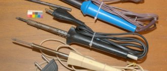
I used this circuit for my regulator about 20 years ago, I still use this soldering iron. Of course, some parts, such as transistors, a neon light bulb, can be replaced with modern ones.
Device details:
- Transistors; KT 315G, MP 25 can be replaced with KT 361B
- Thyristor; KU 202N
- Zener diode; D 814B or with the letter B
- Diode;KD 202Zh
- Fixed resistors: MLT-3k, 2k-2 pcs, 30k, 100 ohm, 470k
- Variable resistor; 100k
- Capacitor; 0.1 µF
As you can see, the device diagram is very simple. Even a beginner can repeat it.
Making a simple soldering iron temperature controller with your own hands
The presented device is built according to the so-called half-wave power regulator. That is, with the thyristor VS 1 fully open, which is controlled by transistors VT 1 and VT 2, one half-wave of the mains voltage passes through the diode VD 1, and the other half-wave through the thyristor. If you turn the slider of the variable resistor R 2 in the opposite direction, then the thyristor VS 1 will close, and the load will have one half-wave that will pass through the diode VD 1:
Therefore, it is impossible to reduce the voltage below 110 volts with this regulator. As practice shows, this is not necessary, since at minimum voltage the temperature of the tip is so low that the tin barely melts.
The part ratings presented in the diagram are selected to work together with high-power soldering irons. If you do not need this, then the power elements, thyristor and diode can be replaced with less powerful ones. If you do not have a two-watt resistor R 5 with a nominal value of 30 kilo ohms, then it can be made up of two series-connected resistors of 15 kilo ohms, like mine:
This device does not require configuration. When assembled correctly and from serviceable parts, it starts working immediately.
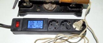
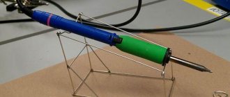
All that remains is to choose the appropriate housing size. Place the soldering iron socket:
It is not necessary to take the fuse out; for example, I have it soldered into the break in the power cord. But the variable resistor needs to be installed in a convenient place and, of course, the scale must be calibrated, for example, in volts:
The resulting regulator is very reliable, which has been tested by time, and it will serve you for many years, and the soldering iron will thank you.
Printed circuit board
Now the main thing. Why is all this needed, what does it give? A simple current regulator does not provide stabilization in any way. If there is very little natural cooling so that the soldering iron does not overheat, then when soldering there will clearly not be enough power.
If it’s normal when soldering, then when idle there will be overheating. Inevitably.
This has a very strong impact. For example, my Chinese tips that came with the soldering iron (copper, by the way) simply melted before our eyes. It’s especially unfortunate for the flat one. With a hatchet.
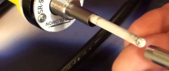
In addition, if it overheats and is left idle for a long time, the tip burns and sometimes it becomes extremely difficult to tin the tip. The solder naturally oxidizes and turns into a gray-black mess. And before soldering you will have to clean the tip every time. In short, the life of the tip and the comfort of soldering are greatly reduced.
A soldering iron modified in this way acquires the features of soldering irons of a completely different price category and quality. This is actually a soldering station.
Another aspect that I checked for myself. Sometimes I solder parts with two soldering irons. Since I now have two such soldering irons, it made sense to check whether there was a potential difference between them that would be detrimental to the part being removed.
Measurements with a voltmeter showed zeros in the range of 20 volts constant and 200 volts alternating. I turned over one of the network plugs. Perhaps it’s just high-quality ceramics in the heaters. True, it’s worth keeping in mind that in the first converted soldering iron, instead of a power supply with zener diodes, there was a Chinese small 12-volt UPS (I didn’t find powerful zener diodes then). Perhaps this is another reason.
Well, why exactly such soldering irons are especially interesting for this alteration.
In normal mode it quickly overheats. This indicates that the heater temperature is too high. And excess power. It has a ceramic heater with a fairly high resistance and a strong change in resistance when heated, which allows you to more accurately monitor the temperature.
Consequently, after the modification it will heat up very quickly, since the voltage is supplied not after the dimmer, in a reduced form, but the full mains voltage.
For the same reason, it will quickly restore the temperature after intensive heat extraction when soldering massive parts.
Review of regulators for soldering iron
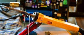
A soldering iron is a special device that is intended for soldering metal elements of various sizes and complexity. In order to change the voltage level on the heating element of the soldering iron, you must use a special power regulator. By smoothly changing the power, you can achieve a smooth decrease and increase in temperature at the soldering iron tip. Read tips on how to choose a soldering iron for microcircuits and other equipment.
Soldering iron with power regulator in the photo
How do they work?
The principle of operation of the regulator for a soldering iron comes down to the fact that using a separate small device, which is connected to the soldering iron wire, you can adjust technical indicators such as temperature, voltage and power.
Switches and Dimmers
The simplest temperature control is used in soldering irons with a switch that allows only two positions, and, accordingly, two temperature values.
At the minimum value, the soldering iron mounted on the stand simply maintains the tip in a heated state, and when you press a key or button, the tip heats up to the maximum temperature at which soldering is performed.
Obviously, of the advantages described above, such a soldering iron only has the ability to save energy. The main task of adjustment - the production of high-quality and safe installation of components - remains impossible.
The second type of adjustable soldering irons is dimmable. Their design involves inserting a dimmer into the break in the power cable - a device that limits the power consumption of the soldering iron.
In this case, it really becomes possible to adjust the temperature of the tip, but this is done due to a voltage drop in the dimmer.
Accordingly, there can be no talk of any cost-effectiveness of such a scheme. But the price of such devices is quite low and can play a decisive role in the choice.
DIY soldering iron regulator
This topic has long been mastered by radio amateurs, who are more interested in a high-quality soldering tool than anyone else. We offer you several popular solutions with electrical diagrams and assembly procedures.
Two-stage power regulator
This circuit works on devices powered by an alternating voltage network of 220 volts. A diode and a switch are connected in parallel to each other into the open circuit of one of the supply conductors. When the switch contacts are closed, the soldering iron is powered in standard mode.
When opened, current flows through the diode. If you are familiar with the principle of alternating current flow, the operation of the device will be clear. The diode, passing current in only one direction, cuts off every second half-cycle, reducing the voltage by half. Accordingly, the power of the soldering iron is reduced by half.
Basically, this power mode is used during long pauses during work. The soldering iron is in standby mode and the tip is not very cool. To bring the temperature to 100%, turn on the toggle switch - and after a few seconds you can continue soldering. When the heating decreases, the copper tip oxidizes less, extending the service life of the device.
Dual-mode circuit using a low-power thyristor
This voltage regulator for a soldering iron is suitable for low-power devices, no more than 40 W. For power control, thyristor KU101E is used (VS2 in the diagram). Despite its compact size and lack of forced cooling, it practically does not heat up in any mode.
The thyristor is controlled by a circuit consisting of a variable resistor R4 (a regular SP-04 with a resistance of up to 47K is used) and a capacitor C2 (electrolyte 22MF).
The operating principle is as follows:
- Standby mode. Resistor R4 is not set to the maximum resistance, thyristor VS2 is closed. The soldering iron is powered through a VD4 diode (KD209), reducing the voltage to 110 volts;
- Adjustable operating mode. In the middle position of resistor R4, thyristor VS2 begins to open, partially passing current through itself. The transition to operating mode is controlled using the VD6 indicator, which lights up when the voltage at the regulator output is 150 volts.
Then you can gradually increase the power, increasing the voltage to 220 volts. We make the printed circuit board according to the size of the regulator body. In the proposed version, a housing from a mobile phone charger is used.
The layout is very simple, can be placed in a smaller case. No ventilation is required, the radio components practically do not heat up.
We assemble the device in the housing and take the resistor handle out.
A classic Soviet 40-watt soldering iron easily turns into a soldering station that works more stable than all Chinese analogues.
Triac power regulator
This option also applies to simple circuits designed for low-power devices. Actually, an adjustable soldering iron is usually needed to work with microcircuits or SMD components. And in this case, more power will be unnecessary.
The circuit design allows you to smoothly regulate the voltage from almost zero to the maximum value. We are talking about 220 volts. The power control element is thyristor VS1 (KU208G). Element HL-1 (MH13) gives the control graph a linear shape and acts as an indicator. Set of resistors: R1 - 220k, R2 - 1k, R3 - 300Ohm. Capacitor C1 – 0.1 microns.
Circuit based on a powerful thyristor
If you need to connect a powerful soldering iron to the regulator, the power block diagram is assembled using a KU202N thyristor. With a load of up to 100W, it does not require cooling, so there is no need to complicate the design with a radiator.
The circuit is assembled on an accessible element base; the parts may simply be in your storage rooms.
Operating principle: The soldering iron supply voltage is removed from the anode of thyristor VS1. Actually, this is an adjustable parameter that controls the temperature. The thyristor control circuit is implemented using transistors VT1 and VT2. The control module is powered by zener diode VD1 together with limiting resistor R5.
The output voltage of the control unit is regulated using a variable resistor R2, which actually sets the power parameters of the connected soldering iron. In the closed state, thyristor VS1 does not pass current, and the soldering iron does not heat up. As the control resistor R2 rotates, the power supply produces an increasing control voltage, opening the thyristor.
The installation diagram consists of two parts.
It is more convenient to assemble the control unit on an etched board so that its microcomponents are grouped without a wired connection.
But the power module of the thyristor and its service elements are located separately, evenly distributed throughout the body.
The assembled circuit “on the knee” looks like this:
Before packing into the case, we check the functionality using a multimeter.
When rotating resistor R2, the voltage at the input to the soldering iron should change smoothly. The circuit is placed in the body of the overhead socket, which makes the design very convenient.
The bottom of the socket is covered with a suitable cover. The ideal option is not just an overhead socket, but a sealed street socket. In this case, the first option was chosen. It turns out to be a kind of extension cord with a power regulator. It is very convenient to use, there are no unnecessary devices on the soldering iron, and the control knob is always at hand.
Microcontroller controller
If you consider yourself an advanced radio amateur, you can assemble a voltage regulator with digital display worthy of the best industrial designs. The design is a full-fledged soldering station with two output voltages - fixed 12 volts and adjustable 0-220 volts.
The low-voltage unit is implemented on a transformer with a rectifier, and is not particularly difficult to manufacture.
The variable voltage control unit is made on the PIC16F628A controller.
Details of the circuit and listing the element base are unnecessary, everything is visible in the diagram. Power control is performed using a triac VT 136 600. Power supply control is implemented using buttons, the number of gradations is 10. The power level from 0 to 9 is shown on the indicator, which is also connected to the controller.
The clock generator supplies pulses to the controller with a frequency of 4 MHz, this is the speed of the control program. Therefore, the controller instantly reacts to changes in the input voltage and stabilizes the output.
The circuit is assembled on a circuit board; such a device cannot be soldered on weight or cardboard.
For convenience, the station can be assembled in a housing for radio crafts, or in any other suitable size.
For safety reasons, 12 and 220 volt sockets are located on different walls of the case. It turned out reliable and safe. Such systems have been tested by many radio amateurs and have proven their performance.
As you can see from the material, you can independently make an adjustable soldering iron with any capabilities and for any budget.
Printed circuit board
Now the main thing. Why is all this needed, what does it give? A simple current regulator does not provide stabilization in any way. If there is very little natural cooling so that the soldering iron does not overheat, then when soldering there will clearly not be enough power.
If it’s normal when soldering, then when idle there will be overheating. Inevitably.
This has a very strong impact. For example, my Chinese tips that came with the soldering iron (copper, by the way) simply melted before our eyes. It’s especially unfortunate for the flat one. With a hatchet.
In addition, if it overheats and is left idle for a long time, the tip burns and sometimes it becomes extremely difficult to tin the tip. The solder naturally oxidizes and turns into a gray-black mess. And before soldering you will have to clean the tip every time. In short, the life of the tip and the comfort of soldering are greatly reduced.
A soldering iron modified in this way acquires the features of soldering irons of a completely different price category and quality. This is actually a soldering station.
Another aspect that I checked for myself. Sometimes I solder parts with two soldering irons. Since I now have two such soldering irons, it made sense to check whether there was a potential difference between them that would be detrimental to the part being removed.
Measurements with a voltmeter showed zeros in the range of 20 volts constant and 200 volts alternating. I turned over one of the network plugs. Perhaps it’s just high-quality ceramics in the heaters. True, it’s worth keeping in mind that in the first converted soldering iron, instead of a power supply with zener diodes, there was a Chinese small 12-volt UPS (I didn’t find powerful zener diodes then). Perhaps this is another reason.
Well, why exactly such soldering irons are especially interesting for this alteration.
In normal mode it quickly overheats. This indicates that the heater temperature is too high. And excess power. It has a ceramic heater with a fairly high resistance and a strong change in resistance when heated, which allows you to more accurately monitor the temperature.
Consequently, after the modification it will heat up very quickly, since the voltage is supplied not after the dimmer, in a reduced form, but the full mains voltage.
For the same reason, it will quickly restore the temperature after intensive heat extraction when soldering massive parts.
Checking the functionality of the regulator
Before installing a new module into the soldering iron body, it is advisable to check whether it copes with its basic functions. There are two main testing methods:
- We plug in the soldering iron with the regulator and check the power readings with a multimeter. When you turn the variable resistor knob, it should gradually increase or decrease.
- We connect the module to the light bulb. By changing its brightness, you can verify that the device is working correctly. If an LED was used in the circuit, this procedure is not necessary; you just need to observe its behavior.
Another important procedure is adjusting the regulator. If you are not satisfied with the operation of the module, you can replace the resistor by installing a part with lower resistance. The main thing here is not to overdo it, so as not to damage the indicator.
Switches and Dimmers
A simple type switch allows you to select a position in two directions. The unit is operated at minimum and maximum output values, allowing only to save energy. At the minimum level, the tip is maintained by the required degree of heating on the stand; pressing the switch warms it up. With a product equipped with the specified type of switch, it is difficult to perform high-quality fusion of metals, because there is no complete setting of parameters. Dimmable varieties of adjustable devices allow you to select important parameters.
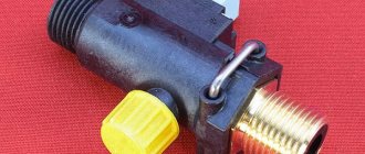
Homemade dimmer for soldering iron
The device includes a dimmer, which is present in the grid between the power cable and the heating element. The adjustment is made by monitoring the voltage; these mechanisms are popular among beginning radio amateurs due to their low price.
Power regulator for soldering iron 20-36 VAC
If the soldering iron operates from a network with reduced voltage, you will have to make a separate regulator for it.
Element base
To make such a device yourself, you will need to prepare the following components in advance:
- Transistor KT815B. If this is not the case, you can install KT815G instead.
- Diode bridge KTs401A. KTs402 B or S is also suitable for the regulator.
- Diodes. For the power regulator it is better to use models from the D9 series.
You will also need capacitors. It is recommended to install oxide elements of type K50-6.
Installation features
To make such a regulator, you will have to order a printed circuit board layout in advance and place the entire element base on it. Particular attention must be paid to resistors. The fact is that their parameters are selected depending on the desired control limit.
It is recommended to place all components on an L-shaped radiator. It is necessary to install a socket on the front side or in the upper part of the regulator body to connect a soldering station.
Capacities and tasks
- Soldering iron for microcircuits - power 10-20 W
- Soldering iron for radio components - power 30-40 W
- Universal soldering iron - 60 W
- Soldering iron for thick wires and large parts - 80-100 W
You can also find more powerful soldering irons on sale - from 100 W, which are used for rough repairs of cabinet structures in outdoor conditions. But for these purposes, in our opinion, it is better to use a special hair dryer or blowtorch.
When answering the question of which soldering iron to choose for microcircuits, we immediately emphasize that the main difficulty in this matter is the simultaneous melting of the soldering points of all the legs of the microcircuit. Therefore, specifically for microcircuits (memory chips, controllers, etc.), you need to carefully use either a soldering hair dryer or a soldering iron to melt the place of each contact and use a special tool (either a copper wire braid or a tin pump) to select tin from it. A soldering iron with a power of 20-30 W is suitable for these purposes.
Control units
More advanced systems have a control unit consisting of a set of regulators and microcircuits. The compactness allows you to place the drawing in the handle of the soldering iron, which is very convenient in the process. The control sensor is located outside the housing, which makes it possible to select an indicator without interrupting the soldering process.
The unit adjusts the parameters of the potential differences of the electrical network, regardless of the modes; with some actions this condition must be met
The varieties of control units can be confusing; if mobility is important, it is better to pay attention to the internal arrangement. External blocks allow for better contact; a type of soldering station that includes a hair dryer is provided
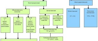
Origin story
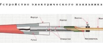
A soldering iron is a tool designed to transfer heat to a material upon contact with it. Its direct purpose is to create a permanent connection by melting solder.
Until the beginning of the 20th century, there were two types of soldering devices: gas and copper. In 1921, German inventor Ernst Sachs invented and registered a patent for a soldering iron, which was heated by electric current. In 1941, Karl Weller patented a transformer-type instrument shaped like a pistol. By passing current through its tip, it quickly heated up.
https://youtube.com/watch?v=35aOf4a1uQk
Twenty years later, the same inventor proposed using a thermocouple in a soldering iron to control the heating temperature. The design included two metal plates pressed together with different thermal expansion. Since the mid-60s, due to the development of semiconductor technologies, soldering tools began to be produced in pulse and induction types.
Heating control
To heat a massive part to the required temperature, you need an equally massive soldering iron tip so that the heating rate is higher than the heat removal rate of the part.
A tool that can simultaneously cope with the tasks posed above is a fairly powerful soldering iron with temperature control.
That is, the maximum power of the soldering iron should be sufficient to heat large leads, and the temperature should be regulated within certain limits and selected in accordance with the operating conditions.
Then the massive tip will have greater thermal inertia and will heat the part to the required degree, without the risk of overheating.
There are several ways to adjust the temperature of the soldering iron:
- maximum-minimum heating (simple switch);
- dimmer adjustment;
- the use of control microcircuits in the handle of the device;
- external control unit;
- using a hair dryer.
https://youtube.com/watch?v=MKZBAqnGoZ4
Using an adjustable soldering iron, in addition to the advantages described above, you can significantly save on electricity consumption for large volumes of work performed, extend the life of the device due to less time operating at maximum power, and reduce the amount of harmful substances released during high-temperature soldering.