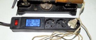
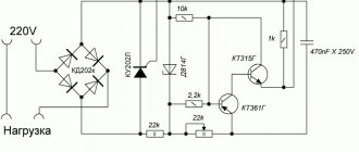
| Hi all! In the last article I told you how to make a voltage regulator for DC. Today we will make a voltage regulator for 220V AC. The design is quite simple to repeat even for beginners. But at the same time, the regulator can take on a load of even 1 kilowatt! To make this regulator we need several components: |
1. Resistor 4.7 kOhm mlt-0.5 (even 0.25 watt will do).
2. A variable resistor 500kOhm-1mOhm, with 500kOhm it will regulate quite smoothly, but only in the range of 220V-120V. With 1 mOhm - it will regulate more tightly, that is, it will regulate with a gap of 5-10 volts, but the range will increase, it is possible to regulate from 220 to 60 volts! It is advisable to install the resistor with a built-in switch (although you can do without it by simply installing a jumper). 3. Dinistor DB3. You can get one from economical LSD lamps. (Can be replaced with domestic KH102). 4. Diode FR104 or 1N4007, such diodes are found in almost any imported radio equipment. 5. Current-efficient LEDs. 6. Triac BT136-600B or BT138-600. 7. Screw terminal blocks. (you can do without them by simply soldering the wires to the board). 8. Small radiator (up to 0.5 kW it is not needed). 9. Film capacitor 400 volt, from 0.1 microfarad to 0.47 microfarad. AC voltage regulator circuit:
Let's start assembling the device. First, let's etch and tin the board. The printed circuit board - its drawing in LAY, is in the archive. A more compact version presented by comrade sergei is here.
Next, we solder a triac and a variable resistor.
Then we solder the capacitor. The photo shows the capacitor from the tinning side, because my example of the capacitor had too short legs.
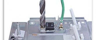
We solder the dinistor. The dinistor has no polarity, so we insert it as you wish. We solder the diode, resistor, LED, jumper and screw terminal block. It looks something like this:
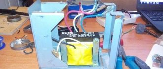
And in the end, the last stage is to install a radiator on the triac.
And here is a photo of the finished device already in the case.
The regulator does not require any additional settings. Video of this device working:
I would like to note that it can be installed not only on a 220V network on conventional appliances and power tools, but also on any other alternating current source with a voltage from 20 to 500V (limited by the maximum parameters of the circuit’s radio elements). [PC]Boil- was with you
Discuss the article AC VOLTAGE REGULATOR
Devices that allow you to control the operation of electrical appliances, adjusting them to optimal characteristics for the user, have become firmly established. One such device is a power regulator. The use of such regulators is in demand when using electric heating and lighting devices and in devices with motors. The circuit design of regulators is varied, so it can sometimes be difficult to choose the best option.
Principle of operation
How does our network voltage stabilizer, which is easy to make with your own hands, work?
After the power is turned on, capacitor C1 is in a discharged state, transistor VT2 is open, and VT2 is closed. Transistor VT3 is also closed. It is through it that current will be supplied to each LED and triac optotron.
Since this transistor is off, the LEDs are not lit, each triac is off, and the load is off. At this time, electric current passes through resistor R1 and enters C1. Next, this capacitor is charged.
The delay interval lasts only three seconds. During this time, all transient processes are carried out, and after completion, the Schmitt trigger is triggered, the basis of which is transistors VT1 and VT2.
Next, the third transistor opens and the load is turned on.
The voltage that comes out from the third winding T1 is rectified by the diode VD2 and capacitor C2. Next, the current passes through the divider R13…14. From R14, a voltage whose level is proportional to the number of volts in the network is included in each non-inverting input of the comparators.
The number of comparators is eight and they are all located on chips DA2 and DA3. At the same moment, a constant reference current enters the inverting input of each comparator. It is supplied by resistor dividers R15…23.
After this, the controller comes into play, which processes the signal at the input of each comparator.
- https://electricadom.com/stabilizator-napryazheniya-kak-vse-sdelat-svoimi-rukami-video.html
- https://amperof.ru/sovety-elektrika/sxema-stabilizatora-napryazheniya-220v.html
- https://lifehacker.ru/how-to-make-steadycam/
- https://ostabilizatore.ru/shema-stabilizatora-naprjazhenija-220v-svoimi-rukami.html
- https://fb.ru/article/360616/shema-stabilizatora-napryajeniya-v-svoimi-rukami-dlya-doma
- https://generatorvolt.ru/ehlektrogenerator/kak-sobrat-stabilizator-napryazheniya-svoimi-rukami.html
Introduction.
Many years ago, I made a similar regulator when I had to earn extra money repairing radios at a customer’s home. The regulator turned out to be so convenient that over time I made another copy, since the first sample was constantly installed as an exhaust fan speed regulator. https://oldoctober.com/
By the way, this fan is from the Know How series, as it is equipped with an air shut-off valve of my own design. Description of the design >>> The material can be useful for residents living on the top floors of high-rise buildings and who have a good sense of smell.
The power of the connected load depends on the thyristor used and its cooling conditions. If a large thyristor or triac of the KU208G type is used, then you can safely connect a load of 200... 300 Watts. When using a small thyristor, type B169D, the power will be limited to 100 Watts.
The simplest DIY electric motor speed controller
When making various homemade products, you have to face a number of problems and find solutions for them. This is the case with various devices that have a commutator electric motor in their design. Very often it is necessary to make the engine have adjustable speed. For these purposes, an engine speed regulator (controller) is used, which you can assemble yourself.
The regulator presented below for electric motors allows not only to ensure a smooth start of the motor and the degree of speed control, but also to protect the motor from overloads. The controller can operate not only from 220 Volts, but also from reduced voltage, up to 110 Volts.
Top 5 transistors
Different types of transistors are used for different purposes, and there is a need to select one.
- KT 315. Supports NPN structure. Released in 1967 but still in use today. Works in dynamic mode and in key mode. Ideal for low power devices. More suitable for radio components.
- 2N3055. Best suited for audio mechanisms, amplifiers. Works in dynamic mode. Easy to use for 12 volt regulator. Conveniently attaches to the radiator. Operates at frequencies up to 3 MHz. Although the transistor can only withstand up to 7 amperes, it pulls powerful loads.
- KP501. The manufacturer intended it to be used in telephones, communication mechanisms and radio electronics. Through it, devices are controlled at minimal cost. Converts signal levels.
- Irf3205. Suitable for automobiles, enhances high frequency inverters. Supports significant current levels.
- KT 815. Bipolar. Has an NPN structure. Works with low frequency amplifiers. Consists of a plastic body. Suitable for pulse devices. Often used in generator circuits. The transistor was made a long time ago and still works today. There is even a chance that it is in an ordinary house where old appliances lie, you just need to take them apart and see if they are there.
What is a 220 V voltage regulator
The abbreviated name of the device in question is RN 0–220 V. The simplest such device is a dimmer for incandescent lamps. The device adjusts the network voltage parameters, increases/decreases the degree of the output signal in a range depending on the value of the potential difference at its output. Maintains the specified voltage of the consumer circuit.
The device regulates (smoothly or stepwise) precisely the voltage value itself, the voltage, on which the power in the range of capabilities of the connected unit also depends. It works with reactive and active loads, you just need to check whether a particular assembly is suitable, especially for the latter. And also you always need to compare what power (Watts) the circuit is designed for.
The RN changes, according to user settings, the level of the output signal from the 220 V network supplied to the load connected to it. Thus, a parameter is set that is suitable for powering a particular device, and more often for adjusting its operation (reducing/increasing the speed of low-power electric motors, light brightness).
The voltage regulator is used:
- to change the speed of small motors of household devices (the speed of a blender, hair dryer), less often, since not all circuits are suitable, for more powerful motors (for example, a drill);
- for other devices whose operation can be customized. And more often (and this is the most correct and effective use) for the light level (dimmer), sound volume, heating of heating elements, soldering iron,
- in all cases, if it is necessary to create a certain voltage on the circuit, for example, 12 V.
Most often, household pH 0–220 V is used for smooth on/off. devices.
Factory models usually also have a microcircuit for stabilizing voltage during voltage surges, ensuring the operation of devices in any mode. According to English standards, a thyristor regulator is called Voltage Controller. RNs are supplied with universal power supplies on which the voltage can be adjusted.
Types, principle of operation, features
The RN on our topic is intended only for alternating voltage, that is, for a regular 220 V home network.
Most often they are assembled based on the following parts:
- thyristors;
- triacs;
- transistors.
The circuits also contain capacitors, constant and tuning resistors. It is the selectors of the latter that carry out the adjustment. Complex assemblies may include microchips.
RNs are most effective for resistive (reactive, ohmic) loads, that is, those that are part of the power consumption of the connected/disconnected consumer. This is resistance to the flow of current, such as a resistor, at the point where electricity is converted into heat.
Resistive loads are heating elements, heating elements, incandescent lamps (not “housekeepers”).
In an inductive load, the current (where it is much lower than with a resistive load) lags behind the voltage, and reactive power is created. These are asynchronous electric motors, electromagnets, chokes, transformers, rectifiers. The launch vehicles will not work with them, or they will, but not effectively, creating a risk of equipment failure. There voltage regulators are not always appropriate.
The thyristor device cannot be used with LED (economical) and fluorescent lamps. Capacitor regulators do not allow smooth voltage changes.
How to Read Technical Data Sheets
As with most things, the answer to this question can be found on the Internet.
Here we describe how you can find reference sheets of technical data for products (their technical descriptions) produced by a particular manufacturer ( Fig. 14 ). First, find the component you are interested in from an email ordering supplier. Then Google the part number and manufacturer's name. Typically, data sheets for that component will be among the first search results. Using sources such as the Mouser Electronics website makes searching even easier by providing a direct link to technical data sheets for many products.
Rice. 14. A typical technical data sheet that includes the relevant technical specifications for a product, in this case a high efficiency LED in a 5mm diameter package.
Let's give an example. Let's say I want to use a red LED like the TLHR5400 from Vishay Semiconductor, which has become so common that I can buy it separately for $0.09 each. Click on the link to the technical data sheet provided by Vishay Semiconductor. Almost immediately, a PDF file page will appear on your computer screen. This data sheet is for LED types TLHR, TLHG and TLHY, which respectively have red, green and yellow colors, indicated by the letters "R", "G" and "Y" in the LED name. I scroll through the document and find the table “OPTICAL ELECTRICAL CHARACTERICS” (optical and electrical characteristics). It contains information that when the current through the LED is 20 mA, it has a typical value (“TYP.”) Forward voltage of 2 V. The word “MAX.” in the table means the maximum value, which is 3 V.
Now let's look at another data sheet since they all have the same shape. I'll choose another LED, Kingbright's WP7113SGC component. I click on the link on the manufacturer's website and I get the second page of the data sheet, where the typical forward voltage is 2.2V, the maximum is 2.5V, and the maximum forward current is 25mA. Also, I found some additional information: the maximum allowable reverse voltage is 5V, and the maximum allowable reverse current is 10uA (meaning a microamp, which is 1000 times smaller than an ampere). This data tells us that we should not apply excess voltage to the LED when connecting with reverse polarity. If the maximum permissible reverse voltage value for an LED is exceeded, there is a danger of its failure. Therefore, always try to maintain the correct polarity when connecting!
Kingbright provides information about the temperature the LED can withstand: 260°C (500°F) for a few seconds. This is useful information because pretty soon we'll be putting aside our alligator clips and using hot solder melted with a soldering iron to connect electrical components. Since we've already destroyed the battery, fuse, and LED in just four experiments, you probably won't see us ruining at least a few more components when determining their temperature limits when exposed to a soldering iron.
In any case, now we know what is needed for the LED to work properly, and we can do all the relevant calculations.
| Fundamentals |
| Ohm's law For reasons I'll explain later, electric current is usually represented by the letter "I". The letter "U" represents voltage and the letter "R" represents resistance, usually represented in ohms (since it is not easy to type the letter "Ω" using most keyboards). Using these symbols, you can write Ohm's law in three different ways: U = I × R.I = U/R.R = U/I.It should be remembered that U is the potential difference (voltage) between two points in a simple circuit, R is the resistance in ohms between those two points, and I is the current in amperes that passes through that circuit between the two points. The letter "I" is used because current strength is measured according to the inductance created by the current, which means the ability of the current to induce (create) a magnetic field. To designate electric current, the use of the letter “A” would raise much fewer questions, but, unfortunately, it is too late to change anything. |
| Basic information |
| What voltage drops across the wire? Usually, we can ignore the resistance of wires, for example, in short-length wires that connect resistances, since it is obvious. However, if you are trying to pass a large amount of current through a long, thin wire, then it becomes important to consider its resistance. How important is this? To determine this, we can again use Ohm's law. Let's assume that a very long piece of wire has a resistance of 0.2 ohms. Let's say we want to pass a current of 15 A through this wire. What voltage will be taken from the circuit due to its resistance? We begin again to write the equation that you already know: R = 0.2 Ohm I = 15 A We want to know the voltage U, the voltage drop, for the wire, so we'll use Ohm's law, which puts the voltage U on the left side of the equation: U = I × R.Now you need to put into this formula the values that were specified in the condition: U = 15 A × 0.2 Ohm = 3 V Three volts is not too much if you have a high voltage source, but if you are using, for example, a car battery with a voltage of 12 V, but a wire of that length will take a quarter of the available voltage in the circuit ( Fig. 15 ). Now you should understand why the wires in cars are quite thick - this is due to the fact that their resistance should be much less than 0.2 ohms. |
| Fundamentals |
| Decimal separator position¹ Legendary British politician Sir Winston Churchill was famous for complaining about “those bloody dots.” He was aware of decimal points. Since Churchill was Chancellor of the Exchequer at this time and was responsible for all government spending, his difficulties with the use of decimal points created quite a lot of problems. Nevertheless, be that as it may, he always brought things to the end, which you will probably do too. Alternatively, you can use a pocket calculator - or the following two basic rules. When performing multiplication: move decimal points Let's assume. You need to multiply 0.04 by 0.005:
When performing division: cancel decimal points Let's assume. You need to divide 0.006 by 0.0002:
|
Practical examples for review
The most popular among radio amateurs are circuits designed to control the brightness of a lamp and change the power of a soldering iron. Such circuits are easy to repeat and can be assembled without the use of printed circuit boards by simple overhead mounting.
Circuits made independently are in no way inferior in performance to factory ones, since they do not require settings and, with working radio components, are immediately ready for use. If you are unable or want to make the device yourself from scratch, you can purchase kits for self-production. Such kits contain all the necessary radio elements, a printed circuit board and a circuit with assembly instructions.
Dominant scheme
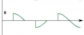
The easiest way to assemble such a device is with a thyristor. The operation of the circuit is based on the ability of the thyristor to open when the input sinusoid passes through zero, as a result of which the signal is cut off and the voltage across the load changes.
The circuit for replicating the thyristor power regulator is based on the use of thyristor VS1, which is used as KU202N. This radio element is made of silicon and has a pnp type structure. Used as a symmetrical switch for medium power signals and switching AC power circuits.
When a voltage of 220V is applied, the input signal is rectified and sent to capacitor C1. As soon as the voltage drop across C1 is equal to the potential difference, at the point between resistances R3 and R4, bipolar transistors VT1 and VT2 open. The voltage level is limited by the zener diode VD1. The signal is sent to the control terminal of KU202N, and capacitor C1 is discharged. When a signal occurs at the control terminal, the thyristor is unlocked. As soon as the capacitor is discharged, VT1 and VT2 close, and the thyristor also closes accordingly. At the next half-cycle of the input signal, everything repeats again.
Such a regulator can be used not only as a dimmer, but also to control the power of a commutator motor. The dominant circuit can operate at currents up to 10 amperes; this value directly depends on the characteristics of the thyristor used, and it must be installed on the radiator.
Soldering iron heating controller
Controlling the power of a soldering iron not only has a positive effect on its service life, preventing the tip and its internal elements from overheating, but also allows you to solder radioelements that are critical to the temperature of the device.
Devices for monitoring the temperature of a soldering iron have been produced for a long time. One of its types was a domestic device, produced under the name “Additional device for an electric soldering iron type P223.” It allowed connecting a low-voltage soldering iron to a 220V network.
The easiest way to make a regulator for a soldering iron is to use a KU208G triac.
Power contacts are connected in series to the load. Therefore, the current flowing through the triac coincides with the load current. To control the key mode, dinistor VS2 is used. Capacitor C1 is charged through resistors: R1 and R2. Operation indication is organized using VD1 and LED. Because it takes time for the voltage across the capacitor to change, a phase shift occurs between the mains voltage and the capacitor voltage. By changing the value of resistance R2, the magnitude of the phase shift is adjusted. The longer the capacitor is charged, the less the triac is in the open state, and therefore the power value is lower.
This regulator is designed to connect a load with a power of up to 300 watts. When using a soldering iron with a power of more than 100 watts, the triac should be installed on a radiator. The manufactured board easily fits on a PCB measuring 25x30 mm and is freely placed in an internal power socket.
Electrical circuits use a voltage regulator to change the output level. Its main purpose is to change the power supplied to the load. Using the device, they control the speed of electric motors, the level of illumination, sound volume, and heating of devices. You can buy a finished product in radio stores, but it’s easy to make a voltage regulator yourself.
Manufacturing Features
There are several ways to make a control device. The easiest way is to purchase a kit containing a ready-made printed circuit board and radio elements necessary for DIY assembly. In addition to them, the kit contains an electrical and circuit diagram describing the sequence of actions. Such kits are called KIT and are intended for the most inexperienced radio amateurs.
Another way involves purchasing radio components yourself and manufacturing a printed circuit board if necessary. Using the second method, you can save money, but it takes more time.
There are many schemes of varying levels of complexity for self-production. But to make a voltage regulator, in addition to the circuit, you will need to prepare the following tools, devices and materials:
- soldering iron;
- multimeter;
- solder;
- tweezers;
- wire cutters;
- flux;
- technical alcohol;
- connecting copper wires.
If you plan to assemble a device consisting of 6 or more elements, then it would be advisable to make a printed circuit board. To do this, you need to have foil PCB, ferric chloride and a laser printer.
The technique of making a printed circuit board at home is called laser ironing (LUT). Its essence is to print a printed circuit board on a glossy sheet of paper, and transfer the image to the PCB using ironing. The board is then immersed in a ferric chloride solution. In it, open sections of copper dissolve, and closed ones with a translated image form the necessary connections.
Read also: Do-it-yourself blowtorch forge
When making the device yourself, it is important to be careful and remember about electrical safety, especially when working with a 220 V AC network. Usually, a correctly assembled regulator from serviceable radio components does not need adjustment and immediately starts working.
Purpose
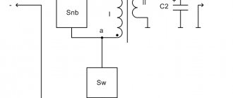
Voltage booster transformers (linear regulators) are used to regulate voltage in individual lines or in a group of lines. They are used, for example, to improve the operation of networks that use transformers without load regulation. Linear regulators allow you to create an additional EMF in the network, which adds up to the network voltage vector and changes it. In Fig. Figure 1 shows a schematic representation of a boost transformer (linear regulator).
Figure 1 – Schematic representation of a linear regulator
Installing a voltage booster transformer allows you to equalize the voltage in the electrical network; eliminate voltage asymmetry in a certain section of the circuit; reduce the dangerous consequences of burning out the neutral conductor
Let's take a look inside your potentiometer
The first thing I want to do is introduce you to how a potentiometer works. This means you have to open it up, which is why your list of parts needed included purchasing two potentiometers, just in case you couldn't put the first one back together.
Most potentiometers are held in place by small metal tabs when assembled. You can probably hook these tabs with your side cutters (wire cutters) or pliers, and then bend them up and slightly to the sides. If you do this, the potentiometer should open as shown in Fig. 2 .
Fig.2.
The wire or conductive film has some resistance (2 kOhm in this case), and when turning the potentiometer axis, any corresponding point of the resistive element (wire or non-wire) is contacted with the central terminal of the potentiometer. After disassembling the potentiometer, you can try to assemble it again, but if this does not work, then you need to take a spare similar potentiometer. To test your potentiometer, you need to use a multimeter to measure its resistance in ohms, while ensuring constant contact of the test leads with the leads of the potentiometer and rotating its axis in one direction and the other, as shown in Fig. 3 .
Fig.3.
Chip contacts
Manufactured in a universal transistor package, allowing it to be placed on a board or heat sink. The most common model LM317 is found in the TO-220 case with the letter “T” at the end of the marking. The letter "t" indicates the housing type.
The pinout of the LM317 stabilizer is made using three contacts. If you look at the device from the front, the first pin on the left (Adj) is the adjustable pin, the middle pin (Vout) is the output, and the last pin on the right (Vin) is the input.
- Vin is a pin; it receives an input voltage that needs to be adjusted. For example, it may be supplied with 12V, which the device will step down to 10V at Vout.
- Vout is the pin to which the voltage is output. The surface of the heatsink is connected to this pin of the microcircuit.
- Adjustable (Adj) is a pin that allows you to adjust the output voltage through a trimmer resistor.
Found in various types of housings.
Contact numbers of different types of microcircuit housings.
Integral stabilizer
The devices are assembled using small-sized microcircuits capable of operating at an input voltage of up to 26-30 V, delivering a constant 12-volt current of up to 1 Ampere.
A special feature of these radio components is the presence of 3 legs - “input”, “output” and “adjustment”. The latter is used to connect an adjustment resistor, which is used to adjust the microcircuit and prevent it from overloading. More convenient and reliable equalizers assembled on the basis of stabilizing microcircuits are gradually replacing analogues assembled on discrete elements.
Basic functions of the speed controller
The use of such converters allows you to achieve many goals, namely:
- the possibility of stepwise acceleration and reduction of electric motor speed, which leads to reduced loads and less electrical energy consumption;
- you can carry out a smooth start, and with instantaneous maximum acceleration, the motor receives ultra-high loads, overheating the windings and other drives;
- as a means of additional protection of electronic mechanisms;
- reduction in maintenance costs for power units and pumps, as the risks of drive failures, as well as individual mechanisms, are reduced.
Welding machines, voltage stabilizers, PCs, TVs, etc. cannot do without similar built-in devices.
Making your own device
Initially we need a 12 volt voltage regulator circuit. It needs to be etched and cleaned before it can be used in practice. Next, you should solder the necessary parts as indicated. And as a result, here is a pulse voltage stabilizer (12 volts, 1.5 Amperes), which can be used in a car to adjust the backlight. For convenience and protection, the entire device can be placed in a special container. It is advisable to use plastic as its material, which can easily withstand significant temperatures and ensures tightness. Conductive metals should only be used if there are insulators on the wires and all parts of parts that could potentially cause an electric shock.
Construction and details
Now let's move on to the design of the device. Diode bridges, a capacitor, resistor R2 and diode VD6 are installed on a circuit board measuring 55x35 mm, made of foil getinax or textolite with a thickness of 1...2 mm (Fig. 9.7).
The following parts can be used in the device. Transistor - KT812A(B), KT824A(B), KT828A(B), KT834A(B,V), KT840A(B), KT847A or KT856A. Diode bridges: VD1...VD4 - KTs410V or KTs412V, VD6 - KTs405 or KTs407 with any letter index; diode VD5 - series D7, D226 or D237.
Variable resistor - type SP, SPO, PPB with a power of at least 2 W, constant - BC, MJIT, OMLT, S2-23. Oxide capacitor - K50-6, K50-16. Network transformer - TVZ-1-6 from tube TVs, TS-25, TS-27 - from the Yunost TV or any other low-power one with a secondary winding voltage of 5...8 V.
The fuse is designed for a maximum current of 1 A. The toggle switch is TZ-S or any other network switch. XP1 is a standard power plug, XS1 is a socket.
All elements of the regulator are housed in a plastic case with dimensions of 150x100x80 mm. A toggle switch and a variable resistor equipped with a decorative handle are installed on the top panel of the case. The socket for connecting the load and the fuse socket are mounted on one of the side walls of the housing.
On the same side there is a hole for the power cord. A transistor, transformer and circuit board are installed at the bottom of the case. The transistor must be equipped with a radiator with a dissipation area of at least 200 cm2 and a thickness of 3...5 mm.
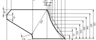
Rice. Printed circuit board of a powerful 220V mains voltage regulator.
The regulator does not need to be adjusted. With proper installation and serviceable parts, it begins to work immediately after being plugged into the network.
Now some recommendations for those who want to improve the device. The changes mainly concern increasing the output power of the regulator. So, for example, when using the KT856 transistor, the power consumed by the load from the network can be 150 W, for KT834 - 200 W, and for KT847 - 250 W.
If it is necessary to further increase the output power of the device, several parallel-connected transistors can be used as a control element by connecting their corresponding terminals.
Probably, in this case, the regulator will have to be equipped with a small fan for more intensive air cooling of semiconductor devices. In addition, the diode bridge VD1...VD4 will need to be replaced with four more powerful diodes, designed for an operating voltage of at least 600 V and a current value in accordance with the consumed load.
Devices of the D231...D234, D242, D243, D245...D248 series are suitable for this purpose. It will also be necessary to replace VD5 with a more powerful diode, rated for current up to I A. Also, the fuse must withstand a higher current.
Triac power regulators operate using phase control. They can be used to change the power of various electrical devices operating using alternating voltage.
The devices may include electric incandescent lamps, heating devices, alternating current electric motors, transformer welding machines, and many others. They have a wide range of adjustment, which gives them a wide range of applications, including in everyday life.
Regulation with stabilization
To obtain the specified voltage or load current parameters, stabilizers are used. In them, the output voltage or current is compared with a reference value, and at a minimum specified change, the regulator is automatically compensated by the control of the corresponding semiconductor device. There are a huge number of different schemes for various stabilizers. The easiest to use are integrated circuits.
- Linear voltage stabilizer with adjustment on TL431 and NPN transistors
Appearance and connection diagram of the 12 V stabilizer microcircuit
Such ready-made stabilizers are very convenient for powering LEDs both in cars and in lighting systems. When powered from a 220 volt network, a step-down transformer with a rectifier is required, connected to the input. Since in many cases the load parameters are very specific, special voltage and current stabilizers are made. They can operate in both continuous and pulse modes. But that's a completely different story...
5 common questions asked by beginning radio mechanics; 5 best transistors for regulators, circuit composition test
An electrical voltage regulator is needed so that the voltage can be stabilized. It ensures reliable operation and longevity of the device.
The regulator consists of several mechanisms.
TEST:
The answers to these questions will allow you to find out the composition of the 12 volt voltage regulator circuit and its assembly.
- What resistance should the variable resistor have?
a) 10 kOhm
DIY soldering iron power regulator: proven working circuits (6 pcs)
Not everyone likes to buy unknown things. And some people find it more pleasant to make a soldering iron power regulator with their own hands, because this is also experience. Most circuits are assembled using triacs and thyristors; now they are easier to find than transistors. They are also easier to work with, since they are either open or closed, which allows you to make circuits simpler.
Choose any case
Simple thyristor circuits
When choosing a power regulator circuit for a soldering iron, two things are important: power and parts availability. The soldering iron power regulator presented below is assembled using widely used parts that are not a problem to find. The maximum current is 10 A, which is more than enough to perform any kind of work and for soldering irons with a power of up to 100 W. The thyristor in this circuit is used KU202n
Pay attention to the bridge connection. There are many circuits with connection errors. This option works
Tested more than once
This option is working. Tested more than once.
Temperature controller circuit for a soldering iron using a thyristor
When assembling the circuit, be sure to place the thyristor on the radiator; the larger it is, the better. The circuit is simple, but when it is turned on, it creates interference. You can’t listen to the radio nearby, and to remove interference, we connect a 200 pF capacitor in parallel with the load, and a choke in series. The choke parameters are selected depending on the regulated load, but since soldering irons are usually no more than 80-100 W, the choke can be made at 100 W. To do this, you will need a ferrite ring with an outer diameter of 20 mm, on which about 100 turns are wound with a wire with a cross-section of 0.4 mm².
Another drawback of the diagram translated above is that the soldering iron “itches” noticeably. Sometimes you can put up with this, sometimes you can’t. To eliminate this phenomenon, you can select the parameters of capacitor C1 so that when the variable resistor is set to maximum, the connected lamp barely glows.
On other elements but also without interference
The above regulator can be used for any load. Let's give another analogue, but using a different element base. You can regulate not only the power/temperature of the soldering iron, but also any other load with a small inductive component.
A modified circuit for regulating the power of a soldering iron and any other load with the ripple effect eliminated
There is pulsation here, but its frequency is high and it will not be perceived by our vision. So it can be used not only as a dimmer for a soldering iron, but also to regulate the light from a regular incandescent lamp. Is a diode bridge needed to regulate the heating power of a soldering iron? It won't hurt, but it's not necessary.
On a thyristor with high sensitivity
This circuit allows you to smoothly change the temperature of the soldering iron from 50% to 100%. There are two indicators - power and power. The power presence LED always lights up when turned on, but at 75% power the glow is brighter. The power indicator changes the intensity of the glow depending on the operating mode.
Power regulator for soldering iron without interference
In order for the regulator to fit into the case of a mobile phone charger, resistances are used of SMD type (1206). All resistors are installed on the board, except for R 10. Some can be composite (we assemble the required value from series-connected resistors).
For normal operation of the circuit, a sensitive thyristor (with a low control current) and a low state holding current (about 1 mA) is required. For example, KT503 (designed for voltage 400 V, control current 1 mA). The rest of the element base is indicated in the diagram.
If assembled, but the voltage is not adjustable
If the assembled regulator does not regulate anything - the temperature of the soldering iron does not change - the problem is in the thyristor. The scheme seems to be working, but nothing happens. The reason is a thyristor with low sensitivity. The currents flowing in the circuit are not sufficient to open. In this case, it is worth installing an analogue with higher sensitivity (lower control currents).
One of the housing options in which you can hide a homemade power regulator for a soldering iron
The regulator may still work, but the soldering iron begins to “itch.” This problem is solved by installing a choke at the output (in front of the soldering iron). The capacity must be selected - it depends on the soldering iron. The second solution is an analog control circuit, and this is a different circuit.
Well, if you have problems with operation, look for either faulty parts or incorrectly selected components. This is usually the problem.
Simple circuits
To control the output voltage for low-power devices, you can assemble a simple voltage regulator using 2 parts. All you need is a transistor and a variable resistor. The operation of the circuit is simple: with the help of a variable resistor, induction occurs (the transistor is turned on).
If the control terminal of the resistor is in the lower position, then the voltage at the output of the circuit is zero. And if the pin moves to the upper position, then the transistor becomes open as much as possible, and the output signal level will be equal to the voltage of the power source minus the drop in the potential difference across the transistor.
When the resistance changes, the output voltage is adjusted. Depending on the type of transistor, the switching circuit also changes. The smaller the value of the variable resistor, the smoother the adjustment will be. The disadvantage of the circuit is the excessive heating of the transistor, so the greater the difference between Uin and Uout, the more it will heat up.
This circuit is convenient to use for adjusting the rotation of computer fans or other weak motors, as well as LEDs.
Triac type
To regulate alternating voltage, triac regulators are used, with which you can control the power of a soldering iron or light bulb. By assembling the circuit using an inexpensive and accessible triac BT136, you can change the load power within 100 watts.
To assemble the circuit you will need:
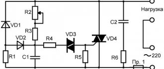
| Name | Denomination | Analogue |
| Resistor R1 | 470 kOhm | |
| Resistor R2 | 10 kOhm | |
| Capacitor C1 | 0.1 µF x. 400 V | |
| Diode D1 | 1N4007 | 1SR35–1000A |
| LED D2 | BL-B2134G | BL-B4541Q |
| Dinistor DN1 | DB3 | HT-32 |
| Triac DN2 | BT136 | KU 208 |
The principle of operation of the regulator is as follows: through a chain consisting of a dinistor DN1, a capacitor C1 and a diode D1, current flows to the triac DN2, which leads to its opening. The opening moment depends on the capacitance C1, which is charged through resistors R1 and R2. Accordingly, changing the resistance R1 controls the charging rate of C1.
Despite its simplicity, this circuit does an excellent job of adjusting the voltage of heating devices that use tungsten filament. But since such a circuit does not have feedback, it cannot be used to control the speed of a commutator motor.
Voltage relay
For car enthusiasts, an important element is a device that maintains the voltage of the on-board network within established limits when various factors change, for example, generator speed, turning on or off the headlights. The devices used for this work on the same principle - voltage stabilization by changing the excitation current. In other words, if the input signal level changes, the device reduces or increases the excitation current.
A self-assembled circuit of a voltage regulator relay should:
- work in a wide temperature range;
- withstand power surges;
- be able to turn off when starting the engine;
- have a small drop in potential difference.
In a simplified way, the principle of operation can be described as follows: when the voltage exceeds the set value, the rotor is turned off, and when it normalizes, it starts again. The main element of the circuit is the PWM stabilizer LM 2576 ADJ.
The TC4420EPA chip is designed for instantaneous switching of the transistor. Using resistor R3, capacitor C1 and zener diodes VD1, VD2, the microcircuit and field-effect transistor are protected. Resistors R1 and R2 set the reference voltage for the stabilizer. DD1 controls the operation of the field-effect transistor and rotor. Diode D2 is used to limit the control voltage. Inductance L1 ensures smooth discharge of the rotor through diodes D4 and D5 when the circuit is opened.
Managed power supply
When constructing various circuits, radio amateurs often collect voltage sources. By soldering a DC voltage regulator with your own hands, it can be used as a controlled power supply in the range from 0 to 12V.
The assembled voltage source consists of 2 parts: a power supply and a parametric voltage regulator. The first part is made according to the classical scheme: step-down transformer - rectifier unit. The type of transformer, rectifier diodes and transistor used determines the power of the device. The alternating voltage of the network is reduced in the transformer to 11 volts, after which it goes to the diode bridge VD1, where it becomes constant. Capacitor C1 is used as an anti-aliasing filter. The signal is sent to a parametric stabilizer consisting of resistor R1 and zener diode VD2.
A resistor R2 is connected in parallel to the zener diode, which changes the output voltage level. The transistors are connected according to a simplified emitter follower circuit, and when voltage appears at their transitions, they begin to operate in current amplification mode. That is, the signal taken from R2 is supplied to the output of the device through transistors, which reduce its value by the amount of its saturation. Thus, the more voltage is applied to them, the more they open and the more power goes to the output.
This regulated power supply can handle loads up to three amps, meaning it can provide up to 30 watts of power. If you have experience, then the circuit is soldered by surface mounting using wires of any cross-section.
Generator voltage regulator
The generator converts electricity. Without a generator, the entire on-board system of the car would not work. A special sensor is connected to the magnet winding. Simple springs are the driving device. A small lever is used for the comparison device. The group of contacts plays the role of an actuator. A constant resistance is an adjustment element that is often used in machines.
During operation of the generator, a current arises at its output. The resulting current passes into the winding of the magnetic relay. As a result, a magnetic field appears and, under its influence, the lever arm moves apart. A spring begins to act on it and plays the role of a comparing device. When the current exceeds the required values, the contacts on the magnetic relay move apart. At this time, the constant resistance in the circuit is turned off. Less current flows into the winding.
Perhaps it is useful for everyone to know what the accuracy class of an electric meter is.
From the network
Single-phase AC motors also allow you to control the rotation of the rotor.
Collector machines
Such motors are found on electric drills, jigsaws and other tools. To reduce or increase the speed, it is enough, as in previous cases, to change the supply voltage. There are also solutions for this purpose. The structure connects directly to the network. The adjusting element is a triac, which is controlled by a dinistor. The triac is placed on the heat sink, the maximum load power is 600 W.
If there is a suitable LATR, you can do all this using it.
Two phase motor
The device, which has two windings - starting and working, is two-phase in principle. Unlike three-phase, it has the ability to change the rotor speed. The characteristic of its rotating magnetic field is not circular, but elliptical, which is due to its design. There are two possibilities for controlling the speed:
- Change the amplitude of the supply voltage (Uy),
- Phase - change the capacitance of the capacitor.
Such units are widely used in everyday life and in production.
Regular asynchronous
Three-phase electric machines, despite their ease of operation, have a number of characteristics that need to be taken into account. If you simply change the supply voltage, the torque will change within a small range, but no more. In order to regulate speed within a wide range, you need quite complex equipment, which is difficult and expensive to simply assemble and set up.
For this purpose, the industry has launched the production of frequency converters that help change the speed of the electric motor in the desired range.
The asynchronous machine gains momentum in accordance with the parameters set on the frequency driver, which can be changed in a wide range. The converter is the best solution for such engines.
How to connect 5 parts of a 12 volt regulator.
Variable resistor 10 kOhm.
This is a 10kohm variable resistor. Changes the current or voltage in an electrical circuit, increases resistance. This is what regulates the voltage.
Radiator. Needed to cool devices in case they overheat.
Resistor for 1 com. Reduces the load on the main resistor.
How to avoid 3 common mistakes when working with a triac.
- The letter after the triac code indicates its maximum operating voltage: A – 100V, B – 200V, C – 300V, D – 400V. Therefore, you should not take a device with the letters A and B to adjust 0-220 volts - such a triac will fail.
- A triac, like any other semiconductor device, gets very hot during operation; you should consider installing a radiator or an active cooling system.
- When using a triac in load circuits with high current consumption, it is necessary to clearly select the device for the stated purpose. For example, a chandelier with 5 bulbs of 100 watts each will consume a total current of 2 amperes. When choosing from the catalog, you need to look at the maximum operating current of the device. Thus, the MAS97A6 triac is designed for only 0.4 amperes and will not withstand such a load, while the MAS228A8 is capable of passing up to 8 A and is suitable for this load.
Using Ohm's Law
Ohm's law is very useful. For example, it helps us determine whether a particular component in a given circuit is safe to use. Instead of subjecting a component to high voltage until it burns out, we can predict how it will perform.
For example, in the beginning, when you turned the potentiometer shaft, you didn't really know how long you could do it without the LED going bad. Therefore, it would be useful to know exactly what resistance should be connected in series with the LED in order to adequately protect it while obtaining maximum brightness.