In order to obtain high-quality and beautiful soldering, it is necessary to correctly select the power of the soldering iron and ensure a certain temperature of its tip, depending on the brand of solder used. I offer several circuits of homemade thyristor temperature controllers for soldering iron heating, which will successfully replace many industrial ones that are incomparable in price and complexity.
Attention, the following thyristor circuits of temperature controllers are not galvanically isolated from the electrical network and touching the current-carrying elements of the circuit can lead to electric shock!
To adjust the temperature of the soldering iron tip, soldering stations are used, in which the optimal temperature of the soldering iron tip is maintained in manual or automatic mode. The availability of a soldering station for a home craftsman is limited by its high price. For myself, I solved the issue of temperature regulation by developing and manufacturing a regulator with manual, stepless temperature control. The circuit can be modified to automatically maintain the temperature, but I don’t see the point in this, and practice has shown that manual adjustment is quite sufficient, since the voltage in the network is stable and the temperature in the room is also stable.
Classic thyristor regulator circuit
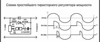
The classic thyristor circuit of the soldering iron power regulator did not meet one of my main requirements, the absence of radiating interference into the power supply network and the airwaves. But for a radio amateur, such interference makes it impossible to fully engage in what he loves. If the circuit is supplemented with a filter, the design will turn out to be bulky. But for many use cases, such a thyristor regulator circuit can be successfully used, for example, to adjust the brightness of incandescent lamps and heating devices with a power of 20-60 W. That's why I decided to present this diagram.
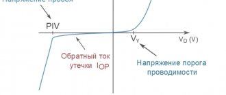
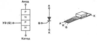
In order to understand how the circuit works, I will dwell in more detail on the principle of operation of the thyristor. A thyristor is a semiconductor device that is either open or closed. to open it, you need to apply a positive voltage of 2-5 V to the control electrode, depending on the type of thyristor, relative to the cathode (indicated by k in the diagram). After the thyristor has opened (the resistance between the anode and cathode becomes 0), it is not possible to close it through the control electrode. The thyristor will be open until the voltage between its anode and cathode (labeled a and k in the diagram) becomes close to zero. It's that simple.
The classical regulator circuit works as follows. AC mains voltage is supplied through the load (incandescent light bulb or soldering iron winding) to a rectifier bridge circuit made using diodes VD1-VD4. The diode bridge converts alternating voltage into direct voltage, varying according to a sinusoidal law (diagram 1). When the middle terminal of resistor R1 is in the extreme left position, its resistance is 0 and when the voltage in the network begins to increase, capacitor C1 begins to charge. When C1 is charged to a voltage of 2-5 V, current will flow through R2 to the control electrode VS1. The thyristor will open, short-circuit the diode bridge and the maximum current will flow through the load (top diagram).
When you turn the knob of the variable resistor R1, its resistance will increase, the charging current of capacitor C1 will decrease and it will take more time for the voltage on it to reach 2-5 V, so the thyristor will not open immediately, but after some time. The greater the value of R1, the longer the charging time of C1 will be, the thyristor will open later and the power received by the load will be proportionally less. Thus, by rotating the variable resistor knob, you control the heating temperature of the soldering iron or the brightness of the incandescent light bulb.
Above is a classic circuit of a thyristor regulator made on a KU202N thyristor. Since controlling this thyristor requires a larger current (according to the passport 100 mA, the real one is about 20 mA), the values of resistors R1 and R2 are reduced, R3 is eliminated, and the size of the electrolytic capacitor is increased. When repeating the circuit, it may be necessary to increase the value of capacitor C1 to 20 μF.
Types and characteristics of regulators
Devices designed to control power values are divided according to the adjustment method:
- thyristor;
- triac;
- phase (dimmer).
By type of output signal:
- stabilized;
- not stabilized.
Adjustment is carried out when powered by both direct and alternating voltage. You can control the voltage or current.
Depending on their location, regulators can be portable or stationary, installed in any position: vertical, ceiling, horizontal, mounted on a special DIN rail or built-in. Structurally, they are carried out both on specialized printed circuit boards and using surface-mounted installation.
The main characteristics that you should pay attention to are the following parameters:
- smooth adjustment;
- operating and peak power input;
- input operating voltage range;
- voltage setting range supplied to the load;
- terms of Use.
The simplest thyristor regulator circuit
Here is another very simple circuit of a thyristor power regulator, a simplified version of the classic regulator. The number of parts is kept to a minimum. Instead of four diodes VD1-VD4, one VD1 is used. Its operating principle is the same as the classical circuit. The circuits differ only in that the adjustment in this temperature controller circuit occurs only over the positive period of the network, and the negative period passes through VD1 without changes, so the power can only be adjusted in the range from 50 to 100%. To adjust the heating temperature of the soldering iron tip, no more is required. If diode VD1 is excluded, the power adjustment range will be from 0 to 50%.
If you add a dinistor, for example KN102A, to the open circuit from R1 and R2, then the electrolytic capacitor C1 can be replaced with an ordinary one with a capacity of 0.1 mF. Thyristors for the above circuits are suitable, KU103V, KU201K (L), KU202K (L, M, N), designed for a forward voltage of more than 300 V. Diodes are also almost any, designed for a reverse voltage of at least 300 V.
The above circuits of thyristor power regulators can be successfully used to regulate the brightness of lamps in which incandescent light bulbs are installed. It will not be possible to adjust the brightness of lamps that have energy-saving or LED bulbs installed, since such bulbs have electronic circuits built in, and the regulator will simply disrupt their normal operation. The light bulbs will shine at full power or flicker and this may even lead to their premature failure.
The circuits can be used for adjustment with a supply voltage of 36 V or 24 V AC. You only need to reduce the resistor values by an order of magnitude and use a thyristor that matches the load. So a soldering iron with a power of 40 W at a voltage of 36 V will consume a current of 1.1 A.
Do it yourself
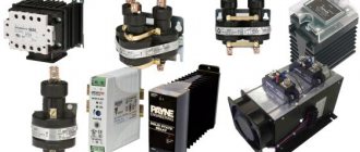
Today, the range of triac regulators on sale is not very large. And, although the prices for such devices are low, they often do not meet consumer requirements. For this reason, we will consider several basic circuits of regulators, their purpose and the element base used.
Device diagram
The simplest version of the circuit, designed to work with any load. Traditional electronic components are used, the control principle is phase-pulse.
Main components:
- triac VD4, 10 A, 400 V;
- dinistor VD3, opening threshold 32 V;
- potentiometer R2.
The current flowing through potentiometer R2 and resistance R3 charges capacitor C1 with each half-wave. When the voltage on the capacitor plates reaches 32 V, the dinistor VD3 opens and C1 begins to discharge through R4 and VD3 to the control terminal of the triac VD4, which opens to allow current to flow to the load.
The opening duration is regulated by selecting the threshold voltage VD3 (constant value) and resistance R2. The power in the load is directly proportional to the resistance value of potentiometer R2.
An additional circuit of diodes VD1 and VD2 and resistance R1 is optional and serves to ensure smooth and accurate adjustment of the output power. The current flowing through VD3 is limited by resistor R4. This achieves the pulse duration required to open VD4. Fuse Pr.1 protects the circuit from short circuit currents.
Triacs should be selected according to the load size, based on the calculation of 1 A = 200 W.
Elements used:
- Dinistor DB3;
- Triac TS106-10-4, VT136-600 or others, the required current rating is 4-12A.
- Diodes VD1, VD2 type 1N4007;
- Resistances R1100 kOhm, R3 1 kOhm, R4 270 Ohm, R5 1.6 kOhm, potentiometer R2 100 kOhm;
- Capacitor C1 0.47 µF (operating voltage from 250 V).
Note that the scheme is the most common, with minor variations. For example, a dinistor can be replaced with a diode bridge, or an interference-suppressing RC circuit can be installed in parallel with the triac.
A more modern circuit is one that controls the triac from a microcontroller - PIC, AVR or others. This circuit provides more accurate regulation of voltage and current in the load circuit, but is also more complex to implement.
Triac power regulator circuit
Assembly
The power regulator must be assembled in the following sequence:
- Determine the parameters of the device on which the device being developed will work. Parameters include: number of phases (1 or 3), the need for precise adjustment of output power, input voltage in volts and rated current in amperes.
- Select the type of device (analog or digital), select elements according to load power. You can check your solution in one of the programs for modeling electrical circuits - Electronics Workbench, CircuitMaker or their online analogues EasyEDA, CircuitSims or any other of your choice.
- Calculate the heat dissipation using the following formula: voltage drop across the triac (about 2 V) multiplied by the rated current in amperes. The exact values of the voltage drop in the open state and the rated current flow are indicated in the characteristics of the triac. We get the power dissipation in watts. Select a radiator according to the calculated power.
- Purchase the necessary electronic components , heatsink and printed circuit board.
- Lay out contact tracks on the board and prepare sites for installing elements. Provide mounting on the board for a triac and radiator.
- Install the elements on the board using soldering. If it is not possible to prepare a printed circuit board, then you can use surface mounting to connect the components using short wires. When assembling, pay special attention to the polarity of connecting the diodes and triac. If there are no pin markings on them, then test them using a digital multimeter or a “dragstick”.
- Check the assembled circuit with a multimeter in resistance mode. The resulting product must correspond to the original design.
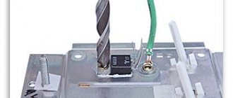
- Securely attach the triac to the radiator. Don’t forget to lay an insulating heat transfer gasket between the triac and the radiator. The fastening screw is securely insulated.
- Place the assembled circuit in a plastic case.
- Remember that there is dangerous voltage at the terminals of the elements.
- Turn the potentiometer to minimum and perform a test run. Measure the voltage at the regulator output with a multimeter. Smoothly turn the potentiometer knob to monitor the change in output voltage.
- If the result is satisfactory, then you can connect the load to the output of the regulator. Otherwise, it is necessary to make power adjustments.
Read also: Why oil does not flow to the chainsaw chain
Triac power radiator
Power adjustment
The power control is controlled by a potentiometer, through which the capacitor and the capacitor discharge circuit are charged. If the output power parameters are unsatisfactory, you should select the resistance value in the discharge circuit and, if the power adjustment range is small, the potentiometer value.
In almost any radio-electronic device, in most cases there is power adjustment. You don’t have to look far for examples: these are electric stoves, boilers, soldering stations, various motor rotation controllers in devices.
The Internet is full of ways to assemble a 220 V voltage regulator with your own hands. In most cases, these are circuits based on triacs or thyristors. The thyristor, unlike the triac, is a more common radio element, and circuits based on it are much more common. Let's look at different design options based on both semiconductor elements.
Modern triac regulator circuit
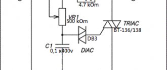
Below is a modern circuit diagram of a triac power regulator. In order to understand the principle of operation of a power regulator on a triac, you need to imagine how it works.
Triacs, unlike thyristors, can operate not only in DC circuits, but also in AC circuits. This is their main difference. The triac also operates in key mode - either open or closed. To open the transition A1-A2, you need to apply a voltage of 2-5 V to the control electrode G relative to pin A1. The triac will open and not close until the voltage between terminals A1-A2 becomes zero.
The triac power regulator circuit operates as follows. AC mains voltage is supplied through the load (incandescent light bulb or soldering iron winding) to terminal A1 of triac VS2 and one of the terminals R2. When the middle terminal of resistor R2 is in the extreme left position, its resistance is 0 and when the voltage in the network begins to increase, capacitor C1 quickly charges. When C1 is charged to a voltage of 30 V, a breakdown of the dinistor VS1 occurs and the current flows to the control electrode G VS2 and the junction of the triac A1-A2 opens (graph 1).
When you turn the knob of variable resistor R2, its resistance will increase, the charging current of capacitor C1 will decrease and it will take more time for the voltage on it to reach 30 V. Therefore, the triac will open after some time. The greater the value of R2, the longer the charging time of C1 will be and the triac will open with a longer delay. This way, less energy will be supplied to the load.
The given classic circuit of a triac power regulator can also operate at a network voltage of 127, 24 or 12 V. It is only enough to reduce the value of the variable resistor. In the above circuit, the power is regulated not from 0 volts, but from 30, which is more than enough for practical use. This circuit was successfully repeated when repairing the electronic circuit for controlling the rotation speed of a blender motor.
Thyristor circuits
You can regulate the total power of the soldering iron quite simply if you use analog or digital soldering stations . The latter are quite expensive to use, and it is quite difficult to assemble them without much experience. While analog devices (considered to be essentially total power regulators) are not difficult to create yourself.
A fairly simple circuit of the device that will help regulate the power indicator on the soldering iron.
- VD - KD209 (or similar in its general characteristics).
- R 1 - resistance with a special rating of 15 kOhm.
- R2 is a resistor that has a special AC current rating of about 30 kOhm.
- Rn is the total load (in this case a special pendulum will be used instead).
Such a regulation device can control not only the positive half-cycle; for this reason, the power of the soldering iron will be several times less than the nominal one. Such a thyristor is controlled using a special circuit, which carries two resistances, as well as a capacitance. The charging time of the condensate (it will be regulated by a special resistance R2) affects the duration of opening of such a thyristor.
Thyristor circuit of the regulator does not emit interference
The main difference between the circuit of the presented soldering iron power regulator and those presented above is the complete absence of radio interference into the electrical network, since all transient processes occur at a time when the voltage in the supply network is zero.
When starting to develop a temperature controller for a soldering iron, I proceeded from the following considerations. The circuit must be simple, easily repeatable, components must be cheap and available, high reliability, minimal dimensions, efficiency close to 100%, no radiated interference, and the possibility of upgrading.
The temperature controller circuit works as follows. The AC voltage from the supply network is rectified by the diode bridge VD1-VD4. From a sinusoidal signal, a constant voltage is obtained, varying in amplitude as half a sinusoid with a frequency of 100 Hz (diagram 1). Next, the current passes through the limiting resistor R1 to the zener diode VD6, where the voltage is limited in amplitude to 9 V, and has a different shape (diagram 2). The resulting pulses charge the electrolytic capacitor C1 through diode VD5, creating a supply voltage of about 9 V for microcircuits DD1 and DD2. R2 performs a protective function, limiting the maximum possible voltage on VD5 and VD6 to 22 V, and ensures the formation of a clock pulse for the operation of the circuit. From R1, the generated signal is supplied to the 5th and 6th pins of the 2OR-NOT element of the logical digital microcircuit DD1.1, which inverts the incoming signal and converts it into short rectangular pulses (diagram 3). From pin 4 of DD1, pulses are sent to pin 8 of D trigger DD2.1, operating in RS trigger mode. DD2.1, like DD1.1, performs the function of inverting and signal generation (Diagram 4).
Please note that the signals in diagram 2 and 4 are almost the same, and it seemed that the signal from R1 could be applied directly to pin 5 of DD2.1. But studies have shown that the signal after R1 contains a lot of interference coming from the supply network, and without double shaping the circuit did not work stably. And installing additional LC filters when there are free logic elements is not advisable.
The DD2.2 trigger is used to assemble a control circuit for the soldering iron temperature controller and it works as follows. Pin 3 of DD2.2 receives rectangular pulses from pin 13 of DD2.1, which with a positive edge overwrite at pin 1 of DD2.2 the level that is currently present at the D input of the microcircuit (pin 5). At pin 2 there is a signal of the opposite level. Let's consider the operation of DD2.2 in detail. Let's say at pin 2, logical one. Through resistors R4, R5, capacitor C2 will be charged to the supply voltage. When the first pulse with a positive drop arrives, 0 will appear at pin 2 and capacitor C2 will quickly discharge through the diode VD7. The next positive drop at pin 3 will set a logical one at pin 2 and through resistors R4, R5, capacitor C2 will begin to charge.
The charging time is determined by the time constant R5 and C2. The greater the value of R5, the longer it will take for C2 to charge. Until C2 is charged to half the supply voltage, there will be a logical zero at pin 5 and positive pulse drops at input 3 will not change the logical level at pin 2. As soon as the capacitor is charged, the process will repeat.
Thus, only the number of pulses specified by resistor R5 from the supply network will pass to the outputs of DD2.2, and most importantly, changes in these pulses will occur during the voltage transition in the supply network through zero. Hence the absence of interference from the operation of the temperature controller.
From pin 1 of the DD2.2 microcircuit, pulses are supplied to the DD1.2 inverter, which serves to eliminate the influence of the thyristor VS1 on the operation of DD2.2. Resistor R6 limits the control current of thyristor VS1. When a positive potential is applied to the control electrode VS1, the thyristor opens and voltage is applied to the soldering iron. The regulator allows you to adjust the power of the soldering iron from 50 to 99%. Although resistor R5 is variable, adjustment due to the operation of DD2.2 heating the soldering iron is carried out in steps. When R5 is equal to zero, 50% of the power is supplied (diagram 5), when turning at a certain angle it is already 66% (diagram 6), then 75% (diagram 7). Thus, the closer to the design power of the soldering iron, the smoother the adjustment works, which makes it easy to adjust the temperature of the soldering iron tip. For example, a 40 W soldering iron can be configured to run from 20 to 40 W.
Temperature controller design and details
All parts of the thyristor temperature controller are placed on a printed circuit board made of fiberglass. Since the circuit does not have galvanic isolation from the electrical network, the board is placed in a small plastic case of a former adapter with an electrical plug. A plastic handle is attached to the axis of the variable resistor R5. Around the handle on the regulator body, for the convenience of regulating the degree of heating of the soldering iron, there is a scale with conventional numbers.
The cord coming from the soldering iron is soldered directly to the printed circuit board. You can make the connection of the soldering iron detachable, then it will be possible to connect other soldering irons to the temperature controller. Surprisingly, the current consumed by the temperature controller control circuit does not exceed 2 mA. This is less than what the LED in the lighting circuit of the light switches consumes. Therefore, no special measures are required to ensure the temperature conditions of the device.
Microcircuits DD1 and DD2 are any 176 or 561 series. The Soviet thyristor KU103V can be replaced, for example, with a modern thyristor MCR100-6 or MCR100-8, designed for a switching current of up to 0.8 A. In this case, it will be possible to control the heating of a soldering iron with a power of up to 150 W. Diodes VD1-VD4 are any, designed for a reverse voltage of at least 300 V and a current of at least 0.5 A. IN4007 (Uob = 1000 V, I = 1 A) is perfect. Any pulse diodes VD5 and VD7. Any low-power zener diode VD6 with a stabilization voltage of about 9 V. Capacitors of any type. Any resistors, R1 with a power of 0.5 W.
The power regulator does not need to be adjusted. If the parts are in good condition and there are no installation errors, it will work immediately.
The circuit was developed many years ago, when computers and especially laser printers did not exist in nature, and therefore I made a drawing of the printed circuit board using old-fashioned technology on chart paper with a grid pitch of 2.5 mm. Then the drawing was glued with Moment glue onto thick paper, and the paper itself was glued to foil fiberglass. Next, holes were drilled on a homemade drilling machine and the paths of future conductors and contact pads for soldering parts were drawn by hand.
The drawing of the thyristor temperature controller has been preserved. Here is his photo. Initially, the rectifier diode bridge VD1-VD4 was made on a KTs407 microassembly, but after the microassembly was torn twice, it was replaced with four KD209 diodes.
Phase regulator
Phase control is used to smoothly start various types of motors or control current when charging a battery. One type of such device is a dimmer.
The basis of the work lies in changing the opening angle of the key thyristor, as a result of which the load receives signals with the initial part of the half-cycle cut off, and the effective voltage value is reduced.
The advantage of this type of regulation is its low cost due to the use of inexpensive radio components. But the main disadvantage is a significant ripple factor and low power factor of the output signal.
Often, low-frequency microcircuits are used in the design of this type of regulator. Thanks to this, the regulator is able to quickly change power. Phase regulators are rarely stabilized using zener diodes; usually the role of a stabilizer is performed by thyristors operating in pairs.
How to reduce the level of interference from thyristor regulators
To reduce interference emitted by thyristor power regulators into the electrical network, ferrite filters are used, which are a ferrite ring with wound turns of wire. Such ferrite filters can be found in all switching power supplies for computers, televisions and other products. An effective, noise-suppressing ferrite filter can be retrofitted to any thyristor regulator. It is enough to pass the wire connecting to the electrical network through the ferrite ring.
The ferrite filter must be installed as close as possible to the source of interference, that is, to the installation site of the thyristor. The ferrite filter can be placed both inside the device body and on its outside. The more turns, the better the ferrite filter will suppress interference, but simply threading the power cable through the ring is sufficient.
The ferrite ring can be taken from the interface wires of computer equipment, monitors, printers, scanners. If you pay attention to the wire connecting the computer system unit to the monitor or printer, you will notice a cylindrical thickening of insulation on the wire. In this place there is a ferrite filter for high-frequency interference.
It is enough to cut the plastic insulation with a knife and remove the ferrite ring. Surely you or someone you know has an unnecessary interface cable from an inkjet printer or an old CRT monitor.
DIY power regulator for a soldering iron
Let's look at an example of making a current regulator with your own hands. For example, we will regulate the power of a soldering iron. Regulation in such a device allows you to avoid overheating the soldering area and can protect the soldering iron tip from burnout.
This type of device has been produced for quite a long time. One of its types was a domestic device called “Additional device for electric soldering iron type P223.” It allowed the use of a low-voltage soldering iron with a voltage of 36 volts, powered from a 220 V network.
Triac regulator KU208G
The device circuit is quite interesting and easy to implement. Its distinctive feature is the use of a neon light bulb.
The capacitor, about 0.1 μF, is designed to generate a sawtooth pulse and protect the control circuit from interference. Resistors are used to limit the current, and with the help of a variable resistor the current is regulated, its value is about 220 kOhm. The neon light allows linear control and is also an indicator. You can control the adjustment based on the intensity of its brightness.
The disadvantage of such a scheme will be poor awareness of the power of the soldering iron. To visually display the values of the set value, with a sufficient level of radio training, you can use a microcontroller, for example, pic16f628a. It will also be possible to perform electronic power control on it, eliminating the need for a variable resistor.
Adjustment on the integral stabilizer
Another way to control power is to use integrated stabilizers. Using such a device, it is very easy to make a dimmer for a 12 volt voltage regulator. This device is easy to assemble and has built-in protection; it can be used both to connect a 12 V soldering iron and an LED strip. Typically, a variable resistor is connected to the input of the control electrode of the microcircuit. The disadvantage is the strong heating of the stabilizing chip.
The alternating voltage of the 220 V network is reduced through a transformer to 16-18 volts. Then, through a diode bridge and a smoothing capacitor, the rectified value is supplied to the input of the linear stabilizer. Using a variable resistor, by changing the operating characteristics of the microcircuit, the required output voltage is set. This voltage will be stabilized and in our case will be 12 volts.
When making devices yourself, be careful and remember about safety precautions when working with a 220 V AC network. As a rule, a correctly made regulator made from serviceable parts does not require adjustment and immediately starts working.