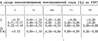
Even perfect welding cannot protect the weld from damage. Sooner or later, this place becomes the weakest in the part and becomes deformed, so protective materials must be used during welding work. These include inert gases and fluxes. The latter are not so common in the domestic environment, but in production, submerged arc welding is very common. It will be discussed further below.
Features of submerged arc welding
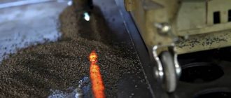
Do not think that submerged arc welding is some completely new welding method. It was invented a long time ago, at the end of the 19th century, and the essence lies in the same use of filler wire and non-consumable electrodes. However, the equipment has constantly improved, and instead of gas covering the entire weld area, only flux is used. It has a powdery consistency and is poured over the seam.
Such a composition, under the influence of high temperatures, also begins to release gas, which will protect the parts being welded from oxides. When the powder burns out, only easily removable slag will remain, and if the product is not completely used, it can easily be saved until next time.
Before you do submerged arc cooking, you will need to select:
- mode;
- electrodes;
- filler wire.
Just like with any other welding work, you will need to properly shape the edges and degrease the parts. But here it will also be important to choose a flux, since it exists in different forms.
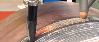
Flux protects the weld from oxides
Advantages and disadvantages
The submerged arc welding process itself has its positive and negative features. Among the advantages:
- Automation to achieve the most precise welds. Automation allows you to set all parameters electronically, so current, wire - everything is supplied and controlled by itself.
- The release of flux continues throughout the entire creation of the seam, which is why its efficiency is higher.
- Can be cooked with high current.
- The cooking speed is adjustable and can be very high.
- The weld pool can be increased.
- The seam is of high quality.
- The ability to assemble elements of complex structures quickly, efficiently and with little effort.
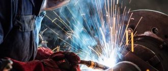
- Safety for welders, as they are not close to the parts being welded.
- You can use 2 electrodes simultaneously, powered by one current source.
Types of fluxes
These products can be divided into groups according to their chemical composition and method of creation. Flux can be saline, oxide or mixed. Here:
- Salt ones are better suited for electric welding of titanium or steel, nickel-plated or chrome-plated. Salt fluxes include fluoride and chloride salts.
- Oxide ones contain oxides of active metals, as well as silicon. This makes them best used for low carbon steels.
- Mixed ones are useful for multi-component alloys and many different metals. This is facilitated by a composition containing metal oxides and salts in different proportions.
There are only two manufacturing methods - fused or non-fused, which is also called ceramic. Fused ones are made from quartz sand, as well as manganese ore, which are mixed, melted, and then granules are formed. This flux is very suitable for low alloy steel.
The ceramic composition includes oxidizing agents and salts of amphoteric metals. First, they are crushed, then mixed with liquid glass until smooth. Then it is granulated and calcined. Such fluxes have the structure of a fine powder, and it is selected specifically for the grade of steel that will be worked with, since it only works with complex nickel or iron-nickel alloys.
Submerged Arc Welding Technology
In order for the welding process to proceed correctly, you need to choose the right automatic submerged arc welding technology. There are three basic methods:
- manual;
- auto;
- semi-automatic.
The process of manual cooking is clear. Manual equipment is used here, so the welder himself regulates the direction and speed of the electrode. The current strength and the supply of flux interacting with the electrode are adjusted using buttons directly on the device.
The semi-automatic method will allow you to automate only some processes, the rest require management. The way the wire is fed, the angle of the electrode, and the current strength are subject to an automatic process. At this time, the welder independently controls the movement of the arc. For semi-automatic devices, you can change the current supply parameters directly during operation.
In automatic submerged arc welding, the speed of movement of the electrode and its direction, as well as the wire feed speed, are set by software. Workers are needed here only to create that very welding program, as well as quality control.
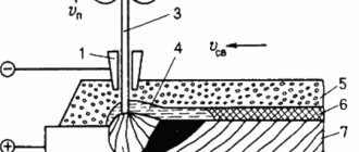
Submerged arc welding diagram
All three of these methods, despite their differences, involve some common steps in submerged arc welding:
- Removal of oxide film.
- Fastening parts to the welding plate.
- Selection of settings and development of a plan.
- Selection of flux.
- Floating wire installation.
- Welding, where you need to carefully monitor the consumption of flux and wire to avoid damage.
After finishing the work, you just need to wait until the parts have cooled, clean the seam and put the flux into sealed containers.
The technology of the welding process using flux is described in detail in GOST 8713-79. It tells about all three methods, selection of materials, setup of equipment. It also shows all the types of welded joints that can be made using each of the three methods.
Influence of the selected automatic welding mode on the penetration depth and weld width
- The influence of current and voltage of the welding arc.
As the current increases, both arc pressure and heat output increase. Accordingly, the penetration of the metal becomes deeper. However, the width of the welded joint remains virtually unchanged.As the arc voltage increases, its mobility also increases. At the same time, the proportion of heat spent on melting the flux also increases. At the same time, the welded joint becomes wider, while the penetration depth changes little.
- Effect of electrode wire diameter and welding speed.
When choosing a larger electrode diameter and a constant current value, the depth of metal penetration decreases. The width of the connection increases due to the fact that the mobility of the arc increases.As the welding speed increases, the penetration depth and joint width decrease. This occurs because the amount of metal melted is reduced compared to operation at a lower speed.
- Influence of the type of welding current and its polarity.
Simultaneously with the change in polarity and type of current, the shape and size of the connection change. The reason lies in the large changes in the amount of thermal energy that occurs on the arc (its anode and cathode). The penetration depth will decrease from 40 to 50% with direct polarity of direct current and by 15–20% with alternating current. And this is in comparison with direct current of reverse polarity.Therefore, a welded joint of small width, in which the penetration depth must be quite large (an example would be a butt weld or a fillet joint without groove), should be performed using direct current of reverse polarity.
- Effect of electrode wire stickout.
Wire stickout increases with increasing heating and melting rates. Consequently, the volume of the weld pool increases due to the metal of the electrode wire, which creates an obstacle to the melting of the base metal. Accordingly, the penetration depth decreases. Knowing this feature, it is possible to increase its productivity during automatic surfacing.Sometimes (mostly during the same automatic surfacing process) the electrode is moved with different amplitudes and frequencies across the edges. This greatly changes both the size and shape of the weld joint. Thus, the penetration depth decreases and the product seam width increases.
This welding method reduces the possibility of burn-through during the creation of butt joints in which the gap between the edges is quite large. The same can be achieved when working with double electrodes, placing them across the welding movement. When they are placed along the welding movement, the penetration depth will increase.
- Influence of the angle of inclination of the electrode or welded edges.
When the electrode is tilted forward, molten metal may leak into the weld pool. For this reason, the penetration depth may decrease and the joint width may increase. If you tilt the electrode back, the welding arc will cut off the molten metal from the working area. As a result, the penetration depth will decrease and the width of the connection will increase.By analogy with the above, when a welded joint is made downhill, the depth of penetration decreases and the width of the seam increases. And when connecting on the rise, the opposite process occurs - the depth of penetration increases and the width of the seam decreases.
Welding mode selection
There are several modes that always need to be selected for each individual task.
| Metal thickness, mm | Wire diameter, mm | Welding current, A | Voltage, V | Welding speed, m/h |
| 3 | 2 | 250 — 500 | 28 — 30 | 48 — 50 |
| 5 | 2 | 400 — 450 | 28 — 30 | 38 — 40 |
| 10 | 5 | 700 — 750 | 34 — 38 | 28 — 30 |
| 20 | 5 | 750 — 800 | 38 — 42 | 22 — 24 |
| 30 | 5 | 950 — 1000 | 40 — 44 | 16 — 18 |
The modes from the table are suitable for low-carbon, medium-carbon and high-carbon steel.
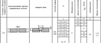
STRUCTURAL ELEMENTS OF CONNECTIONS AND MATERIALS
2.1. The design and location of the elements to be connected, the class and grade of steel must comply with the requirements of the project.
2.2. Reinforcing bars should be made of steel classes AI ... A-III according to GOST 5781-75 with a diameter dн
= 8 ... 16 mm, length 80 ... 250 mm (Fig. 1).
2.3. Rolled steel must have a width of at least 50 mm and a thickness of at least 8 mm. Rolled steel grades must meet the requirements of chapters SNiP II-21-75 and SNiP II-23-81.
2.4. Galvanized steel profiled flooring must have a width of the welded shelf (straight section) of at least 50 mm with a thickness of no more than 1 mm. The thickness of the zinc coating should not exceed 35 microns.
2.5. Minimum distances from the axis of the rod (see Fig. 1) to the edge of a flat rolled steel element to
and galvanized flooring
b
must be at least 1.5
dH
, while
k - b <
0.5 mm (see clause 5.6 of these Recommendations).
2.6. The minimum distance between the axes of the rods welded in the longitudinal direction of the deck must be at least 70 mm.
Rice. 1. Fragment of a steel structure
1 - galvanized profiled flooring; 2 —
frame channel; 3 - T-welded rod
Equipment used
To perform automatic submerged arc welding, the following technical equipment will be required:
- Welding plate. Installation of welding slabs will require a concrete base, since the slabs themselves are made of materials that are resistant to constant high temperatures and temperature changes.
- Floating wire. It usually has a thickness of 0.3 to 12 mm, and is made from the same material as the materials being welded.
- A non-consumable electrode that has a heavy alloy core and a ceramic braid.
- System supplying flux particles. It consists of a reservoir and a hose, the diameter of which will be sufficient to work with the electrode.
- A control system that is more developed in automatic devices and less developed in semi-automatic ones.
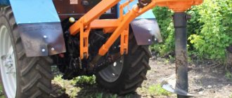
Welding tractor for automatic submerged arc welding
Automatic welding under a layer of flux is not difficult to perform, because most of the process will be automated, and the welder will only need to correctly configure the equipment and select the correct flux agent for welding.
GENERAL PROVISIONS AND SCOPE OF APPLICATION
1.1. These Recommendations should be used to guide the installation welding of T-joints of rods and galvanized steel profiled decking to flat elements of steel structures.
1.2. The recommendations apply to welding reinforcing bars with a diameter of up to 16 mm from steel classes AI ... A-III, galvanized profiled decking up to 1 mm thick and rolled steel with a thickness of at least 8 mm, made of low-carbon and low-alloy steels.
1.3. Test methods, additional technological instructions, design issues, rules for production and acceptance of work, safety precautions, certification of welders and their admission to work must be carried out in accordance with the instructions of GOST 10922-75, SNiP II-21-75, SNiP II-23-81 , Instructions SN 393-78, GOST 12.3.003-75.
1.4. Welders who have mastered welding technology, operating rules for new equipment, and have passed a qualification commission are allowed to perform the work regulated by these Recommendations.