11/17/2021 Author: VT-METALL
From this material you will learn:
- Basic welding mode parameters
- Ratio of current to electrode thickness during welding
- Selecting the electrode diameter when welding metals
- Arc Length Options
- Selecting polarity and current type
- Tilt of the electrode and the workpiece during welding
- Parameters of gas shielded welding mode
- Effect of welding speed
Welding modes and parameters change when performing welding work depending on the type of workpiece, thickness and properties of the metal. If the recommended standards are observed, the weld will be of high quality and the connection itself will be reliable.
Welding parameters are easy to follow; for certain types, ready-made tables have been developed that take into account the main factors. It is enough to study them once and then cook them like clockwork. What are these parameters and what is their difference, read in our material.
Basic welding mode parameters
Welding mode refers to the main characteristics of the welding process, due to which welded joints of specified parameters, shapes and sizes are obtained. In this case, these characteristics can be: current density in the electrode, strength of the cooking current, speed of the cooking process, grade and granulation of flux, arc voltage, shielding gas consumption.
VT-metall offers services:
In order to determine which welding mode is required, it is necessary to determine the thickness and type of structure, as well as the composition of the metals. Based on the data received, the desired mode is set. There are two groups of factors on which the quality of welding depends: primary and secondary.
Stationary arc welding
Random fluctuations in the electrode wire feed speed and arc length can disrupt the stability of the process and lead to short circuits. arc breakage. To avoid this, it is necessary to change the melting rate of the electrode, i.e. Vary the welding current accordingly.
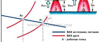
The current-voltage characteristic of the arc (volt-ampere characteristic of the arc) in protective gases with a consumable electrode has an increasing character.
At a certain point in the stable welding process, the electrode wire feed speed Vп1 is equal to the melting speed Vpl1. In this case, the current and voltage parameters were determined by the operating point A1 with arc length ld1. Let us assume that due to malfunctions in the wire feed mechanism, the feed speed has decreased. Then a relative melting rate ΔVmel = Vmel1 - Vп2 arises, which leads to the movement of the operating point to a new position - A2. It is characterized by a decrease in welding current (Δl), which leads to a decrease in the initial melting rate. The welding process returned to point A1 with arc length ld1. This process is called self-regulation along the arc length. It becomes more intense with a more rigid voltage-ampere characteristic of the power source.
When welding from a source with a rigid characteristic, the welder adjusts the current mode by adjusting the wire feed speed. However, this changes the length of the arc and the voltage on it. To maintain the required arc length, when setting the mode, you should adjust the current-voltage characteristic of the power supply, moving from one (I) to another (II).
The stability of the arc, especially in the ceiling position, as well as the size of the weld and its quality depend on the type of transfer of electrode metal through the arc gap. There are three types of transfer.
1. Large droplet transfer with arc short circuits. Droplets are formed 1.5 times larger than the diameter of the electrode wire. The process is accompanied by short circuits with a natural pulse-arc process determined by the mode parameters. The voltage on the arc periodically decreases to 0 and at the moment of drop separation it increases to the operating value. The current at the moment of a short circuit increases, which leads to the detachment of a drop of electrode metal.
The process proceeds with metal spattering, which worsens the appearance of the welded joint, leading to lack of penetration and excessive convexity of the seam.
2. Medium drop transfer without short circuits.
The arc burns continuously, and the electrode metal is transferred through the arc in droplets whose diameter is close to the diameter of the wire.
Welding occurs with periodic changes in arc voltage and welding current.
The pulse-arc process depends on the parameters of the welding mode and is also accompanied by spattering, which reduces the quality of the weld.
3. Jet transfer.
The arc burns continuously, the melted end of the electrode is extended into a cone, from which drops measuring less than 2/3 of the electrode diameter flow into the weld pool. The mass of the drop is small, so the electrode metal is easily transferred to the pool during welding in all spatial positions.
Spattering during jet transfer is negligible. Productivity is high. Jet transfer can be obtained in argon. In carbon dioxide, this transfer is achieved at high welding current densities or with wires activated by rare earth elements
Controlled transfer of electrode metal with the required droplet sizes is successfully achieved using a pulsed-arc process, when the arc voltage and welding current are periodically changed.
Ratio of current to electrode thickness during welding
Electrodes are selected depending on the thickness of the seam being welded and the welding method. They can be in a 1:1 ratio. So, for a seam with a thickness of 3-4 mm, an electrode measuring 3 mm is suitable. Multi-profile parts are welded gradually. They usually start with a 4 mm electrode.
If you do not make a calculation at the beginning of work and take an electrode with a smaller diameter, then the seam will not be filled completely, which will lead to a weak connection.
When choosing an electrode, you need to refer to the tables to determine the current strength. For a diameter of 3 mm, the required current is 65–100 A. If you have a vertical seam, then the minimum value of its diameter should be at least 4 mm. It should be remembered that when horizontal welding, the current must be reduced by 15–20%.
The welding current value is calculated by the formula:
I = K × d,
Where:
I – welding current strength in amperes;
K – coefficient;
d – electrode diameter in millimeters.
When vertical welding, the current is reduced by 10%; in ceiling seams, it is reduced to 20% of the obtained value. From this table you can select the coefficient K:
| Electrode diameter, mm | K, A/mm |
| 1-2 | 25–30 |
| 3-4 | 35–40 |
| 5-6 | 45–50 |
Influence of speed on weld configuration
As the welding speed increases, the weld width decreases. The depth of penetration first tends to increase, and then it begins to decrease.
Compensation is carried out by increasing the current value. At a high welding speed, undercutting of the welded seam may occur, on both sides. This is due to heating that is insufficient to obtain a high-quality seam.
If the metal is thick, it makes sense to weld it with narrow seams, while ensuring high speed. Slow welding can lead to the appearance of defects in the metal in the form of pores.
Selecting the electrode diameter when welding metals
For a more correct choice of electrode, it is necessary to clarify the following indicators: the thickness of the product being welded, the location of the seam (horizontal, vertical, ceiling), the shape of the edges and the type of connection. The main indicator is the thickness of the metal, and other factors serve for more accurate adjustments.
In this table you can select the electrode diameter you need based on your indicators:
| Thickness of welded metal | Electrode diameter |
| 1,5 | 1,6 |
| 2 | 2 |
| 3 | 3 |
| 4-5 | 3-4 |
| 6–8 | 4 |
| 9–12 | 4-5 |
| 13–15 | 5 |
| 16–20 | 5 or more |
The root layer can be made with electrodes with a diameter of 2.5-3 mm. To do this, the edges must be cut. Ceiling seams are most often made with electrodes with a diameter of 3-3.2 mm. The tabular data is ideal for horizontal seams.
Arc Length Options
In welding, arc voltage is the most important parameter that determines its length. To put it simply, this is the distance from the end of the electrode to the object. This indicator directly depends on the electrode and is presented in tables. A piece of work is considered to be of high quality if there is not a single imperfection throughout the entire seam. In this profession, experience is important; only a professional is able to follow such a subtle nuance.
We recommend articles:
- Butt welded joint: types, execution technology
- Welding arc: its properties, types, principle of operation
- Lap joint: welding for a wide range of applications
Combustion becomes stable if the arc voltage is increased. With such welding, the likelihood of air entering the seam zone increases, and the elements contained in the wire burn out, resulting in the formation of pores. The arc ignition process includes three stages: a short circuit of the electrode to the workpiece, after which the electrode is withdrawn by 3–6 mm and a stable arc discharge occurs.
Mode depending on arc voltage
Arc voltage is related to its length. Typically the voltage is set in the range of 20-36 V. It increases as the arc length increases. The length of the arc can be short, medium and long.
Arc length is the distance from the tip of the electrode to the metal being welded. To make a quality connection, you need to ensure a stable arc size. It is believed that for beginners it is easier to maintain an average arc size. It is possible to make a high-quality seam with a short arc, but this requires experience and professionalism.
Selecting polarity and current type
Welding machines are capable of converting household alternating current into direct current. It is important not to confuse the polarity. It involves connecting the part to “+” and the electrode to “-”. The specialist selects the mode parameter based on the properties of the part.
For welding cast iron parts, straight polarity is suitable. It is also suitable for medium carbon steel with a thickness of 5 mm.
When connecting low-carbon steel and thin-sheet structures, reverse polarity is chosen.
Pulse arc welding
Pulse-arc (non-stationary arc) welding using the MIG/MAG method is possible with low welding current in all spatial positions of the seam with minimal spatter and high-quality seam formation.
There are two main types of electrode metal transfer:
- with continuous arc burning - “long arc”;
- with short circuits of the arc gap - “short arc”
The peculiarity of pulsed-arc welding with a consumable electrode is that the process of transfer of electrode metal can be controlled. When welding with a “long arc”, two types of transfer are possible:
- one pulse - one drop;
- one pulse - a few drops.
Short arc transfer is typical for carbon dioxide welding. Instability and increased spattering of the electrode metal are determined by the properties of the power source and depend on the nature of the change in instantaneous power both during the arcing period and during a short circuit.
In pulsed arc welding using the MIG/MAG method, synergistic process control is effective.
Tilt of the electrode and workpieces during welding
It is important to take into account the angle of inclination of the electrode when working with a semi-automatic machine and to correctly calculate the welding modes. In such work, the rod in relation to the seam should deviate from the norm by 10°. The depth and width of the joint depends on the location of the rods to the joint.
The connection expands, and the depth indicators decrease, provided that welding occurs at an angle forward, due to which the arc drives a wave of melt in front of itself, through which the metal is melted.
The melt will flow to the end of the cooking zone if you select the backward tilt mode. The electric arc has a direct effect on the products being connected. Due to this, the depth of penetration of the joint increases and the width of the seam decreases.
To ensure high-quality filling of the seam, it is recommended to tilt the part at an angle of 8–10°. Otherwise, the molten metal may flow down or lack of penetration will remain. When welding pipes, it is impossible to change their angle, so welding is done from top to bottom.
The benefits of making the right choice
Correctly selected parameters will ensure a high-quality metal connection that can last for many years. The use of ready-made formulas makes it easier to select parameters. But this does not exempt you from studying GOSTs and other regulatory materials.
An experienced welder must cope with a non-standard situation and make adjustments. The correct choice of welding characteristics, in particular, the speed at which it will be carried out, will allow you to obtain high-quality and durable seams.
Parameters of gas shielded welding mode
The welding mode is determined depending on the diameter of the wire and the strength of the welding current. Specialists increase gas consumption to improve gas protection, reduce welding speed, and use protective screens during work.
During welding, gas is supplied to the combustion zone. It displaces air from the arc combustion zone, thereby protecting the weld pool from oxygen and nitrogen from the air. The process is divided into welding in active (CO2, H2, O2, etc.) and inert (He, Ar, Ar+He, etc.) gases.
Consumable and non-consumable electrodes can be used in welding. To a greater extent, specialists work with consumable electrodes. This method is inexpensive when welding carbon and low-alloy steels, so it occupies one of the first places in terms of production volume among mechanized fusion welding methods. When using wire:
- with a diameter of up to 1 mm, and a current from 60 to 160 A, gas flow should be up to 8 liters per minute.
- with a diameter of up to 1.2 mm, and a current strength from 100 to 250 A, gas flow should be up to 9–12 liters per minute.
- with a diameter of up to 1.4 mm, and a current strength of 120 to 320 A, gas flow should be up to 12–15 liters per minute.
- with a diameter of up to 1.6 mm, and a current strength from 249 to 380 A, gas flow should be up to 15–18 liters per minute.
- with a diameter of up to 2 mm, and a current from 280 to 450 A, gas flow should be up to 18–20 liters per minute.
This is the average gas consumption when welding with a semi-automatic machine. There are also indirect factors that can affect additional gas consumption, for example, if welding takes place outside. In this case, the gas will quickly evaporate, thereby increasing its consumption.
Don’t forget about the quality of the gas itself, because if the gas is diluted, you simply won’t be able to keep the indicators normal; there will be excess consumption in any case.
Welding current
Current has defining properties: type, polarity and strength. By type, current is divided into direct and alternating. Polarity can be direct or reverse.
Most welding machines operate on direct current. The difference between direct current and alternating current is that direct current does not change in direction or magnitude. Thus, it ensures the stability of the arc. The only disadvantage of direct current in the process of joining metals is the possibility of a magnetic blowing effect. It occurs when connecting large structures, when an extraneous magnetic field (from magnetized products) affects the magnetic field of the arc. In this case, the arc begins to “run out” beyond the area where the seam is located and combustion stability decreases sharply. This disadvantage can be combated by
- fencing the work area with special screens that protect from “extra” magnetic fields
- grounding of welded surfaces
- identify possible options for using alternating current
The advantage of working on direct current is a stable arc and the ability to select polarity. Direct polarity is also called electrode-negative, reverse polarity is also called electrode-positive. Reverse polarity occurs when the electrode is connected to the positive and the metal to the negative. With direct polarity, the opposite is true. The difference between the polarities is as follows. The laws of physics say that where the plus is connected, that element heats up more. Thus, with straight polarity, the metal product heats up more. This polarity should be used to join thick parts, since this process requires more melting of the metal to obtain a good weld. If direct polarity is used on a thin product, it will “burn” and the seam will turn out to be of poor quality. For thin metals, reverse polarity is carried out.
The amount of current is determined by the characteristics of a particular welding machine. In modern models, these indicators are indicated in the instructions. If for some reason you do not have instructions, then the current strength can be selected depending on the diameter of the electrode used. It is not allowed to use a current strength that is more suitable for a particular electrode. In this case, the electrode coating used to make the connection will be damaged and the arc will operate unstably. Using an electrode that is too large also has a bad effect on the process of joining metals: the current density decreases, the arc “runs away,” its length changes, and the weld does not turn out smooth and of high quality.