Arc welding modes (ARC) are a set of measures, indicators and parameters that must be maintained and observed for the correct implementation of a manual arc connection.
Manual arc welding modes can be defined as the conditions for the normal functioning of the process of joining parts under various circumstances. Depending on different parameter indicators, the correct choice of modes for a specific type of welding joint and the choice of welding mode in general is carried out. Conventionally, the parameters of the manual arc welding mode can be divided into two types: basic and additional. The main parameters of the welding mode for manual arc welding include the diameter of the electrode, the properties and magnitude of the welding current, and the arc voltage. Additional parameters include the position of the seam on the product, the composition and thickness of the metal, the speed of joining the product and the electrode coating. Let's consider each of them separately.
Welding current
Current has defining properties: type, polarity and strength. By type, current is divided into direct and alternating. Polarity can be direct or reverse.
Most welding machines operate on direct current. The difference between direct current and alternating current is that direct current does not change in direction or magnitude. Thus, it ensures the stability of the arc. The only disadvantage of direct current in the process of joining metals is the possibility of a magnetic blowing effect. It occurs when connecting large structures, when an extraneous magnetic field (from magnetized products) affects the magnetic field of the arc. In this case, the arc begins to “run out” beyond the area where the seam is located and combustion stability decreases sharply. This disadvantage can be combated by
- fencing the work area with special screens that protect from “extra” magnetic fields
- grounding of welded surfaces
- identify possible options for using alternating current
The advantage of working on direct current is a stable arc and the ability to select polarity. Direct polarity is also called electrode-negative, reverse polarity is also called electrode-positive. Reverse polarity occurs when the electrode is connected to the positive and the metal to the negative. With direct polarity, the opposite is true. The difference between the polarities is as follows. The laws of physics say that where the plus is connected, that element heats up more. Thus, with straight polarity, the metal product heats up more. This polarity should be used to join thick parts, since this process requires more melting of the metal to obtain a good weld. If direct polarity is used on a thin product, it will “burn” and the seam will turn out to be of poor quality. For thin metals, reverse polarity is carried out.
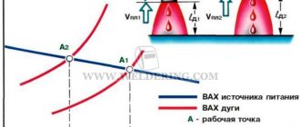
The amount of current is determined by the characteristics of a particular welding machine. In modern models, these indicators are indicated in the instructions. If for some reason you do not have instructions, then the current strength can be selected depending on the diameter of the electrode used. It is not allowed to use a current strength that is more suitable for a particular electrode. In this case, the electrode coating used to make the connection will be damaged and the arc will operate unstably. Using an electrode that is too large also has a bad effect on the process of joining metals: the current density decreases, the arc “runs away,” its length changes, and the weld does not turn out smooth and of high quality.
Extra options
Electric arc welding modes include not only basic, but also parameters that complement them. Such arc welding modes also influence the final weld.
Electrode stick out
Electrode extension is the distance from the end of the electrode to the surface of the metal part. It influences the welding process and the size of the resulting seam.
Increasing this parameter reduces the stability of the arc. The metal begins to spatter more strongly. The small overhang makes it difficult to observe the welding process. Spraying occurs on the nozzle.
Electrode coating thickness
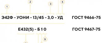
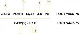
Manual arc welding modes include the characteristics of the electrodes, in particular, its coating, namely its thickness. This parameter is regulated by GOST 9466. Optimal coating requires its end size to be in the range of 0.5-2.5 mm. The use of current conductors with such a coating thickness ensures a durable seam that can withstand heavy loads.
Number of passes
The single-pass welding method involves welding in one layer. No oscillatory movements are made. It is used when welding parts of small thickness, when the seam width does not exceed 14-15 mm. At the same time, the magnitude of residual deformations decreases. For butt joints, especially when welding thick elements, several layers are used, and this method is called multi-pass.
A seam made in one pass has a larger pool. The advantages are the high productivity of the process and the cost-effectiveness of the method. Disadvantages include reduced weld ductility and too large heating zone. All seams in multi-pass welding are made with electrodes of the same size.
Electrode diameter
Welding modes depend on the type of electrode. The choice of its diameter depends on the thickness of the metal and the position of the seam. For any thickness, seams in a vertical position, horizontal and ceiling seams are welded only with a diameter of 4 mm. If the seam is multilayer, then a 3 or 4 mm electrode is used to weld the first seam, and subsequent seams are corrected using a larger electrode.
The table below shows the parameters of manual arc welding with the ratio of current, metal thickness and electrode diameter.
| Workpiece thickness, mm | 0,5 | 1-2 | 3 | 4-5 | 6-8 | 9-12 | 13-15 | 16 |
| Electrode thickness, mm | 1 | 1,5-2 | 3 | 3-4 | 4 | 4-5 | 5 | 6-8 |
| Current strength, A | 10-20 | 30-45 | 65-100 | 100-160 | 120-200 | 150-200 | 160-250 | 200-350 |
Content
- Current strength
- Arc Length (Arc Voltage)
- Welding speed
- Current polarity
- Ignition of the welding arc
When starting to work with manual arc welding, you need to choose the right welding mode. The quality of the weld is influenced by many parameters that are selected immediately before starting work:
- current strength;
- arc length;
- welding speed;
- current polarity;
- location of the seam in space;
- electrode diameter.
Mode depending on arc voltage
Arc voltage is related to its length. Typically the voltage is set in the range of 20-36 V. It increases as the arc length increases. The length of the arc can be short, medium and long.
Arc length is the distance from the tip of the electrode to the metal being welded. To make a quality connection, you need to ensure a stable arc size. It is believed that for beginners it is easier to maintain an average arc size. It is possible to make a high-quality seam with a short arc, but this requires experience and professionalism.
Influence on the choice of electrodes
The type of current also affects the choice of electrodes for welding. Thus, a unit operating on alternating current will be able to weld products only with electrodes specially designed for this purpose.
When working with such equipment, it is also possible to use universal consumables.
But this device cannot work with electrodes intended for use in direct current mode (UONII, for example). Note also that the inverter can cook with almost any consumables, but preference is usually given to universal rods.
Thus, the type of current, as a factor influencing welding procedures, determines the choice of a suitable apparatus and electrodes used in welding.
Welding speed for manual arc welding
Manual electric arc welding is characterized by the speed of its implementation. It affects the width of the seam. The faster the speed, the narrower the seam. When working slowly, the seam is wide. Transverse movements of the electrode during the joining process also affect the width and also the depth of the seam. Do not cook too quickly or too slowly. When working very quickly, spaces unfilled with metal will form, which can cause cracks. Working the electrode very slowly allows the molten metal to spread, which will make the product of poor quality. The movements of the electrode end can also be different (zigzags, herringbones).
Options for electrode direction when welding
Thus, choosing a manual arc welding mode is a set of actions aimed at finding the necessary parameters for connecting a specific product. If you are not a professional or even a complete beginner in this matter, then choosing the welding mode required for a particular product may not work the first time. But this is why there is practice, reference information, and instructions for reference, which indicate the parameters of manual arc welding depending on various indicators. It is worth noting that in each case all parameters are selected individually. You can select manual arc welding modes with coated electrodes yourself.
Features for vertical placement
Welding in a vertical position is more difficult compared to the horizontal version. Therefore, the choice of arc welding modes in this case is especially important.
How is the welding current adjusted in a vertical position? The first requirement relates to the arc - it must be short. The volume of the weld pool should not be large. To reduce it, electrodes with a small diameter should be used, and the current should be set 10-15% less than when welding is carried out in a horizontal position at the bottom.
Features of forward and reverse welding
The direct polar method is designed for:
- rolling installation from special steels using fusion method;
- non-consumable tungsten welding using surfacing wire;
- working with fluid materials;
- cutting workpieces using welding fixtures.
The thermal balance of the arc determines the nature of the distribution of thermal power.
If you accidentally change the pole, the working process with direct current will be delayed, the seam will become wide, and the rate of burning of consumables will increase. Reverse polarity is appropriate for carefully welding the workpiece, without allowing burns. This method is used for processing non-ferrous metals during flux welding.
Parameters of gas shielded welding mode
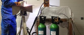
The welding mode is determined depending on the diameter of the wire and the strength of the welding current. Specialists increase gas consumption to improve gas protection, reduce welding speed, and use protective screens during work.
During welding, gas is supplied to the combustion zone. It displaces air from the arc combustion zone, thereby protecting the weld pool from oxygen and nitrogen from the air. The process is divided into welding in active (CO2, H2, O2, etc.) and inert (He, Ar, Ar+He, etc.) gases.
Consumable and non-consumable electrodes can be used in welding. To a greater extent, specialists work with consumable electrodes. This method is inexpensive when welding carbon and low-alloy steels, so it occupies one of the first places in terms of production volume among mechanized fusion welding methods. When using wire:
- with a diameter of up to 1 mm, and a current from 60 to 160 A, gas flow should be up to 8 liters per minute.
- with a diameter of up to 1.2 mm, and a current strength from 100 to 250 A, gas flow should be up to 9–12 liters per minute.
- with a diameter of up to 1.4 mm, and a current strength of 120 to 320 A, gas flow should be up to 12–15 liters per minute.
- with a diameter of up to 1.6 mm, and a current strength from 249 to 380 A, gas flow should be up to 15–18 liters per minute.
- with a diameter of up to 2 mm, and a current from 280 to 450 A, gas flow should be up to 18–20 liters per minute.
This is the average gas consumption when welding with a semi-automatic machine. There are also indirect factors that can affect additional gas consumption, for example, if welding takes place outside. In this case, the gas will quickly evaporate, thereby increasing its consumption.
Don’t forget about the quality of the gas itself, because if the gas is diluted, you simply won’t be able to keep the indicators normal; there will be excess consumption in any case.
Basic welding mode parameters
Welding mode refers to the main characteristics of the welding process, due to which welded joints of specified parameters, shapes and sizes are obtained. In this case, these characteristics can be: current density in the electrode, strength of the cooking current, speed of the cooking process, grade and granulation of flux, arc voltage, shielding gas consumption.
VT-metall offers services:
In order to determine which welding mode is required, it is necessary to determine the thickness and type of structure, as well as the composition of the metals. Based on the data received, the desired mode is set. There are two groups of factors on which the quality of welding depends: primary and secondary.
What criteria should you use to choose polarity?
When choosing the type of connection for a welding machine, you need to pay attention to a number of important criteria. This will prevent defects or excessive consumption of materials and ensure the required strength of the connection.
Sheet metal thickness
Parts whose thickness does not exceed 3 mm are often burned through. To weld such workpieces, a reverse-polar scheme is used, providing an anode thermal spot at the edge of the electrode. This approach is appropriate when processing non-ferrous, alloyed materials.
We recommend reading: How to make a potbelly stove for your garage yourself
Types of metals
The positive terminal is responsible for the final heating of the products and the holder. The cathode generates less heat than the anode. When machining refractory steels, it is better to use direct connection when the temperature reaches 4000 °C. For metals that change characteristics when overheated, connect the negative terminal. With direct-polar processing, the seam deepens; with “reverse” processing, it concentrates on the surface.
Types of electrodes
When choosing the brand of electrodes, take into account the type of current. Any variety is suitable for alternating voltage, since polarity does not play any role in this case. For varieties OK, OZS, MR, reverse connection is recommended. UONII and similar modifications are designed for a direct circuit. Manufacturers' recommendations are indicated on the packaging. Many welders prefer universal analogs to other options.
