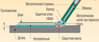
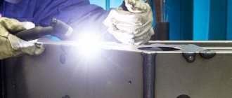
Any welder knows what a welding mode is, but not everyone can immediately tell how to set it up. This is not surprising, because the welding mode consists of many parameters, both basic and auxiliary. At the same time, they all play a very definite role and the quality of the welded joint largely depends on their correct settings.
In this article we will teach you how to make the correct choice and calculation of welding modes, and tell you what rules you need to follow to set up the machine. Let us clarify that in this material we will talk about the mode for manual arc welding (MAW), as the simplest and most common.
Welding mode parameters
Selecting a welding mode begins with parameters. There are basic and additional ones. Despite the names, they are all important and you need to be able to configure each parameter separately.
Main parameters:
- Welding current value.
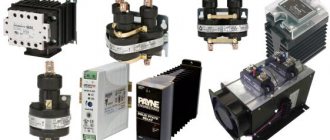
- Type of current (direct, alternating) and polarity of current (reverse, forward).
- Arc voltage value.
- Diameter of the electrode used.
- Welding speed.
- The number of passes during which the seam is fused.
Extra options:
- Method of cutting edges, their shape.
- The quality of metal preparation for welding.
- Type of electrode used, brand, coating, etc.
- Welding position (horizontal, vertical, ceiling, etc.)
- Welding angle
How an inexperienced welder can quickly select current parameters
To correctly set the welding current on the inverter, I suggest that novice welders use a simple table. It already indicates the current for welding with electrodes of various thicknesses. In this case, there is no need to read anything, it is enough just to know the thickness of the workpiece to be welded and the diameter of the electrode.
But all these are approximate calculations, because, in the end, the inverter may not produce the required current for some reason. This is mainly due to the fact that extension cords are used that are too large (20-30 meters long). You should be aware that when using long carriers, the welding current sags greatly.
The second point is related to low voltage in the electrical network. Sometimes welders complain that the electrode sticks to the metal without checking the voltage. Therefore, each time before welding, you need to check whether the voltage in the network is 220 Volts.
Welding calculation
To understand the essence, it would be nice to learn how to calculate the welding mode. We will teach you how to calculate manual arc welding modes, since this article is dedicated specifically to MAW. Naturally, the calculation for semi-automatic welding or any other method will be different. But within the framework of one article it is impossible to disclose all methods of calculation. So let's focus on RDS.
Welding current
The strength of the welding current is one of the most important parameters. After all, the higher the current, the faster the metal heats up and melts. And a high melting rate is not always beneficial, but we will talk about this later. Also, with a high current strength, overheating of the electrode and the part may occur, and burns will appear.
Afraid of making such mistakes, beginners often simply set the current to the minimum value, thereby complicating their task. As a result, they end up with unwelded seams and unstable combustion of the welding arc. In the worst case, the welding is simply interrupted as the arc goes out.
If you are a beginner welder, you can use the table below.
And for all practicing craftsmen, we suggest using the following formula for calculating welding current:
where K is the coefficient, dE is the diameter of the electrode, in millimeters.
The coefficient (“K”) depends on the diameter of the electrode (“dE”). To find out the coefficient, see the table below:
In addition to strength, it is important to correctly set the polarity and type of current. It is important to take into account the following features: if you set reverse polarity, the welding depth will increase by about 30-40%. And vice versa if you use straight polarity. The same thing happens when working with direct current, the penetration depth increases by about 10-15%. And with alternating current, on the contrary, it decreases.
Most experienced welders set the polarity and type of current at their own discretion. They observe the burning of the arc and its stability. And based on this, these values are already selected.
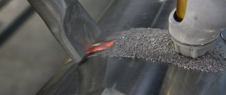
Welding speed
Calculation of welding speed does not have to be done using formulas. You can refer to regulatory documents, GOSTs. They specify the welding speed for each type of metal. You can safely rely on these values. A seam that has no unwelded areas or burns is considered ideal. There should be no influx. It is also believed that the width of a high-quality seam should be 2 times greater than the width of the electrode used.
It is also useful to understand what happens to the metal when the welding speed increases or decreases. If the speed is too high, then the metal simply will not heat up to the required temperature and the seams will not be welded. Which means they are fragile and short-lived. Well, if the speed is too low, then the metal will melt violently and sagging will form. In a word, strive for the golden mean.
Electrode diameter
With the diameter of the electrode, everything is more or less simple. The thicker the metal, the larger the diameter of the electrode. Below is a table with approximate values.
Name and write the formula that determines the strength of the welding current.
The strength of the welding current is determined by the formula: I=k∙Del or I=(20+6Del)Del, where k is a proportionality coefficient depending on the diameter and type of electrode, A/mm; Del—electrode diameter, mm.
Ticket number 4
Question
Welding torches (purpose, classification, design, marking, preparation for work, safety requirements).
The welding torch is used to mix flammable gas or flammable liquid vapor with oxygen and produce a welding flame. Welding torches are divided as follows: • according to the method of supplying combustible gas and oxygen to the mixing chamber - injection and non-injector; • by the type of combustible gas used - acetylene, for substitute gases, for liquid combustibles and hydrogen; • by purpose - universal (welding, cutting, soldering, surfacing) and specialized (performing one operation). An injection burner (Fig. 15) is a burner in which the supply of combustible gas to the mixing chamber is carried out due to its suction by a stream of oxygen flowing at high speed from the nozzle opening. This process of sucking gas of lower pressure with a stream of oxygen supplied at a higher pressure is called injection, and burners of this type are called injection burners.
Rice. 15. Design of an injection welding torch: 1 - mouthpiece; 2 — replaceable tip; 3 - mixing chamber; 4 — injector nozzle; 5 - oxygen valve; 6 — oxygen nipple; 7 - acetylene valve; 8 - acetylene nipple
For normal operation of injection burners, it is necessary that the oxygen pressure be 0.15-0.5 MPa, and the acetylene pressure is much lower - 0.001-0.12 MPa. Its operating principle is as follows. Oxygen from the cylinder under operating pressure through the nipple, tube and valve 5 enters the injector nozzle 4. Coming out of the injector nozzle at high speed, oxygen creates a vacuum in the acetylene channel, as a result of which acetylene, passing through nipple 6, tube and valve 7, is sucked in into mixing chamber 3. In this chamber, oxygen, mixing with flammable gas, forms a flammable mixture. The flammable mixture, exiting through the mouthpiece 1, is ignited and, burning, forms a welding flame. The supply of gases to the burner is regulated by oxygen valve 5 and acetylene valve 7, located on the burner body. Replaceable tips 2 are connected to the burner body with a union nut. A non-injector burner is a burner in which combustible gas and heating oxygen are supplied at approximately the same pressure of 0.05-0.1 MPa. They do not have an injector, which is replaced by a simple mixing nozzle that is screwed into the burner tip tube. Rules for handling burners:
1. Operation of faulty burners is not allowed, as this can lead to explosions and fires, as well as burns to the gas welder. 2. A working torch produces a normal and stable welding flame. 3. To check the burner injector, connect the hose from the oxygen reducer to the oxygen nipple, and the tip to the burner body. The tip is tightened with a wrench, the acetylene valve is opened and the required oxygen reducer is set
oxygen pressure according to the tip number. Let oxygen into the burner by opening the oxygen valve. Oxygen passing through the injector creates a vacuum in the acetylene channels and acetylene nipple, which can be detected by placing a finger on the acetylene nipple. If there is a vacuum, the finger will stick to the nipple. If there is no vacuum, it is necessary to close the oxygen valve, unscrew the tip, unscrew the injector and check whether its hole is clogged. If it becomes clogged, it must be cleaned, and the holes in the mixing chamber and mouthpiece must also be checked. After making sure that they are in good working order, repeat the suction (vacuum) test. 4. The amount of suction depends on the gap between the end of the injector and the entrance to the mixing chamber. If the gap is small, then the vacuum in the acetylene channels will be insufficient; in this case, the injector should be slightly unscrewed from the mixing chamber. 5. First, open the oxygen valve of the burner slightly, thereby creating a vacuum in the acetylene channels. Then open the acetylene valve and ignite the combustible mixture. 6. The flame is regulated with an acetylene valve with the oxygen valve fully open. 7. When there is a pop, first close the acetylene and then the oxygen valves. 8. Causes of popping noises: • severe overheating of the burner; • clogging of the burner mouthpiece; • if the flow rate of the combustible mixture becomes less than the speed of its combustion, the flame will penetrate into the mouthpiece channel and a back blow will occur. 9. In this case, the burner must be extinguished, cooled with water and the mouthpiece cleaned with a needle.
Ticket number 5
Question
Selecting the electrode diameter for manual arc welding
The main criterion when choosing the diameter of the electrode is the thickness of the welded edges. Also, when choosing a diameter, take into account the type of welded joint and the shape of the welded edges. The electrode diameters, depending on the thickness of the parts being welded, are presented in the table:
Thickness of welded edges, mm
| less than 2 | 3-5 | 6-8 | 9-12 | 13-15 | 16-20 | more than 20 | |
| Electrode diameter, mm | 2 | 3-4 | 4-5 | 5-6 | 6-7 | 7-8 | 8-10 |
When making fillet and T-welds, the diameter of the electrodes is selected based on the dimensions of the leg of the weld. When making seams with a 3-5mm leg, choose electrodes with a diameter of 3-4mm. If the weld leg is within 6-8mm, the electrode diameter is 4-5mm.
At the same time, it must be borne in mind that the use of electrodes with a diameter greater than 6 mm is limited due to their large mass. In addition, when using them, it is difficult to boil the root of the seam.
When making multi-layer seams, the best option would be to make the first layer with a small-diameter electrode (no more than 4 mm), for good penetration of the root of the seam in the depth of the groove. This applies equally to both butt welding and fillet welding.
What determines the current strength during welding?
The strength of the welding current depends not only on the diameter of the electrodes, although this criterion is one of the most important. The welding current parameters are also affected by the following nuances, which one way or another will have to be taken into account:
- Brand of electrodes;
- Spatial position of welding;
- Type of current;
- Welding current polarity;
- Number of layers of welded joint.
When welding a multilayer seam, the welder has to constantly adjust the current values. This is the only way to create a strong and permanent connection that will be highly reliable.
Also, the properties of the welding current largely depend on the spatial position in welding. When welding in a vertical position, the welding current is reduced, and in a horizontal position, on the contrary, it is increased, which makes it possible to achieve the required depth of metal penetration.
For ceiling welding, the maximum permissible electrode diameter is 4 mm.
How to choose the right current strength
The diameter of the electrodes must be selected based on the thickness of the metals being welded. The thicker the metals being welded, the larger the diameter of the electrodes should be.
Below in the table you can see what diameter of the electrodes corresponds to the thickness of the metals being welded.
For welded joints up to 5 mm wide, 3 mm electrodes are selected. In this case, the welding current corresponds to a value of 65-100 Amperes.
Welding of connections up to 8 mm is carried out with 4-5 mm electrodes. The current strength for this electrode diameter should correspond to a value of 120-200 Amperes.
Welding with 6-8 mm electrodes will require a current of 250-300 Amps. Such variations in welding current largely depend on the spatial position in welding.
There is also an unspoken rule among welders, according to which 30 Amps of welding current should be set on the machine per 1 mm of electrode. Thus, it is not difficult to calculate that for welding with a 2 mm electrode, the welding current should be 60 Amperes.
However, again, the values of the welding current can be adjusted depending on the spatial position in welding, as well as on some other features.