The grinding process is considered a very complex surface treatment process, which has its own specific features, which distinguish it from all other metal processing processes by cutting with tools made of metal alloys, solid carbide and with replaceable inserts that have the correct geometry.
The complexity of the grinding process and the variability of the cutting tool - the grinding wheel, in particular, create great difficulties in the practical and theoretical study of this finishing process of materials processing.
Metal grinding
What is metal grinding? This technology means its processing using abrasive material. This process is carried out using a special technique and is designed to change the texture of the surface, as well as its other characteristics. Grinding is applied to the outer and inner parts of the metal (flat or cylindrical).
Metal processing characteristics:
- grinding is the final stage of metal processing, which is carried out to create roughness;
- the technology is not suitable for radically changing the dimensions of the product;
- It is possible to obtain the required degree of roughness using modern equipment after processing the workpiece under high temperature.
In the process of metal grinding, a number of features are taken into account:
- cutting depth;
- possibility of cross feeding;
- product movement speed;
- wheel speed (depending on equipment characteristics and outer diameter).
Technology of processing workpieces on cylindrical grinding machines.
External round finishing of parts such as rotating bodies on centering machines can be carried out using longitudinal working strokes, plunge grinding or a combination.
When grinding using longitudinal working strokes, the part, rotating in fixed centers, performs longitudinal movement along its axis at a certain speed V, which is measured in mm/min. At the end of a double or each stroke, the abrasive wheel moves in a direction perpendicular to the axis of the workpiece to grind to the required depth.
This method is very often used for grinding objects with a cylindrical surface of considerable length. A grinding depth of no more than five hundredths per stroke of the machine table should be used. But it should be remembered that with fine grinding the size of the cut layer is much smaller.
Deep grinding as one of the types of grinding using longitudinal feed of the grinding wheel is used for processing hard short objects with material cutting up to 0.4 mm in one working stroke of the abrasive wheel. The allowance is removed using the conical part of the grinding wheel, and its cylindrical part cleans exclusively the working surface of the part.
Creep-feed grinding can be considered one of the varieties of plunge-cut grinding. Processing occurs at great depths of more than 5 mm, at low speeds of longitudinal movement from 100 to 300 mm per minute, in this way in one table stroke. Grinding refers to mechanical processing to remove defective layers of material from a part after welding, stamping, rolling, forging or casting.
Flat grinding is used for rough and finishing grinding of cylindrical workpieces. After finishing grinding, as opposed to non-finish grinding, it is necessary to maximize the desired shape and roughness parameters of the part being ground. Grinding takes place over one wide circle, the height of which is 1 or 1.5 mm greater than the length of the surface being sanded. The workpiece is rigidly fixed and longitudinal feeding is impossible; The lateral movement of the grinding wheel to the initially set grinding depth occurs without interruption or with a certain frequency. To obtain a surface with less shape deviation and roughness, the grinding wheel provides an additional axial oscillatory movement to the left and right of up to 3 mm.
This method of processing the workpiece has the following advantages over the grinding method using longitudinal movements:
o the movement of the feed wheel occurs continuously;
o You can grind workpieces using a profiled grinding wheel;
o 2 or 3 grinds. wheels can be applied on the machine spindle and simultaneously grind several parts of the workpiece.
Disadvantages of the embedding method:
o a large amount of heat is generated due to high efficiency;
o the wheel and workpiece heat up more than during normal grinding, so grinding should be carried out with intensive cooling;
o It is often necessary to correct a circle due to the rapid distortion of its geometric shape.
In the case of combined grinding, grinding is combined with longitudinal movements and immersion. This method is used when sanding long objects. First, one section of the shaft is ground with a lateral movement of the wheel feed, then with an adjacent section, etc. The edges of the segments overlap by 5 or 10 mm during grinding, but the surface is graded. Therefore, the partial constraint is removed at each location. The remaining layer of about 0.05 mm is removed with two or three longitudinal strokes at increased speed.
Devices for installing and securing wheels on cylindrical grinding machines are similar to the devices used for wheels of the same diameters on surface grinding machines.
The center at the back and the center at the front do not rotate. When processing a cylindrical surface of a workpiece, the axis of the wheel is parallel to the axis of the machine centers.
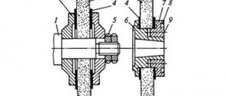
The center is installed in the spindle head of the machine. Rotation from the electric motor through the V-belt drive pulley is transmitted to the workpiece using a drive disk, pin and clamp. Special central holes are made at the ends of the workpiece (Fig.). The conical surfaces of these holes, when installing the workpiece, are connected to the conical surfaces in the center of the headstock and tailstock of the machine.
In some cases, the center holes are used with a protective groove or with a curved arch that forms a support cone. The advantages of central or spherical holes are their insensitivity to angular errors, better lubricant retention, reduced installation errors and greater machining accuracy. Workpieces with holes or undercuts on the front surface with a diameter of more than 15 mm are processed on an opaque substrate.
If the workpiece is subjected to heat treatment before grinding, the center holes must be cleaned of scale and dirt from grinding or grinding before installing the workpiece on the machine.
If there is a hole in the part, it may be based on spindle machining. According to the installation method, the pins are divided into center and hand; depending on the installation method - rigid and expandable.
Workpieces with precise base holes with a tolerance of 0.015 ... 0.03 mm or less are mounted on rigid mandrels with a small taper of 0.01 ... 0.015 mm per 100 mm or a press fit. When using less precise base holes, expandable mandrels are used. If the workpiece simultaneously rests on the surface and the hole, then mandrels with a sliding fit are used, on which one workpiece is installed or several workpieces are secured with a nut.
Spreaders also include mandrels with hydraulic or hydroplastic clamping. These mandrels can more easily accommodate inaccuracies in hole shapes, so the workpiece will be more accurately centered. The workpieces are mounted on such mandrels, deforming a thin-walled cylinder under uniform pressure from the inside. Liquid or plastic is used to create pressure.
Various straps, clamps, and chucks are used to transfer torque from the front of the machine to the workpieces.
When grinding objects whose length is 5-10 times greater than the diameter, the cutting force causes the object to deflect due to insufficient rigidity. At the same time, the grinding accuracy decreases, and oscillations and vibrations may occur in the LED technology system. In these cases, one or several permanent telescopes are used - additional supports for the workpiece.
In mass and mass production, adjustable telescopes with one or two washers are used. To produce radial (horizontal) and tangential (vertical) cutting elements. In the design, the remaining vertical position of the block mounted on the latch arm is fixed using an adjustment screw that moves in the rest of the housing. The position of the horizontal block mounted on the tip is adjusted using a screw. From the grinding workpiece around the wheel, it is necessary to adjust the position of the blocks, since the diameter of the polished surface decreases. The final position of the blocks depends on the diameter of the workpiece. When setting up a machine, the washers are set in accordance with the reference part or gauge using rings and, which limit the axial movement of the adjusting screws and. It is recommended to adjust the position of the washers using a screw, since the horizontal movement of the workpiece has the greatest impact on the processing accuracy.
.
Abrasive discs. The diamond pencil in the handle has a micrometric feed, which is performed by manual rotation of the handle. A diamond-free straightening pin can also be installed on copings. An automatic wheel dressing device is installed on the grinding blade body. The right device allows modification in one or two steps on a single or detailed copy. The correct device is activated by a control relay that counts the number of parts polished, or the operator presses a button for this purpose.
Measurement and measuring methods for circular grinding. In small-scale production, micrometers are widely used to measure the diameter of the grinding surface. Rigid and signal brackets are preferred in mass production. The fixed support has rigid or adjustable dimensions of the measuring jaws. The information in brackets is indicated: “pass” or “fail.” The indicator bracket shows the actual dimensions compared to the standard and allows the process to be monitored according to the remote limit.
Automatic disc grinders use automatic measuring tools and slave controllers.
Main types of grinding
Metal grinding is done using various methods. Technologies differ in the method of rotation (of a wheel or a workpiece), the speed of movement, as well as the side on which the grinder works (end, plane) and other factors. Main types of grinding:
- round;
- grinding of internal surfaces;
- gear grinding;
- centerless;
- flat.
Grinding methods are also classified according to the type of material used in the processing. To transfer the process to automatic mode, special machines or a built-in CNC unit are used, which reduces labor costs and ensures high quality products.
Cylindrical external grinding
Cylindrical grinding is the most popular method. It is not only external, but also internal. The circular method is carried out due to the synchronous rotation of the circle and the metal part. External grinding provides a cutting effect, and internal grinding provides uniform work.
Among the features of cylindrical grinding are:
- the abrasive wheel is a consumable material, it rotates around its own axis;
- the metal part rotates synchronously with the circle (this increases the efficiency of the process);
- Both longitudinal and transverse feeds are carried out (due to them, the depth of infeed changes and processing is ensured along the entire length).
This technology is suitable for processing cylindrical products, since when the circle comes into contact with a cylindrical product, the entire surface is processed.
Internal grinding
Internal grinding is similar to circular grinding, but differs in that the abrasive wheel is located inside the metal workpiece. Distinctive features of the technology:
- longitudinal and transverse feed can be carried out;
- the main rotation is provided by the abrasive wheel.
To increase the efficiency of the method, coolant is used. It is fed into the cutting zone.
Gear grinding
Gear grinding is a process that is carried out using gears. Hence the name. The complexity of the method lies in the fact that it is necessary to use technological equipment for grinding. Distinctive features of gear grinding:
- special machines are used for work;
- the circle is adjusted to the size of the tooth involute;
- the ring gear is processed.
The tooth surface is hardened, which can make machining the workpiece more difficult.
Centerless grinding
Centerless grinding is different in that the metal part is not fixed. The workpiece is placed between two grinding wheels that rotate. There is a stainless steel knife in the center, which eliminates the possibility of the product moving or jamming slightly.
Since the method involves the use of two grinding wheels at once, the process is much faster. Centerless grinding is carried out using special machines.
This technology is only possible in production workshops, and not at home.
Cylindrical grinding. Types of cylindrical grinding and grinding methods.
Finishing a product with a grinding wheel refers to the mechanical form of removing the material allowance. In this case, the top layer is removed using the physical properties of abrasive elements. Using this method, the outer surfaces of parts that have a cylindrical shape and, in some cases, different holes are processed.
In mechanical engineering, the following types of grinding are most often used in production: external round and internal round. External cylindrical grinding is suitable for processing cylindrical, as mentioned above, and products with a conical surface shape, which may have a flat surface or have “steps” on the surface. The workpiece, of course, is placed in the centers on the machine in order to avoid deterioration in the quality of the machined surface.
The abrasive tool must be selected depending on the type and condition of the material being processed, its size, and also depending on the shape of the surface being processed.
When the wheel is fed longitudinally, the material is removed in several passes with a minimum cutting depth into the material being processed. In some cases, material is removed in one pass with a cutting depth of up to 0.4 mm and a longitudinal feed of up to 6 mm/rev.
The main metal cutting is made at the front of the wheel. The rest of the tool provides the finishing. When removing large allowances, part of the circle is hidden step by step. The efficiency of deep grinding is 30% higher than that of the method with longitudinal feed, but the accuracy of the work is lower.
To improve accuracy, it is recommended that after removing a larger allowance, make several passes with longitudinal feed to clean the surface. Deep grinding is suitable for machining mostly hard parts.
Flat grinding allows you to process the surface along its entire length. This method can be used when the width of the surface to be treated does not exceed 200 mm.
Cross processing is considered the most productive method. In this case, the abrasive grain removes a fresh layer of metal, and processing occurs along the shortest path of the grinding wheel. A master working on a grinding machine and having good qualifications can process not only a cylindrical or conical surface, but also a shaped one.
Combined grinding is processing with transverse and longitudinal feed; this method can be used to process long hard objects.
Coarse grinding is carried out with large tolerances - from 3 to 5 mm, it can be used for pre-treatment of the surface with a tool.
Precision grinding is popular, so you can achieve 2-3 grade precision finishing. The removal of allowance is determined depending on the diameter of the part and the condition of the surface (up to 0.5 mm).
Fine grinding is easy to achieve with 1-2 accuracy classes. It is performed using a fine-grained wheel with a speed of more than 40 m/s, a rotation speed of parts up to 10 m/min and a plunge depth of up to 50 microns.
External circular grinding is mainly used for finishing and semi-finishing of parts on universal and special disc grinding machines. This way you can process a single object or work in serial and high-volume production.
It should be remembered that external grinding operations are easier to automate.
Internal cylindrical grinding is designed for machining cylindrical or conical internal surfaces. Grinding machines use the following methods for grinding holes: with longitudinal feed, countersinks with lateral feed or with additional movement of the wheel, with planetary movement of the grinding wheel.
The machining of long edges is very precise and leaves behind minimal roughness. The recessed version is used for machining blind and short holes. When grinding the inner conical surface of the hole, you need to turn the head using the handle. To work with the hole and the ends of parts from one installation, a rotary device with an end wheel is installed on the front swivel bracket. For internal grinding, the diameter of the grinding wheel is always smaller than the diameter of the hole in the element. Due to the small diameter, the circle wears out quickly.
Internal grinding can be performed with longitudinal feed of the tool (or directly) of the workpiece. You can also use the embedding method. All operations are the same as for external processing with longitudinal feed. Insertion and center machining methods are suitable for internal turning.
Passing internal holes requires the correct selection of equipment. To minimize vibration, which degrades quality and accelerates tool wear, a small spindle range is required.
To prevent through-holes from narrowing, the tool should be the same length on both sides. Blind holes are ground when the grinding tool is pulled out slightly.
Internal cylindrical grinding is suitable for precision machining of holes with a hardened surface or for machining parts made of particularly hard materials. Also, the circular grinding method is used to pass grooves, splines, and keyways.
To improve the surface finish, sanding should be performed at maximum speed.
Sanding flat surfaces
Flat grinding is one of the simplest technologies, since it is carried out only by the movement of abrasive nozzles, without rotation of other elements. This method is used for the manufacture of presses and other flat products. The technology used has its own characteristics:
- the metal workpiece is placed on a special table and securely fastened to it mechanically or using a magnet;
- the workpiece is mounted on an electromagnetic table or using machine tools;
- The main movement is taken over by abrasive attachments.
Thanks to this technology, it is possible to grind the most complex shapes. During operation, to increase efficiency, you can pour coolant into the contact point between the tool and the metal product.
Cylindrical external grinding
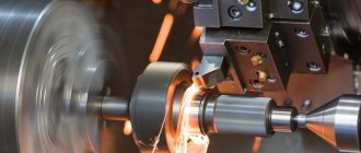
External cylindrical grinding usually refers to the process of grinding a workpiece while it is rotating on centers or a chuck (Fig. 1).
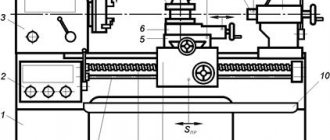
Cylindrical grinding machines are divided into universal and special. These machines grind cylindrical, conical, stepped and shaped surfaces.
There are two methods of processing workpieces on cylindrical grinding machines: grinding with longitudinal feed and plunge grinding.
Grinding with longitudinal feed (Fig. 2) is used when processing workpieces whose length significantly exceeds the width of the grinding wheel. One of the varieties of grinding with longitudinal feed is the deep-feed method (Fig. 3), in which grinding is carried out with a large feed to a depth t, a small longitudinal feed (S prod). The grinding depth is equal to the allowance left for processing, the wheel is fed immediately by this amount, and the workpiece receives a very slow longitudinal feed. When working in this way, the leading edge of the wheel quickly wears out, since it is subjected to maximum load and the wheel has to be adjusted more often. However, with this grinding method, a significant reduction in processing time is achieved by reducing the number of passes and distributing the load over a larger number of abrasive grains involved in cutting.
Plunge grinding is used in cases where the length of the surface to be ground is slightly less than or equal to the height of the wheel. This type of grinding is widely used in mass and large-scale production.
In order to speed up grinding operations on workpieces whose length significantly exceeds the height of the wheel, it is more rational to use a combined processing method (Fig. 4):
a) preliminary plunge-cut grinding with high transverse feed Spop by the amount of allowance and moving the wheel from position / to position //, ///, etc.;
b) final grinding with longitudinal feed S pr, providing the required roughness of the processing surface.
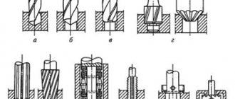
Machining the main (Fig. 5) and connecting rod (Fig. 6) crankshaft journals is one of the most difficult cylindrical grinding operations using the plunge method, since this involves combined grinding: circular grinding of the cylindrical surface of the journal and profile grinding of the fillets. There are special requirements for grinding wheels for processing crankshaft journals: on the one hand, the wheel must be able to withstand the adjusted radius of curvature (fillet), that is, be sufficiently hard, and on the other hand, it must not allow burns on the shaft journal, that is, be sufficiently hard. soft.
When grinding crankshaft journals, wheels made of white and titanium chromium electrocorundum with an outer diameter of 750-1100 mm and a height of 32-130 mm are used; 40 grit, hardness grades ST1-ST3 (for preliminary operation) and 25 grit, hardness grade SM1-C1 (for final operation).
Currently, special semi-automatic multi-circular machines are increasingly used for simultaneous grinding of three to six crankshaft journals with a set of grinding wheels (see Fig. 5). Despite the reduction in the cutting ability of each wheel by more than three times and the increase in machine time for grinding one journal by almost 2.5 times, labor productivity increases almost twice as compared to processing on single-circle machines with an increase in the geometric accuracy of the location of the journals relative to the central axis of the shaft .
For machines with multi-circle setup, increased requirements are placed on the complete set of wheels: the wheels in the set must be identical in cutting ability and durability. Balancing of sets of wheels is carried out outside the machines by displacing the heavy part of each wheel at a certain angle (360o/n, where n is the number of wheels in adjustment) relative to each other and thus balancing the entire set. The imbalance of the circles included in the kit must correspond to class 1 imbalance.
Similar results are achieved with combined grinding of workpieces with angular wheels, when processing is carried out by the periphery and the end of the wheel (Fig. 7).
The processing intensity is increased by combining grinding on several machined surfaces and eliminating the loss of auxiliary time for moving the wheel from one machined surface to another. Despite the intensification of processing, the load on individual abrasive grains does not increase, since the allowance is distributed over a larger number of them. At the same time, turning the wheel relative to the axis of the workpiece within 15-30°, when the speed difference on the working surfaces of the wheel does not exceed 5-8 m/s, increases the stability of the “machine-wheel-workpiece” system, increases its rigidity, and reduces the radial component cutting forces and wheel wear, which ultimately helps to improve the quality of processing, the durability of the wheels and their performance indicators.
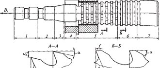
For external circular grinding of camshafts of internal combustion engines, PP type wheels with an outer diameter of 450-750 and a height of 20-40 mm on ceramic, bakelite or vulcanite bonds are used. To process workpieces of various diameters, cylindrical grinding is used simultaneously with several grinding wheels. For cylindrical grinding in centers, PP type wheels with an outer diameter of 250-1100 and a height of 20-75 mm are mainly used; for cylindrical grinding in centers with simultaneous trimming of the end side - PV type wheels with an outer diameter of 200-600 mm. For simultaneous processing of the workpiece along the outer diameter and flange, PVK type grinding wheels with a conical groove, which are a type of PV type grinding wheels, are used. The conical groove reduces heat and improves the conditions for grinding with the wheel end. For external grinding of workpieces, which simultaneously with processing along the diameter require trimming of protrusions on both sides (for example, when processing crankshaft cheeks), PVDK type wheels with an outer diameter of 750-1000 mm are used.
A powerful means of increasing the efficiency of the grinding process is to increase the operating speed of the grinding wheel to 60 m/s (high-speed grinding), 80 and even 100-120 m/s (high-speed grinding). Currently, the level of development of the abrasive industry allows the grinding process to be carried out in mechanical engineering at an operating speed of 60-80 m/s; increasing the working speed of the wheel to 60-80 m/s allows you to increase its durability by 1.5-3 times, reduce the roughness of the machined surface, reduce wheel wear by 1.5-2.0 times by reducing the average cut thickness and the corresponding her cutting forces. Reducing the cutting forces makes it possible to increase feeds in proportion to the increase in the operating speed of the wheel, that is, to intensify metal removal while keeping the quality parameters of the machined surfaces unchanged. At the same time, the increase in the cutting ability of an abrasive tool outpaces the increase in its wear resistance, helping to reduce the main grinding time and sharply increase the grinding coefficient. As a result of all this, with high-speed grinding, a significant reduction in the technological cost of grinding is observed.
Currently, PP type wheels with an outer diameter of up to 750 mm and a height of up to 100 mm are used for external grinding at centers.
Other metal grinding methods
There are also other, less common metal processing methods:
- Peeling – erasing the top layer if it has been damaged during use. After this, another sanding method must be used.
- Profiling is the most difficult technology, which involves working with a curve or broken line. This is the general name for gear grinding, thread grinding and spline grinding.
- Finishing – grinding, which is used to achieve shine and a polishing effect. This technology removes scratches and stains from the surface of the product.
Grinding
General information about sanding
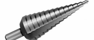
Grinding is one of the types of metal cutting processing. In Fig. Figure 10.1 shows typical parts processed on grinding machines. Among them are simple cylindrical rollers and complex engine crankshafts, splined rollers and bed guides, rings and long pipes, worms and gears, parts formed by flat surfaces, and parts whose surfaces have a complex spatial shape. Most often, external and internal cylindrical surfaces are processed during grinding.
Rice. 10.1. Typical parts processed on grinding machines
When grinding, the processing allowance is removed with abrasive tools - grinding wheels. Grinding wheel 1 (Fig. 10.2) is a porous body consisting of a large number of abrasive grains 7, connected to each other by a special substance 5, which is called a binder. The hard materials from which the grinding wheel grains are formed are called abrasives. The grinding process consists of the fact that the grinding wheel 1, when rotating, removes, while moving the part 8, a thin layer of metal (chips) with the tops of its abrasive grains located on the cutting surface.
Rice. 10.2. Scheme of interaction between the grinding wheel and the workpiece:
1 – grinding wheel; 2 – direction of rotation of the circle; 3 – cutting surface (periphery of the circle); 4 – direction of feed of the part; 5 – ligament; 6 – it’s time; 7 – grain; 8 – part to be ground
The number of abrasive grains located on the periphery of the grinding wheel is very large; it is measured on medium-sized circles in tens and hundreds of thousands of pieces. Therefore, when grinding, chips are removed by a huge number of randomly arranged cutting grains, also of irregular shape, which leads to very strong crushing of the chips and causes high energy consumption.
The elements of the cutting mode in cylindrical external grinding are the peripheral speed of the grinding wheel, depth of cut (transverse feed), longitudinal feed and rotation speed of the part.
Peripheral speed of the grinding wheel . In practice, wheel speeds from 20 to 60 m/s are used. The peripheral speed of the circle (m/s) can be determined by the formula:
where D is the diameter of the circle in mm;
n – number of revolutions per minute (rpm).
The peripheral speed of the workpiece is usually measured in meters per minute (m/min), since it is significantly less (usually 60–100 times) than the peripheral speed of the wheel. The speed of the part can be calculated using the formula:
where d is the diameter of the part in mm;
nd – number of revolutions of the part per minute.
The speed of rotation of the part is sometimes called circular feed.
Grinding depth . The amount of transverse movement of the grinding wheel in the direction perpendicular to the machined surface during one longitudinal stroke is called the depth of cut, or transverse feed. The cutting depth is the thickness of the metal layer removed in 1 pass. During cylindrical finishing grinding it ranges from 0.005 to 0.015 mm, and during rough grinding it ranges from 0.010–0.025 mm. Sometimes the grinding depth can be greater.
Longitudinal feed . Longitudinal feed during cylindrical grinding is the path traveled by a workpiece (or wheel) in a direction parallel to the axis of rotation of the wheel in 1 minute or during 1 revolution of the workpiece being ground. Therefore, longitudinal feed can be measured in the following units: in fractions of the height (width) of the circle per 1 revolution of the part; in millimeters per 1 revolution of the part (mm/rev); in millimeters per 1 minute (mm/min). The amount of longitudinal feed during cylindrical grinding depends on the type of grinding: for rough grinding of parts made of any materials with a diameter of less than 20 mm, the feed is taken from 0.3 to 0.5 N (where H is the height of the grinding wheel); when rough grinding parts of larger diameter made of hardened steel - up to 0.7N; for parts made of unhardened steel - up to 0.75N and for parts made of cast iron - up to 0.85N. When finishing grinding, the feed is (0.2–0.3) N, regardless of the material and diameter of the workpiece.
Cooling during grinding . To remove generated heat from the cutting zone, reduce friction and remove grinding waste, abundant cooling with various coolants is used.
Cast iron and copper alloys can be ground without cooling, and the machines must be equipped with vacuum cleaners that remove abrasive dust. The coolant, by washing away abrasive metal dust, helps improve the quality of the ground surface.
In mechanical engineering, the following types of grinding are most often used: external round, internal round, flat and centerless.
Cylindrical external grinding
In external cylindrical grinding, the workpiece is mounted in centers or secured in a chuck. There are grinding with longitudinal feed, deep grinding and plunge grinding.
To carry out the grinding process, it is necessary that the workpiece and the abrasive tool have appropriate relative movements.
When external cylindrical grinding with longitudinal feed requires the following movements (Fig. 10.3a): rotation of the grinding wheel is the main cutting movement; rotation of the part around its axis - circular feed of the part; rectilinear reciprocating movement of the part (or grinding wheel) along its axis - longitudinal feed; transverse movement of the grinding wheel onto the part (or parts per wheel) - transverse feed, or feed to the grinding depth. When grinding with longitudinal feed, transverse feed is carried out periodically, at the end of each double or single stroke of the table. When deep grinding, the allowance is removed in one pass, and the longitudinal feed is chosen to be very small. When performing circular external plunge grinding (Fig. 10.3b), the height of the grinding wheel used is taken equal to or slightly greater than the length of the part. Therefore, there is no need for longitudinal feed here. Transverse feed, unlike the first method, is carried out continuously throughout the entire grinding process. Thus, to perform external plunge grinding, the following movements are necessary: rotation of the grinding wheel, rotation of the part around its axis (or its circular feed) and continuous transverse feed of the grinding wheel.
Rice. 10.3. Schemes of the main types of grinding:
a – round external with longitudinal feed; b – round external plunge; c – round internal with longitudinal feed; g – external centerless; d – internal centerless; e – flat periphery of the circle; g – flat end of the circle
Cylindrical internal grinding
This type of grinding includes grinding with longitudinal feed and plunge grinding.
For circular internal grinding with longitudinal feed (Fig. 10.3c), the same movements are required as for circular external grinding with longitudinal feed: rotation of the grinding wheel, circular feed of the part, longitudinal feed of the part or wheel, transverse feed of the wheel.
Centerless grinding
With centerless grinding, the cutting process is carried out with a grinding wheel in the same way as on conventional center grinding machines. The peculiarity of this process is determined by the specifics of fastening and feeding the part. With centerless external grinding (Fig. 10.3 d), the part to be ground is placed on a support knife between the working circles (on the left) and the feed or driving circle (on the right). To carry out the centerless grinding process, the following movements are required: rotation of the grinding and feed wheels, circular and longitudinal feed of the part. The rotation of the feed wheel imparts rotation and longitudinal feed to the grinded part. To obtain longitudinal feed of the part, the axis of the driving circle is set at a small angle α to the axis of the working circle.
Cylindrical internal centerless grinding (Fig. 10.3e) is similar to external grinding and is carried out without securing the part being ground. During the grinding process, the workpiece is supported by 3 support rollers.
Pages:
- |
- |
- |
- |
- |
- |
- |
- |
- |
- |
- |
- |
- |
- |
- |
- |
- |
- |
- |
- |
- |
- |
- |
- |
- |
- |
- |
- |
- |
- |
- |
- |
- |
- |
- |
- |
- |
- |
- |
- |
- |
- |
- |
- |
- |
- |
- |
- |
- |
- |
- |
- |
- |
- |
- |
- |
- |
- |
- |
- |
- |
- |
- |
- |
- |
- |
- |
- |
- |
- |
- |
- |
- |
- |
- |
- |
- |
- |
- |
- |
- |
- |
- |
- |
- |
- |
- |
- |
- |
- |
- |
Processing parts before grinding
Metal grinding is the final stage of processing, and it requires preliminary preparation. Before the process, it is necessary to process metal parts in several stages:
- Rough turning of the workpiece. At the first stage, the workpiece is given the required shape and dimensions, taking into account the allowance.
- Finish turning of metal. The workpiece is processed to the required size.
- Milling. This technology involves removing the workpiece mechanically. Milling is most often carried out on housing parts and gears.
- Metal processing under high temperature. The workpiece is hardened in order to significantly increase the hardness and strength of the surface. Annealing and tempering reduces the fragility of the product. In some cases, during the heat treatment process, certain chemicals are applied to the surface layer.
The Cherepovets metal structures plant has been working for you for more than 55 years. We design products, then manufacture them in our own workshops and deliver them throughout Russia. To order, call 8 or order a call on the website.
Detailed description of the grinding process
Cylindrical grinding involves several step-by-step steps.
Basic grinding methods
Grinding with longitudinal strokes
The processed blank, after being securely fastened by rotation, moves along its own axis at a specific speed V (millimeters per minute). At the end of double or all working strokes, the wheel being processed moves in the direction that is located at right angles to the axis of the workpiece to a predetermined grinding depth. Most often, this technique is used to process various blanks that have a cylindrical surface shape. The depth is selected within values that do not exceed five hundredths of a millimeter per stroke. Finishing is performed at lower values.
Deep
Grinding with a wheel that is fed longitudinally. The method is relevant for hard materials with allowance removal of up to four tenths of a mm in just one pass. The main work is performed by the conical element of the circle, and the cylindrical element performs the cleaning. In general, this method can be considered from the point of view of rough grinding. Depths are more than five mm, longitudinal feed rates vary from one hundred to three hundred (mm per minute) per single stroke. The stripping method refers to the removal from the plane of the blank of an unusable layer that has a number of defects after the process of casting, rolling, and so on.
Mortise
Used for roughing and finishing methods. The latter method, unlike the first, is necessary to give the desired geometric shapes, as well as the level of roughness of the blank plane itself. Grinding is carried out with a single circle of large width; its height is one...one and a half mm greater than the length of the grinding area. The blank is without movement. The circle is fed periodically or continuously. To achieve a small deviation in shape and roughness, the circle is given an oscillatory movement (up to three mm) in two directions (l/r)
Advantages:
- Continuous feed of the circle.
- Working with shaped materials using a profiled wheel.
- Installing up to three circles on the spindle simultaneously, thereby processing several areas at once.
Minuses:
- Generating excessive heat.
- Requires more frequent cooling with colossal productivity.
- Frequent straightening of the circle, as the given geometric shape is quickly lost.
Combined method
Combination of machining with longitudinal strokes and insertion. Let's use this method for long blank materials. At the initial stage, one part is ground with a transverse feed, then the adjacent section. In this case, the edges of two and subsequent sections overlap each other by five...ten mm, thereby resulting in a stepped geometry. For this reason, only part of the allowance is removed, and the rest (two...eight hundredths of mm) is eliminated by two or three longitudinal movements, which have a higher speed.