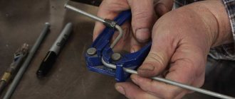
Pipe rolling machine
When rolling long pipes on a machine, the center of movement is shifted. Due to this displacement, a curve is formed between the rollers. One roller presses from the inside of the radial contour, and the other two form the external contour of the future product.
Drawing of a pipe bender for pulling profile pipes. All dimensions of parts required for manufacturing are indicated:
Structurally, such a device is made on a strong support made of channel. The lower rollers are located in bearings. Usually the distance between them does not change (there are versions of the machine where, by changing the location of the lower rollers, a different rolling radius is created).
The top roller is located on top. It can be moved in height. By moving the supporting part downward along the thread, significant forces can be developed. They will act on the pipe during the rolling process.
To perform rolling, additional pulling forces must be applied in the longitudinal direction. A handle is installed for this purpose. By rotating it, you can make the pipe move in one direction or another.
For self-production, you can go a different route. The walls of the device are cut out of a sheet 2...4 mm thick, where the rollers are installed.
Simplified pipe bender design:
The most difficult thing is to make the sidewalls, inside of which are located:
- Support shafts – 2 pcs.
- A pressure roller located on a suitable device.
- A handle that allows you to roll a profile pipe.
Industrial machines are made with manual or electric drive. When manufacturing an electrified machine, the possibility of reverse must be provided. Then you can roll, forcing the length to move in both directions.
offers pipe rolling mills. The pipe rolling mill is an automatic line for the production of welded pipes of round square or rectangular cross-section from steel strip/strip. The quality of pipes produced on our equipment meets the requirements of GOST 8645-68, 10704-91, 3262-75. The scope is very diverse (mechanical engineering, gas and oil industry, housing and communal services, construction of urban and industrial buildings, etc.)
Part of the equipment:
- Loading cart
- Hydraulic unwinder
- The right car
- Hydraulic strip end trimming device
- Welding machine for roll enlargement
- Horizontal loop storage
- Forming stand group
- High Frequency Welding Machine
- Deburring
- Cooling installation
- Calibration group of stands
- flying saw
- Outgoing roller conveyor
- Pipe packaging pockets
Loading cart
Loading trolley with electric drive, with hydraulic lifting and supply of strip to the area where it is captured by the unwinder.
Unwinder
An unwinder with an electric drive is designed for unwinding and feeding the strip into a straightening machine.
The right car
Leveling machine equipped with hydraulic mechanism, leveling rollers and feed rollers. Designed for straightening strips.
Hydraulic strip end trimming device
Serves for cutting defective ends of strips for further enlargement of rolls using welding.
Butt welding machine
Serves for welding the ends of rolls, which allows for continuous rolling of pipes.
Horizontal loop storage
A horizontal loop storage device in the form of a drum, equipped with a hydraulic strip gripper and a system of guides and transport rollers, is designed to accumulate strip and feed the strip into the forming group of stands.
Forming stand group
The group consists of several stands in which the rolls are calibrated in such a way that the strip is sequentially formed into a pipe blank.
High Frequency Welding Machine
Performs welding of pipes using the high-frequency method, at the same time removing external flash.
Cooling installation
Cools the pipe after welding. Type – water shower.
Calibration group of stands
The group consists of several stands with a roll caliber shape that produces the final calibration of the geometric shape of the pipe, bringing the pipe shape to GOST requirements.
flying saw
Serves for automatic adjustment of the cut of a continuous pipe into measuring pipes.
Outgoing roller conveyor
The drive roller conveyor serves to remove the finished pipe from the mill.
Pipe packaging pockets
Finished pipes are placed in bags, packaged, weighed and sent to the finished product warehouse
Additionally, the mill can be equipped with the following components:
- Eddy current weld quality control system. Control equipment is built into the line immediately before the calibration group of stands and monitors the quality of the weld. During inspection, the system marks defective areas so that later, after the cutting section, the pipes are stored in a separate pocket.
- Installation for hydrotesting. The installation is designed for testing round pipes by creating increased hydrostatic pressure in the pipe.
Finished products
To select the necessary equipment and determine its cost, fill out the questionnaire
Making a pipe bender with your own hands
The simplest pipe bender is relatively easy to make. Need to purchase:
- bearings No. 206;
- bearing housings;
- shafts Ø 35 mm made of hardened steel HRC 40...45 (suitable for the internal size of the bearings);
- bicycle sprockets of the same diameter;
- bicycle pedal;
- lead screw with nut;
- channel No. 8;
- channel No. 6;
- M8 bolts with nuts;
- strip 40 mm, thickness 4 mm.
To make it you need to use:
- Electric drill.
- File.
- Angle grinder with cutting and cleaning discs.
- Welding machine.
- Set of wrenches.
Step-by-step manufacturing of the machine
Having prepared a set of components, we begin manufacturing.
General view of the machine. It is installed on timber 100·50 mm.
All details are displayed in a visible place. The performance of the bearings and lead screw is preliminarily checked.
Blanks are cut from channels. A vertical stand is welded from them, installed perpendicular to the supporting channel.
A hole is drilled for the lead screw. A nut is welded to it. Then screw in the screw. A cross member is welded on top; it will be needed to move the screw along the thread.
Bearings move along the support channel. They are pre-installed in the housings. Shafts are inserted inside. Chain sprockets are welded to one of the ends.
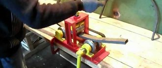
A bicycle pedal is welded to one support shaft. By rotating it in one direction or another, you can force the pipe to move in the desired direction.
Having manufactured the clamping mechanism, the location of all elements is checked. They try to install them according to the drawing presented earlier.
Having installed the parts in place, they are welded. Now it’s time to check the functionality of the device.
Place the pipe and roll it in both directions. There is no pressure from above yet; we are checking how easily the pipe moves.
By turning the screw, press the pressure roller down and push the pipe. By moving the pressure roller, roll the pipe. After each pass, move the roller down. Periodically remove the part and compare it with the template.
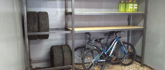
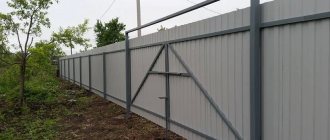
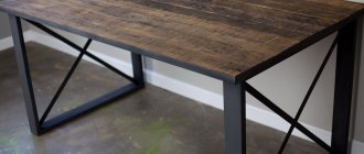
Having manufactured the machine, you can begin to manufacture greenhouses and greenhouses, which are based on profile pipes. Below are examples and information on how to make such structures.
Video: homemade pipe bender for a profile pipe.
Pipe production. Pipe production equipment
Units for continuous furnace pipe welding.
Using units for continuous furnace butt welding of pipes, gas pipes with a diameter of 6 to 114 mm with a wall thickness of 1.8-5 mm are produced, used mainly in industrial and municipal construction for gas, air and water pipelines, central heating systems, as well as in structural quality.
The initial blank for the production of pipes by continuous furnace welding is hot-rolled strip in rolls of low-carbon open-hearth or converter steel, having rolled or cut edges. The first is obtained on a strip mill, the second - by cutting a wide strip on disk shears.
In furnace welding, the entire strip is heated in a continuous furnace, continuously shaped and welded, which is caused by compression of the edges of the strip, heated to a temperature close to the melting point of the metal. The method of continuous furnace welding allows the process to be carried out at sufficiently high speeds, to obtain a tight seam on pipes with minimal internal flash, and also to use the heat of heating the metal for forming and welding to reduce pipes under tension. The inclusion of reduction-stretching mills in continuous furnace pipe welding units made it possible not only to increase the productivity of continuous furnace welding shops, but also to expand the range and improve the quality of produced pipes.
The technological scheme for the production of pipes using continuous furnace pipe welding units includes the following technological operations: preparing the strip (unwinding the roll, straightening, accumulating metal in the loop former and joining the rolls), heating the strip to a temperature of 1350-1400°C (the edges are heated by 100-150 ° above the middle of the strip), forming and welding of pipes, reducing and calibrating, cooling and a complex of finishing operations and, if necessary, galvanizing of pipes.
Strip rolls are loaded into the receiving device of the mill, and from there they are fed to the decoiler. The strip coming out of the unwinder successively goes through straightening, butt welding of the ends of the previous and subsequent rolls, and deburring.
The continuity of the welding process during the joining of the ends of the strip is ensured by the presence of a primary loop between the pulling rollers installed behind the joint welding machine and the loop former.
The tape is heated when moving at welding speed in tunnel-type furnaces. On continuous furnace welding units, strip forming is usually carried out in four-stand forming and welding mills with an individual drive for each stand. The first stand with vertical rolls is a forming stand, the second with horizontal rolls is a welding stand. The remaining two stands are crimp stands.
The cantilever rolls of the vertical and horizontal stands are rotated by an electric motor through a gearbox - a gear cage; the drive of the vertical rolls is installed on a platform raised above the workshop floor. The rolls are placed in a special replaceable cassette.
Forming of the strip begins before it comes into contact with the rolls of the first stand of the forming mill. The gauge axis of the first stand is 12-20 mm below the gauge axis of the second stand. Due to this, the edges between the stands continue to approach each other and are finally connected in the second stand. In the remaining stands of the forming and welding mill, the reduction is 68%.
To remove scale and slag from the edges of the strip, as well as to increase the temperature of the edges, they are blown twice with compressed air or oxygen before welding. The temperature of the edges after blowing is 1475-1500°C.
After welding, the pipes are subjected to reduction with tension on multi-stand mills of various designs. Most often, two-roll, twenty-stand mills with individual drives are used. The design of the stands is similar to the stands of a forming and welding mill. Two- and three-roll mills with differential hydraulic drive are also used.
A calibrating mill is installed behind the reduction-stretching mill at a distance of 10-15 m from it. The pipe is transported between the mills by a roller table, and as it moves along the roller table it is cooled. Cooling the pipe by approximately 100°C increases profile stability and helps produce a more accurate profile.
The calibrating mill consists of three stands with individual drives. The first and last stands have horizontal rolls, the middle stand has vertical rolls. The design of the stands is similar to the stands of a reduction mill. From the last stand of the sizing mill, a synchronization unit is driven that controls the drive of the flying saw, which is used to cut pipes on the fly into measured lengths.
Pipe-electric welding units
Pipe electric welding units are high-performance installations operating at welding speeds up to 1.65-2.0 m/s (100-120 m/min). High welding speeds are achieved through the use of a continuous process for producing pipes from welded individual rolls of strip, forming an “endless” strip, and through the use of new welding methods.
Electric welding by various methods is widely used for the production of water, gas, oil and structural pipes with a diameter of 6 to 530 mm.
The starting material is strip, as well as cold-rolled and hot-rolled strip in rolls.
The roll is placed in the unwinder, after which its front end is inserted into a straightening machine, in which the strip is straightened. After straightening, the tape is fed to the scissors, where the front and rear ends are cut off, and then the tape goes to the butt welding machine.
To ensure high-quality joining of rolls on a butt welding machine, the ends of the tape must be cut exactly at an angle of 90°. The butt welding machine is adjusted to each tape size. The upper jaws are adjusted in height taking into account the thickness of the tape; The lower jaws are installed strictly in one plane and checked with a ruler.
After flash butt welding, the flash formed on the weld is removed with a deburring tool. The tape is clamped in the blocks of the movable carriage, after which the weld is pulled between the knives.
The endless strip is then fed into edge trimmers to be cut to a specific width. The end of the tape is captured by feed rollers installed in front of the shears and fed into the shears. After this, the tape is moved using scissor knives, and the rollers are turned off. When the strip enters the forming mill, the shear drive is switched off and it is pulled through the mill rolls. If, after the scissors, the tape enters the looper, it is pulled through special pulling rollers.
From the looper, the tape enters a continuous forming mill, consisting of driven horizontal and non-driven vertical rolls.
The formed pipe blank then enters the welding mill, where its edges are welded.
The welded pipe enters the deburring cage. The burr formed on the outer surface of the pipe is removed while hot with a cutter. The cutter setting should be such as to remove only burrs, preventing the formation of a platform at the weld site that would take the pipe out of tolerance for wall thickness.
Before the sizing or reduction mill, the welded pipe is cooled in a refrigerator with running water. In the sizing mill, the pipe is calibrated by its outer diameter in order to obtain the correct geometric shape and required dimensions.
From the last stand of the sizing mill, a synchronization unit is driven that controls the drive of the flying saw, which is used to cut pipes on the fly into measured lengths.
All finishing equipment is installed in line with the mill and connected to each other by roller tables, ensuring pipe transportation without the participation of overhead cranes.
Finished pipes are transported via roller tables or gratings to the finished product warehouse.