Ordinary people, which includes me, divide metal detector coils into 2 types - Mono and DD. Metal detector manufacturers are cutting thinner...
Why does the DD coil have this designation? Do you know the difference between Mono and Concentric coils? And if you do not have a pulse metal detector, then what you call a mono coil is more correctly considered concentric. Let's look at the difference between search coils and how this affects practical search.
Mini educational program... A metal detector coil most often consists of 2 components - a transmitting loop (Transmit Coil, TX) and a receiving loop (Receive Coil, RX). The first generates an electromagnetic field, the second monitors changes in this field (when a metal object gets under the coil, the field is deformed, these distortions give the metal detector a reason to tell you “dig!”).
If the transmitting loop is larger, the generated field will also be larger. Hence the dependence of the coil size and detection depth. A small nuance, high mineralization of the soil can introduce interference into the field, and this is part of the search environment.
Concentric coil
A concentric coil is most often what we call a Mono coil (for example on the Garrett ACE 250). But just a mono coil is a type of Concentric.
The peculiarity of a concentric coil is that the transmitting and receiving loops are spaced as far apart as possible. This allows you to create a symmetrical field (hence the accuracy of the pipoint), slightly better separation of adjacent finds with one sweep (from the conical shape of the field).
Concentric coils are designed to cover the full range of existing finds. Logical positioning - universal coils. They are susceptible to the influence of high mineralization of the soil; when increased, the coil loses depth.
Metal detectors, also known as metal detectors: operating principles and diagrams.
BFO metal detectors based on beats, metal detectors based on the principle of an electronic frequency meter, pulse metal detectors. Optimal radiation frequencies.A metal detector, also known as a metal detector , is an electronic device that allows you to detect metal objects in a neutral or weakly conductive environment due to the presence of electrical conductivity in these objects. So, what should this weakly conducting medium be like if we know that almost all materials conduct current to one degree or another? Well, at least several orders of magnitude lower than the conductivity of metals. Of course, we won’t find a golden cigarette case inside a tank sunk in a swamp, but some piece of iron in the ground, water, wall, wood, suitcase, in someone’s body, in the end, etc. and so on. - this is please, welcome to the metal detector examination.
Now - on what principle do metal detectors (metal detectors) work ? There are several operating principles:
Metal detector based on the “transmission-reception” principle with a continuous signal.
Everything here is clear and corresponds to the name: The transmitting coil is continuously fired by an alternating electromagnetic field at the desired metal object that is nearby. Under the influence of this field, electric currents arise in the object acting as a target, which, in turn, create their own magnetic field, with a direction opposite to the magnetic field of the transmitter. The receiving coil registers the signal reflected (or, as they say, re-emitted) from a metal object (target). This signal is then amplified and processed electronically, having previously separated it from the more powerful transmitter signal. The larger the object and the closer it is located to the coils, the higher the amplitude of the re-emitted signal will be. A device of this type requires the presence of at least two coils, one of which is transmitting and the other is receiving. Moreover, it is necessary to take care of choosing the relative arrangement of the coils in such a way that the magnetic field of the emitting coil, in the absence of foreign metal objects, induces a minimal (ideally zero) signal in the receiving coil (or in the system of receiving coils).
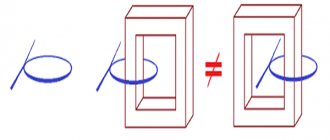
Fig.1
There are various options for the relative arrangement of the coils, in which there is no direct signal transmission from one coil to another. The main ones are: coils with perpendicular axes (Fig. 1, a and b), as well as the option of placing a receiving coil, twisted in the shape of a figure eight, inside the transmitting coil (Fig. 1 c).
Since the design of these types of metal detectors is quite complex, since it implies the presence of separate coils for reception and transmission, it has not found widespread use in amateur radio practice.
Metal detectors built on the beat principle, or so-called BFO metal detectors, are a completely different matter
The principle of operation of a beat metal detector is to register the frequency difference from two generators, one of which is stable in frequency, and the other contains a sensor - a search coil inductor in its frequency-setting circuit. The device is adjusted in such a way that, in the absence of metal near the sensor, the frequencies of the two generators coincide or are very close in value. The presence of metal near the sensor leads to a change in the inductance of the sensor and, as a consequence, to a change in the frequency of the corresponding generator. This change will lead to a change in the difference frequency of the two generators, which is allocated by a special device (mixer), the inputs of which are supplied with signals from both generators, and the difference frequency, called the beat frequency, is allocated at the output. The frequency difference can be recorded in a variety of ways, from the simplest, when the difference frequency signal is listened to on headphones, to digital methods of frequency measurement. The operating frequency ranges of BFO metal detectors are 40-500 kHz. If there is no metal in the field of the search coil, the difference frequency should be within 500...1000 Hz.
As an example, I will give a diagram of the simplest compact metal detector on the K175LE5 microcircuit (Source V. Yavorsky. Metal detector on the K176LE5. // Radio, 1999, No. 8, p. 65).
Fig.2
The circuit contains two oscillators (reference and search). The search generator is assembled on elements DD1.1, DD1.2, and the reference generator is assembled on elements DD1.3 and DD1.4. Variable resistor R2 smoothly changes the frequency of the search generator in the frequency range set by trimming resistor R1. The frequency of the generator on elements DD1.3 and DD1.4 depends on the parameters of the oscillatory circuit L1, C2. Signals from both generators are supplied through capacitors C3 and C4 to a detector made using diodes VD1 and VD2. The load of the detector is the BF1 headphones, on which the difference signal is isolated in the form of a low-frequency component, which is converted by the headphones into sound. A capacitor C5 is connected in parallel with the headphones, which shunts them at a high frequency. When the search coil L1 approaches a metal object, the frequency of the generator on elements DD1.3, DD1.4 changes, as a result the tone of the sound in the headphones changes. This feature is used to determine whether a metal object is in the search area.
Fig.3
Coil L1 is placed in a ring with a diameter of 200 mm, bent from a copper or aluminum tube with an internal diameter of 8 mm. There should be a small insulated gap between the ends of the tube so that there is no short-circuited turn. The coil is wound with PELSHO 0.5 wire. It is necessary to stretch the maximum number of turns through the tube in any way: the more, the better.
Despite the prevailing opinion that BFO metal detectors do not have a clear selectivity of different types of metals, with some experience, this type of device can still be selected by analyzing and filtering signals by ear.
In theory, the sensitivity of BFO metal detectors should be at the same level as that of devices built on the “transmit-receive” principle. However, there is a significant problem that reduces the sensitivity of devices of this type. The problem is that two oscillators tuned to very close frequencies tend to synchronize with each other. And this, in turn, does not make it possible to work at low initial difference frequencies, at which the ear has maximum sensitivity to changes in the tone of the sound signal.
And then, with a slight movement of the hand, the BFO metal detector turns into a Metal Detector operating on the principle of an electronic frequency meter.
An electronic metal detector built on this principle is an undoubted relative of a “beating” device, but unlike it, it contains one generator with a frequency-setting search coil, and the change in frequency is recorded by an electronic device operating on the principle of a frequency meter. In addition to increasing sensitivity, devices of this class also have the ability to evaluate the sign of the frequency increment, and, accordingly, the ability to select ferrous/non-ferrous metals.
The simplest implementation of such a design without a metal type selector was proposed by M.V. Adamenko. in the book "Metal Detectors".
Fig.4
The proposed design is a device based on the principle of analyzing the frequency deviation of the reference oscillator under the influence of metal objects that fall within the range of the search coil. The main distinctive features of this device can be considered an interesting circuit design of the analyzer, made on a Q1 quartz element, as well as the use of a pointer device as an indicator.
The basis of the circuit of the metal detector in question (Fig. 4) is a measuring generator, a buffer cascade, an analyzer, a detector of high-frequency vibrations and an indicator device. The oscillatory circuit of the high-frequency generator, made on transistor T1, consists of coil L1 and capacitors C3-C6. The operating frequency of the HF generator depends on the deviation of the inductance of the L1 coil, which is also a search coil, as well as on changes in the capacitances of the tuning (C4) and regulating (C3) capacitors. In the absence of metal objects in the range of the L1 coil, the frequency of oscillations excited in the RF generator should be equal to the frequency of the quartz element Q1, that is, in this case, 1 MHz. Once a metal object is in the range of search coil L1, its inductance will change. This will lead to a change in the oscillation frequency of the RF generator. Next, the RF signal is fed to a buffer stage, which ensures matching of the generator with subsequent circuits. An emitter follower made on transistor T2 is used as a buffer stage. From the output of the emitter follower, the RF signal through the adjusting resistor R7 and quartz Q1 is supplied to a detector made on diode D2. Due to the high quality factor of quartz, the slightest frequency shift of the measuring generator will lead to a decrease in the impedance of the quartz element. As a result, a signal is received at the input of the DC amplifier (base of transistor T3), a change in the amplitude of which provides a corresponding deflection of the needle of the indicator device. The load of the UPT, made on transistor T3, is a pointer device with a total deviation current of 1 mA. When switch S2 is closed, an audio signal generator based on transistor T4 is switched on in the load circuit.
The L1 search coil is a ring frame made from a piece of cable with an outer diameter of 8-10 mm (for example, RK-50 cable). The central core of the cable should be removed, and instead of it, six cores of PEL type wire with a diameter of 0.1-0.2 mm and a length of 115 mm should be stretched. The resulting multi-core cable must be bent into a ring on a suitable mandrel so that there is a gap of approximately 25-30 mm wide between the beginning and end of the resulting loop.
Fig.5
The end of the wire, which is the beginning of the first turn, should be soldered to the shielding braid of the cable, the beginning of the second turn - to the end of the first, and so on. The result is a coil containing six turns of wire. When making coil L1, special care must be taken not to short-circuit the ends of the shielding braid, since in this case a short-circuited turn is formed.
The actual installation of the metal detector should begin by setting the desired frequency of oscillations generated by the RF generator. The HF oscillation frequency must be equal to the frequency of the quartz element Q1. To make this adjustment, it is recommended to use a digital frequency counter. In this case, the frequency value is first roughly set by changing the capacitance of capacitor C4, and then precisely by adjusting capacitor C3. In the absence of a frequency meter, the RF generator can be adjusted using the readings of the PA1 indicator. Since quartz Q1 is the connection element between the search and indicator parts of the device, its resistance at the moment of resonance is very high. Thus, the precise tuning of the HF generator oscillations to the quartz frequency will be indicated by the minimum reading of the PA1 dial gauge. The sensitivity level of this device is regulated by resistor R8.
Well, I’ll finish the review with something very popular among the amateur radio community - Pulse metal detectors.
Let's not get distracted by the different types of impulse structures. Let's consider a single-coil version with a temporary method of separating the emitted and reflected signals. After exposure to a magnetic induction pulse, a damped current pulse appears in the desired conducting object and is maintained for some time (due to the phenomenon of self-induction), causing a time-delayed reflected signal. It carries useful information and should be registered. The current pulse generator generates short current pulses in the millisecond range that enter the emitting coil, where they are converted into magnetic induction pulses. Since the radiating coil has a pronounced inductive nature, voltage surges on it can reach tens to hundreds of volts in amplitude. In this regard, it is necessary to take care: either to block the input circuit of the device for a certain time, or to limit this voltage at the input of the receiving part of the recorder. After the duration of the current pulse in the emitting coil and the discharge time of the coil have expired, a signal processing unit must come into action, designed to convert the input electrical signal (reflected from the piece of iron) into a form convenient for human perception.
As an example, I will give a simple and common circuit diagram of a PIRATE pulse metal detector.
Fig.6
The operating principle of this metal detector is based on changing the decay time of a pulse reflected from a metal object in the search coil, which increases with the approach of metal objects. There is no discrimination in this type of metal detector; non-ferrous and ferrous metals react almost identically. The device consists of a transmitting unit (pulse generator on the NE555 timer and a powerful switch on a field-effect transistor) and a receiving part on the TL072 operational amplifier. At the input of the receiver there are back-to-back limiting diodes connected, at the input of the second stage of the receiver op-amp there is a filter that cuts off the pulses emitted by the transmitter. The L1 search coil is wound on a 180-200 mm mandrel and contains 25-30 turns of enameled wire with a diameter of 0.5-0.8 mm. There is no need to shield the coil. Optimal operating parameters for the generator on NE555: frequency 125-150 Hz, pulse duration 125-150 μs. Subject to these parameters, the device consumes minimal current and has maximum sensitivity: Current consumption: 30-50 mA; Sensitivity: 25 mm coin - 20 cm, large objects - 150 cm. After assembling the circuit, setting up the metal detector is very simple. We turn on the power and wait for the end of the transient processes for 15 seconds, by selecting resistor R11 we ensure that when the variable resistor R12 is in the middle position, the sound of the generator is not heard in the speaker, but only rare clicks are heard. When setting up, the search coil should be kept away from metal objects. When metal approaches, a sound should appear in the speaker at the frequency of the NE555 timer.
And let’s summarize the page with information about how the frequency of a metal detector affects the quality of the search .
Conventionally, the operating frequencies of metal detectors can be divided as follows: 2-6 kHz - low frequency; 6-15 kHz - average frequency; 15-30 kHz - high frequency; from 30 kHz and above - well, a very high frequency.
Low frequencies have the following properties: a greater ability to penetrate deep into the soil, and therefore an increased detection depth, the ability to work on soils with a high level of mineralization, the ability to cope well with the task of searching for targets with high conductivity (copper, bronze, silver). Among the disadvantages: they are not very suitable for searching for small objects and searching for targets with low conductivity, for example, iron, nickel, etc.
High frequencies have the following properties: they show excellent results when searching for small objects, are well suited for searching for targets with low conductivity, and have higher accuracy, especially when detecting targets located close to the surface. Disadvantages: sensitivity to interference created by highly mineralized soil, lower detection depth compared to low frequency.
Mids represent a compromise between lows and highs. The average frequency is considered universal, suitable for any type of find, therefore almost all budget single-frequency detectors of industrial production have a standard operating frequency of 6-8 kHz.
Mono coil
The classic understanding of a Mono coil implies that it is used on a pulsed metal detector (most modern detectors are not pulsed). Mono coil is a type of Concentric (remember the terms, we will apply pressure on the field with our brain).
The peculiarity of a mono coil is that the receiving and transmitting loops are located next to each other. Has the same properties as the concentric one, including the influence of the soil.
Basic equipment MI
Almost all modifications of serial and home-made metal detectors consist of functionally similar elements. In Fig. Below is the design of a typical MI indicating the main parts and modular blocks.
Design of a typical MI
Blocking generator: operating principle
The MI includes the following elements:
- A search coil that performs the functions of a radio transmitter and receiver of reflected signals. Structurally, the search coil is a plastic case (in most MI models - round or elliptical configuration), inside of which turns of stranded wire are placed. For sealing purposes, after laying the wires, the internal cavity of the housing is filled with a compound.
Important! It is generally accepted that MI search coils cannot be repaired, since the procedure of opening a monolithic housing for repair and refilling is a rather labor-intensive process. Most often, when an MI coil fails, it is simply replaced with a new one.
- Lower rod designed for:
- adjusting the angle of inclination of the search coil in order to ensure more accurate exploration of the area;
- rigid fixation of the coil after adjusting its spatial position.
- Middle rod used to connect the upper and lower rod. The middle rod is given the function of adjusting the length of the MI when adjusting to the height of the operator.
- The upper rod on which the control unit is located. The most convenient for use are considered to be products with an S-shaped upper rod, additionally equipped with:
- an armrest used to support the operator's elbow;
- a handle that provides convenient grip and retention of the device during search operations.
- A control unit that processes the information received from the search coil and provides the operator-user with the results of processing in the form of sound signals and digital data on the display. Is used for:
- visual and acoustic control of the search process;
- control the operation of MI equipment;
- settings of equipment operating modes.
In Fig. Below are shown the control unit separately and the metal detector included with this unit.
Metal detector and control unit
Imaging coils
Also a type of concentric coil. By the way, some metal detector sellers claim that this is a DD coil. We know everything ourselves, and politely correct))
The peculiarity of the coil is that it has an additional receiving loop. This allows the metal detector to more accurately determine the intended find. For example, in assessing the size of a find before digging it up.
Garrett claims that only they have this type of coil (GTI series of detectors), and no other metal detector in the world can boast of this.
Single Coil Induction Metal Detector
The sensor design of this device includes only one coil that monitors frequency changes. If a target appears close to the metal detector, a reflected signal occurs. In the coil it is “guided” by an additional electrical signal. The operator will only need to isolate this signal. The reflected signal can be registered by calculating from the electrical indicator present in the coil a signal of a similar phase, frequency, amplitude, which was observed in the absence of metal nearby.
In general, a single coil induction metal detector combines the characteristics of devices operating on a beat with devices of the “transmission-reception” principle. Thus, a single coil metal detector is characterized by high sensitivity and simplicity of design.
DD coils
Do you know why DD is called DD? Because the transmitting and receiving loops are shaped like the Latin letter “D” and are mirrored.
The features of DD coils are significant. Designed for color purposes, good sensitivity for small finds. Unlike Concentric coils with a cone-shaped field, DD coils have a “flat bucket” type field (same visibility at any depth, but pinpoint accuracy suffers). DD coils are also less susceptible to high mineralization, and in such an environment they do not lose detection depth.
The influence of coil size on search.
An effective instrument search must also take into account the size of the coil, which can vary from 4 to 20 inches (if necessary, coils up to two times larger can be found). Small diameter reels are popularly called “snipers”. The small size of the coils allows not only to scan areas in hard-to-reach places, but also to minimize the influence of soil mineralization. By searching at standard frequencies using a “sniper”, you can detect even the smallest objects and achieve an accurate determination of the material of nearby objects. The disadvantages of such coils include the high swing frequency of the device and the shallow search depth.
More versatile are medium coils ranging from 8 to 12 inches, capable of detecting a variety of targets. Coils larger than 13 inches in diameter are better suited for deep searches for large objects, but they often miss smaller objects. This is due to the need to analyze a large volume of soil and equate small objects to the earthen background. In addition, the weight of a large coil can exceed 1 kg, which will become a significant factor during many hours of searching.
According to the shape of the coils
Let me add how metal detector coils differ in shape. There are ellipsoidal and round. The Ellipse coil better “separates” targets that are located close to each other (in theory, in practice this is imperceptible). Ellipsoidal coils have higher pinpoint mode accuracy (in practice, it’s a stretch to say that this exists), plus a little less weight (doubtful).
A round coil has more depth compared to an ellipse. This is difficult to verify in practice - you need to test the same coil of different shapes on the same model of metal detector. But if you compare different manufacturers, it always turns out that the round one actually adds 1-2 centimeters to the coin.
In his Encyclopedia on Metal Detector Coils, he indicated the type that the manufacturer claims. If the type is not specified, it means that no explicit confirmation could be found.
As a basis for the terms, I took the idea of coils from the manufacturer Garrett (the native language of Gareth’s grandfather). The same Minelab uses the terms Concentric, DD and also inserts Monoloop. And some manufacturers, for example Teknetics, generally believe that the user does not need to know the type of coil))
↓↓↓ Now let’s move to the comments and find out the opinion of the experts. Scroll the page down ↓↓↓, there are reviews from diggers, MD specialists, additional information and clarifications from the blog authors ↓↓↓
Search direction depending on the coil frequency (kHz).
Having delved into the selection of coils in more detail, it is imperative to pay attention to their frequency. The frequency of operation is directly related to the quality and strength of the response from various targets. Amateur devices are most often capable of operating at a single frequency, but professional models with differentiated search frequencies can also be found on sale. The most optimal frequency is 6-7.5 kHz, which allows you to search for medium coins. It is suitable for most metal detectors. Coils with a frequency of 13 to 50 kHz are often used to search for small objects, jewelry and even gold nuggets. But the use of high frequencies significantly reduces the search depth due to the attenuation of electromagnetic wave oscillations. If the goal is to search for a large object at a depth of up to 1 meter, then you should pay attention to devices with an operating frequency of 3-4 kHz.
How to adjust the resonance of metal detector coils
The coil, as the best option, is made from plaster floats, glued with epoxy resin from the ends to the size you need. Moreover, its central part contains a piece of the handle of this very grater, which is processed down to one wide ear. On the bar, on the contrary, there is a fork with two mounting ears. This solution allows us to solve the problem of coil deformation when tightening the plastic bolt. The grooves for the windings are made with a regular burner, then zero is set and filled. From the cold end of the TX, leave 50 cm of wire, which should not be filled initially, but make a small coil from it (3 cm in diameter) and place it inside the RX, moving and deforming it within small limits, you can achieve an exact zero, but do this It’s better outside, placing the coil near the ground (as when searching) with GEB turned off, if any, then finally fill it with resin. Then the detuning from the ground works more or less tolerably (with the exception of highly mineralized soil).
Such a reel turns out to be light, durable, little subject to thermal deformation, and when processed and painted it is very attractive. And one more observation: if the metal detector is assembled with ground detuning (GEB) and with the resistor slider located centrally, set zero with a very small washer, the GEB adjustment range is + - 80-100 mV. If you set zero with a large object - a coin of 10-50 kopecks. the adjustment range increases to +- 500-600 mV. Do not chase the voltage when setting up the resonance - with a 12V supply, I have about 40V with a series resonance. In order for discrimination to appear, we connect the capacitors in the coils in parallel (series connection is necessary only at the stage of selecting capacitors for resonance) - for ferrous metals there will be a drawn-out sound, for non-ferrous metals - a short one.
Or even simpler. We connect the coils one by one to the transmitting TX output. We tune one into resonance, and after tuning it, the other. Step by step: Connected, poked a multimeter in parallel with the coil with a multimeter at the alternating volts limit, also soldered a 0.07-0.08 uF capacitor parallel to the coil, look at the readings. Let's say 4 V - very weak, not in resonance with the frequency. We poked a second small capacitor in parallel with the first capacitor - 0.01 microfarads (0.07+0.01=0.08). Let's look - the voltmeter has already shown 7 V. Great, let's increase the capacitance further, connect it to 0.02 µF - look at the voltmeter, and there is 20 V. Great, let's move on - we'll add a couple thousand more peak capacitance. Yeah. It has already started to fall, let's roll back. And so achieve maximum voltmeter readings on the metal detector coil. Then do the same with the other (receiving) coil. Adjust to maximum and connect back to the receiving socket.
Description of the Garrett ACE 250 device
The device is manufactured using modern technologies similar to those used in more expensive models. It is easy to set up and control, has high sensitivity, and quickly responds to the target. The Garrett metal detector has the ability to search in “all metals” and “discrimination” modes, which allows you to select the type of metal you want (silver, copper, gold), rather than tearing out debris from the iron. The weight of the device is slightly more than a kilogram, it fits comfortably in the hand and is easy to work with. The metal detector contains the following modes:
- any metals;
- jewelry only;
- relics;
- all coins;
- custom.
Using the simple metal detector modes, the user can quickly and conveniently search for certain objects, filtering out unnecessary signals. In addition, the operator can specify his operating mode.
Simple DIY metal detector
You can assemble a simple MI yourself, using available radio parts from Soviet times. In Fig. Below is shown the structure of a generator-type MI circuit built using the beat method (BFO metal detector).
Circuit structure of a simple MI on transistors
The scheme is built from five main modules:
- a master oscillator that creates a reference frequency;
- a search generator, the frequency of which changes when a metal target is detected;
- a low-frequency amplifier that increases the signal difference between the generators;
- sound reproducing device (speaker);
- power supply.
On the Internet you can find dozens of diagrams of full-fledged metal detectors, for the assembly of which resistors, capacitors and transistors, which were produced back in Soviet times, will be useful.
Experts assure that the Russian population has at least two million metal detectors in their hands, allowing them to conduct active metal detecting. Along with homemade products that have a limited scope of activity, search engines use products from the world's leading brands. In Fig. Below is a metal detector of the Garrett AT MAX model, which is considered one of the 2022 bestsellers in its class. The product belongs to the category of underwater and ground MI, operates at a frequency of 13.6 kHz and is capable of recognizing small coins of different diameters even under water at a depth of 3 meters.
Metal detector Garrett AT MAX
Metal detector Garrett ACE 250
This metal detector is the undisputed leader on the Russian market. The device has a reliable circuit, high-quality execution, and an excellent combination of price and search characteristics. It has proven itself well among a wide range of search engines. The detector is produced by the American company Garrett, which is a leading company. The following additional features distinguish it from the previously released Garrett ACE 150 metal detector:
- Pinpointer. It gives the most accurate information about the location of the find underground. And this helps to avoid digging large pits and save energy and time.
- Wide scale of discrimination. The metal detector contains 12 sectors independent of each other for detecting metal. Depending on the algorithms, they receive information about the shape, material, and conductivity of the object. For comparison: the previous Garrett ACE 150 detector contained only 5 sectors. This means that each signal from the new device is more informative.
The operating principle of the simple Garrett ACE 250 metal detector allows anyone with no experience to quickly learn how to use it and enjoy the hobby. It is this detector, as the easiest to use, that has gained great popularity among search engines.
Conclusion
Using the most suitable coil for a specific task can significantly increase the number of finds. Even the simplest Garrett ACE150 with a large-diameter coil can come close in search depth and even outperform some semi-professional models with a standard coil. Moreover, such modification of the metal detector will cost much less than buying a semi-professional model, which will cost twice as much. Of course, this approach is suitable for those who only care about the depth of the search. If the new coil can somehow improve discrimination and other indicators of the device, it will be insignificant.
How to zero metal detector coils
To adjust the zero, we connect the tester to the first leg of the LF353 and gradually begin to compress and stretch the coil. After filling with epoxy, the zero will definitely run away. Therefore, it is necessary not to fill the entire coil, but to leave places for adjustment, and after drying, bring it to zero and fill it completely. Take a piece of twine and tie half of the spool with one turn to the middle (to the central part, the junction of the two spools), insert a piece of stick into the loop of the twine and then twist it (pull the twine) - the spool will shrink, catching the zero, soak the twine in glue, after almost complete drying adjust the zero again by turning the stick a little more and fill the twine completely.
Or simpler: The transmitting one is fixed in plastic, and the receiving one is placed 1 cm over the first one, like wedding rings. There will be an 8 kHz squeak at the first pin of U1A - you can monitor it with an AC voltmeter, but it’s better to just use high-impedance headphones. So, the receiving coil of the metal detector must be moved or shifted from the transmitting coil until the squeak at the output of the op-amp subsides to a minimum (or the voltmeter readings drop to several millivolts). That's it, the coil is closed, we fix it.