Depending on your skills, experience, available tools and materials, you can make different versions of wood splitters with your own hands.
Some designs are quite simple and do not require much time and effort to assemble. Others are more thorough, and not every beginner can cope with such tasks.
So that everyone can find the best option for themselves, it is worth considering several of the most popular homemade wood splitters.
Classification of wood splitters
To get an idea of wood splitters, let’s look at one of their typifications. According to the method of laying logs, there are:
- horizontal - logs are laid out on the bed and either the blade moves towards them, or the block moves onto the knife;
- vertical - the cleaver presses on the log from above, but in this case the wooden blank will need to be fixed with your hands, or a structural element that performs this function will need to be invented.
According to the drive type, the following mechanisms for collecting firewood are distinguished:
- mechanical wood splitters are simple and reliable, ideal for small amounts of work;
- electric - permanently located, limited by the location of connection to the network, average power, and therefore not very productive;
- gasoline or diesel - relatively autonomous, having the greatest production potential.
Wood splitting process
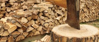
There are different ways to chop wood. Traditionally, it is customary to strike with an ax, trying to split a sawn fragment of a log, striking the end part.
A heavy wedge (the ax is wedge-shaped) is inserted into the body of the log. If you come across wood without knots and with a loose structure, then even with relatively little physical effort, the wedge will be inserted inside. Tangential forces will push the fibers apart, causing the body to split into two components.
If the apex angle is made small, then the wedge-shaped body will penetrate deeply inside, but the magnitude of the tangential forces will be small. The destructive force will not be enough. The ax will jam in the resulting gap.
When a less acute angle is formed, the tangential forces will be more significant. They can split wood.
With slow penetration of the wedge, the kinetic energy not accumulated as a result of the swing and subsequent impact becomes decisive. The process occurs by introduction into a plastic body, where, when certain values are reached, the bonds between the fibers are broken.
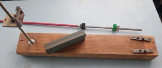
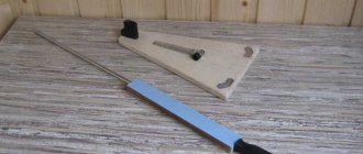
Assembly diagram of a hand-held device
This type only makes the process of splitting logs easier, so you still have to work hard.
For production we will need:
- materials that you already have, or you will have to purchase them;
- drawings, video tutorials from practitioners, photos of finished copies and the work process - finding these materials on the Internet is not so difficult;
- tools - grinder, welding inverter;
- welder skills, the ability to draw up and calculate a diagram and ingenuity, because any ready-made diagram will need to be adapted to the parts you have on hand.
A round frame is brewed, the diameter of which is slightly larger than the diameter of the chocks (approximately 23 cm). To do this, you need to take a round, thick metal blank and weld two pipes to it, the height of which should be 35 cm. To complete the frame, you will also need to weld a ring on top. A knife is installed at the bottom with the tip facing up, and holes for fasteners are made in the base.
A log is placed on the knife and hit with a sledgehammer on top. However, it is worth remembering that such a wood splitter is only suitable for soft wood species.
Types of mechanical cleavers for firewood: their advantages and functional features
There are many more types of mechanical wood splitters than manual ones. This is due to the wide variety of types of drives used. However, the advantage of mechanical devices lies not only in the virtual absence of physical effort, but also in the ability to split large-sized firewood. Split firewood is much easier to cut into small logs than to cut large logs.
The operating principle of mechanical wood splitters is based on the following manipulations:
- laying or installing logs in a special chute;
- the drive (there are different types) drives the supporting part or cutting blade, thereby influencing the workpiece;
- the knife digs into the wood, as a result of which the workpiece splits into two or more parts, which also depends on the design of the knife.
The undeniable advantage of such units is also their high speed of operation, as well as the ability to process large volumes of firewood. It should be noted that thanks to mechanical wood splitters, it is possible to split wood of various species, which manual devices cannot always cope with.
Like manual wood splitters, mechanical devices can also be made by yourself. Moreover, you don’t need to buy anything for this, since the devices can be made from improvised materials that are available in your garage. Actually, we will pay special attention to this, but first we will consider what types of mechanical devices are divided, and how they differ.
Making a spring log splitter
You will need:
- channel section;
- corners;
- car spring;
- knife plate;
- pipe section;
- hinge joint;
- weighted rail.
First, we prepare a support for the future wood splitter and prepare a platform for the spring. The next step is to weld the pipe, spacers and platform to the support. We cut out a place for attaching the beam to the support. We hang the beam itself with the hinge unit on the support and weld it, maintaining its mobility. We attach the beam with the cleaver in a horizontal position. We weld the rail and handle to our wood chopping machine.
Lowering onto the block, the cleaver splits it and returns to its original position - that’s the whole principle of operation.
About the design
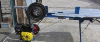
Basic design of a cone log splitter
The machine consists of two main parts:
- The base part is represented by a strong frame. It is made from a profile pipe and has the shape of a bedside table. Consists of four racks connected to each other by jumpers. The top is covered with a steel sheet to the size of the perimeter and a thickness of 10 mm. Two bearing mounts are installed on it. A similar plate is attached at the middle level. Holes are drilled in it to mount the electric motor. A table for feeding material is welded to the frame. It is made from two racks, using a profile pipe, connected by a jumper. The top is made of steel sheet. The dimensions correspond to the perimeter of the table. Metal thickness 10 mm. A knife is welded to the surface of the table to separate the log. It prevents a fragment from unexpectedly falling under the screw cone with its subsequent tightening and deformation of the shaft. It is welded strictly under the cone at a distance of 20 mm from the largest diameter of the cone included in the kit for this machine.
- The mechanical part is represented by a shaft, two bearings, a pulley that reduces the speed of rotation, a cone with a screw thread, an electric motor, a small pulley for the engine and a rubberized belt.
How does it work?
The steel shaft is placed in bearings and installed in mounts on the frame. A pulley with a diameter of 400 mm is attached to its end. An electric motor with a small pulley with a diameter of 140 mm is installed on the middle platform. A belt drive is installed between them.
The difference in pulley diameters makes it possible to reduce the rotation speed from the engine to the shaft with a cone by three times, but allows you to increase the power of the machine by 3 times.
The length of the cone is 250 mm, the diameter of the base for the shaft ranges from 40 mm to 100 mm.
A hole for the shaft is drilled in the base. The cone is secured to the shaft using screws or internal threads.
Types of drives for cone splitter
The drive for producing the work of a mechanical cleaver can be:
- Electric motors powered from a mains voltage of 220 V and 380 V. The choice depends on the required power of the machine.
- Internal combustion engines running on gasoline or diesel fuel.
- From a special device on a mechanical lawn mower or mini tractor. This is a temporary drive.
Operating principle of an electric cleaver
The material is in a vertical position. The principle of manual feeding is necessary for tactile control of the pressure on the block. The cone is screwed into the wood using a screw thread. The shape of the cleaver ensures gradual splitting of the tree into logs of the required size. All that remains is to put the resulting product in the woodpile.
Important! Particular attention must be paid to the safety of work on these machines. They have a large number of exposed rotating parts with high power. Electric current is used to operate. It is important to follow all safety regulations
Mandatory use of protective clothing and personal protective equipment, mittens, tarpaulin boots, glasses
It is important to follow all safety regulations. Mandatory use of protective clothing and personal protective equipment, mittens, tarpaulin boots, glasses
Screw (cone-shaped) machine
A common model for harvesting firewood in small volumes is a machine with a conical cleaver, which can be additionally threaded, and is driven by an electric or gasoline engine. Such a device splits lumps due to a rotating cone, tearing the wood, and mechanical pressure exerted on the workpiece by a person.
You can buy the cutting part or grind it yourself if you have lathe skills. Remember that the presence of a thread will make it easier for you to work with a wood splitter, so it is advisable to cut it (we recommend left-hand cutting). Thread depth 2−3 mm, pitch 6−7 mm. The nose of the cone should be sharp. The landing site on the gearbox must have a depth of at least 70 mm.
The engine must have a power of 1.5-2 kW, voltage - from 380 V. The number of revolutions is 250-500 per minute, the speed below 250 rpm will greatly slow down the process of collecting firewood, and above 500 rpm there is a danger of the logs being pulled out of your hands . If you have an engine with a given number of revolutions, you can put a “carrot” on the crankshaft. If the revolutions go off scale, you will have to install a reduction gearbox or make a belt or chain drive to reduce the rotation speed.
The bed is the table on which the logs will be placed. It is made either from sheet steel or from thick wooden boards; the legs for it must be metal 40 cm long.
The distance from the table to the cleaver is 8-20 cm; if you increase it, there is a danger of turning over small-diameter logs. Installation of the log is vertical, otherwise the tree will get stuck between the “carrot” and the table and, most likely, bend the shaft. The workpieces should be no longer than 0.5 m and not exceed a diameter of 0.6 m. For this wood splitter, do not take tree species with intertwined fibers (birch, oak, etc.). For safe operation, place the cover over the motor and chain (belt).
Other nuances
The gear ratio of the gear unit is of great importance . It is determined using information about the number of turns of the electric motor and the required torsion parameters of the output shafts. The indicator established as a result of the calculation is rounded to the nearest standard value. It is important to note that the motor shaft, and therefore the output gear shaft, should not rotate faster than 1500 times per minute. Within these limits, the motor parameters are selected according to the general requirements for the device.
The required number of steps is established according to special tables. The initial indicator for determination is precisely the gear ratio. If GOST for a gearbox states that it will be used “occasionally,” this means that :
- the maximum load will be 2 hours for every 24 hours (no more);
- 3 or 4 starts per hour (no more);
- mechanical movements are carried out without striking the mechanism itself.
The so-called cantilever loads on the shafts are also determined. They must match the level specified in the accompanying documents for gear units, or even be less. It is necessary to take into account both the average level of work over an hour (in minutes) and the torque. Since all these nuances are difficult to predict in home-made designs, it is not recommended to make gearboxes from the rear axle and similar auxiliary units . The quality of their work turns out to be unsatisfactory compared to even “average” factory devices.
A geared motor is preferable if compactness of the drive is a priority. Over 95% of structures of this kind are designed for arbitrary placement of the output shaft. The step-by-step assembly instructions also note that there is no need to use couplings when connecting the motor and gear assembly. But you need to understand that such devices are expensive. In addition, an individual order with the required parameters must be sent each time.
By independently assembling an analogue that requires the use of couplings, you can easily reduce costs by 10% or even 20%.
Hand-assembled hydraulic wood splitter
If the amount of firewood to be harvested is very large, it is worth considering the construction of a more complex unit for processing it. A hydraulic wood splitter is more difficult to make, but quite possible. Here is the principle of its operation: the block, under the pressure of the cylinder, slides along the platform to the knives, where it splits into pieces. Depending on the design features of the knife, the chock can be divided into 2, 4, 6, 8 parts.
When assembling a wood splitter, you need to consider the following parameters:
- horizontal or vertical arrangement of the block;
- the largest size of chocks prepared using the mechanism;
- the splitting force of the log, which depends directly on the size of the hydraulic cylinder and engine power.
You will need a hydraulic cylinder, an oil tank, pumping equipment, a fluid flow control unit, a control unit, and an engine.
First you will need to make a frame; if in the future you are going to move to another place for collecting firewood, think in advance about a wheeled version of the wood splitter. Attach part of the assembly with hydraulics to the frame. To connect these elements into a working chain, it is better to invite a good hydraulics specialist.
The design can be more simplified: the cross-shaped knife is replaced by a cleaver, and the hydraulic cylinder is replaced by a jack, respectively. If you used a jack as a driving element, then remember that pressure is created in it only on one side of the piston, and the return stroke is provided by springs. In a hydraulic cylinder, oil can create pressure from different directions due to the supply of oil behind or in front of the cylinder. This significantly speeds up travel in the opposite direction.
About types of systems and more
When preparing to assemble a mechanical or hydraulic wood splitter, you need to start by preparing kinematic diagrams. They will show you what types of gear units should be used.
- In a horizontal cylindrical apparatus, the axes of the input and output shafts are located in a common plane, but on parallel lines.
- Vertical gearboxes are similar in structure - only the orientation of the main plane differs.
- In single-stage worm gearboxes, Two-stage worm gearboxes are designed with shaft axes placed parallel to each other. They are deliberately placed in different horizontal planes.
- Bevel-helical gearboxes are also a special type . Among the two shafts, the output has increased importance. It is its orientation in space that has a decisive influence. In worm-type devices, one type of gearbox can be installed for all orientations of the output shaft in space. The cylindrical and conical designs almost always allow the output shafts to be positioned strictly horizontally. Exceptions are rare; for the most part they are achieved through design tricks.
With the same dimensions and weight, cylindrical mechanisms are 50-100% more efficient than their worm-type counterparts. They last just as long. That is why (for reasons of economic efficiency) the choice is completely obvious.
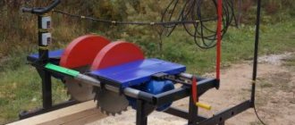
Rack and pinion version of the device
The basis of such a unit is a pusher mounted on a rack, moving due to a gear transmission. The mechanism is activated by pressing a special handle that engages the gears. The pusher moves the log onto a fixed knife and the latter divides the workpiece into parts. Pulling the handle back returns the pusher to its original position. The movement is provided by a motor, which transmits torque to the gear using a V-belt drive.
Basically, when assembling a wood splitter, you have to adjust the stroke of the rack. Safety is ensured by a smooth increase in power in the belt drive. When overloaded, the belt slips, preventing engine damage.
The wood splitter consists of a motor drive, a belt drive pulley on the output shaft, a counter pulley, larger in diameter, rotating on bearings on the secondary shaft, a gear on the secondary shaft, a spring-loaded rack, a frame, a knife, and a control handle.
First, the bed is assembled . The frame for it is made of an I-beam, channel or profile pipe. The pusher mechanism, knife, motor and gearbox are installed. The gear should rise 4-6 cm above the frame and be at a distance of two logs from the knife. A hinge is installed on the carriage, allowing the rack to be raised and lowered, and a spring mount is made, allowing the rack to be raised above the gear. Mount the return spring and install the handle that presses the rack to the gear. If necessary, cut the rail; its length should be less than the distance from the feed plate to the knife.
As you have seen, making a wood splitter is not that difficult if you have working skills. Just carefully study the circuit you have chosen, collect the necessary components, adhere to safety rules during assembly and, finally, pay special attention to the electrical part of your device.
How to choose?
Choosing the right gear unit means guaranteeing the overall reliability of the system and its long-term operation. If you make the slightest mistake, you will have to spend money on repairs or replacement of any part at the most important moment. In the worst case, you will have to change the elements interconnected with the broken part. Therefore, it is very important to use the help of professional designers and engineers.
They pay attention to a variety of factors:
- placement of the gearbox in space;
- its mode of operation;
- general load level;
- the temperature to which the device heats up;
- the type of tasks performed and the degree of their responsibility.
There are many types of gear units. If you choose the right element, the worm gear will work for at least 7 years. The service life of cylindrical systems can be 1.5-2 times longer.
However, obtaining advice from engineers is not always possible in practice. In this case, the simplest recommendations that will be discussed below can help you out.