A surface grinder will be useful for those craftsmen who work with wooden blanks and make furniture.
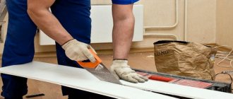
The homemade product is intended for sanding large surfaces made of wood or plywood: it can be a furniture board, a tabletop, etc.
In addition, you can use a homemade device for processing sheet metal blanks.
In this article we will tell you how to make a simple surface grinder from an angle grinder with your own hands.
A little theory: what materials and consumables will be needed?
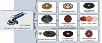
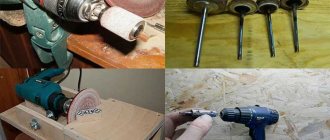
To process workpieces, you can install a Velcro attachment on an angle grinder, to which a round sandpaper of the required grain size, or a flap circle, is attached.
The body of a homemade surface grinder can be made of plywood or MDF. To fasten the parts you will need self-tapping screws and PVA glue.
You might also be interested in reading the article: how to make a homemade bench vise from a channel bar and a car handbrake
.
Multifunctional device - miter box
By making the work table for your angle grinder more rotatable, you will get a multifunctional device - a miter box.
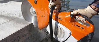
This device allows you to work not only with wood, but also to cut profiles, baseboards, baguettes and other workpieces at a certain angle. To make such a part, you need to install the working disk on the grinder and fix the table at an angle of 45 degrees. It is worth noting that such a unit is considered a real salvation for those who need to cut a large number of window casings, skirting boards and glazing beads. A miter box in combination with an angle grinder allows you to work even with paving slabs in a diagonal direction. And this, in turn, helps to diversify styling options.
Manufacturing the body of a surface grinder
The first step is to make a homemade body. From a piece of plywood or MDF 18-20 mm thick, cut out a blank of the required shape (see photo below).
Using a hand jigsaw or a jigsaw, cut a round hole in the center of the workpiece. It should be slightly larger than the diameter of the petal circle.
After this, using the finished part as a template, it will be necessary to cut out a second such blank. We drill mounting holes in it and screw it to the first part with self-tapping screws.
You need to drill a hole on the side of the body using a feather drill or a wood crown so that you can install the hose of a construction vacuum cleaner.
If you sand large wooden surfaces without using a vacuum cleaner, then the dust in the workshop will rise “above the roof.”
Selecting a feed
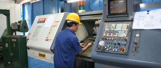
A machine with a tape is more versatile in terms of functionality: it does everything that disk models do, plus much more. Let us immediately note that there are a great many options for amateur models of belt sanding machines.
The fact is that the nature of this machine is very flexible, allowing you to use a variety of available materials, including finds in scrap metal dumps.
The main thing is to know and adhere to three rules:
- The abrasive side of the belt must be adjusted very precisely so that only the workpiece that is being sanded touches it.
- The tape must be evenly tensioned at any time and regardless of the type of work.
- The speed of movement of the machine should be different and should depend only on one thing: the type of part and the nature of the grinding.
How to make a mount for an angle grinder
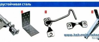
For this we need metal furniture corners and bolts and nuts. In the corners you need to drill holes to match the diameter of the bolts.
Using bolts, two furniture corners are attached to the body of the angle grinder gearbox - it already has threaded holes.
Assembling a homemade device
We install the grinder on the upper part of the body - the petal circle should be inside the body. Then, using self-tapping screws, screw the mounting angles to the body.
We apply sealant around the perimeter of the body, and then glue two plywood boards. Additionally, they must be screwed onto self-tapping screws.
We install the handle of the grinder and insert the hose of a construction vacuum cleaner into the side hole. Our homemade product is ready.
You can watch the video for details on how to make a surface grinder from an angle grinder. This idea belongs to the author of the YouTube channel FACIL LH.
TRUCO PARA TU AMOLADORA ANGULAR FÁCIL – IDEA BRILLANTE
Andrey Vasiliev
Ask a Question
Disc grinding machine
Before starting work, I studied in detail the designs of such machines, looked at articles and videos on this topic. At one time I was thinking about buying it, but decided to make the device myself. I set the following goals: on the one hand, to obtain a machine for grinding small parts made of soft materials (wood, textolite, plywood); on the other hand, learn to develop and design similar products (practical experience in design).
Development stages
I would highlight four stages in my work on this machine:
- Assembly of the first model, prototype.
At the time, I thought I was doing the final version, “the first time.” Everything was drawn by hand and assembled “on the spot”, with adjustments made using a file. The result was ugly, bulky, and inconvenient to use. - Revision and adjustment.
Second model. Based on the initial drawings, based on test operation experience, with design adjustments, the second version of the machine was assembled. It is presented in photographs and described in the current review. - Improvement and modernization.
A useful option has been added: an angle stop. The modification went well, fell into place, and organically connected with the body of the machine itself. - Creating a parametric model of a machine in a CAD program.
In theory, this stage should be the first, but it became the last, since initially there was no understanding and experience in this matter.
Machine characteristics
- weight: 8.5 kg
- overall dimensions (LxWxH): 460x270x240 mm
- motor power: 180 W (50 Hz, 220 V)
- angular velocity (at the edge of the disk) - 14-15 m/s
- reversing the direction of rotation of the grinding disc
- quick change of sanding wheel on the disc
- table tilt angle fixed (90 degrees)
- The possibility of dust removal has been implemented (inlet diameter is 40mm)
Characteristics of the miter gauge
- thrust pad length 120 mm
- adjustment range (scale) ± 60 degrees
"Unfinished construction"
It took me about four years of my life to complete all the stages: the embodiment of ideas and ideas, the finalization (this means calendar years - there were breaks between the stages, external circumstances, other projects, etc.).
When I used to read that personal tech projects could last several years, I was surprised. It seemed to me that why wait so long? I came up with it, drew it, put it all together in a couple of months - the end. But, having worked on a new and complex (for me) project on my own, I begin to understand why exactly this happens: you get distracted by something else, look for a “good” solution, study analogues for a long time, wait for the delivery of components, design everything in detail (at the same time mastering new knowledge and technology), etc.
Sometimes, already during the implementation of the current project, ideas come up for modernization and improvement that are obvious, but do not fit in with the existing design. All in all, welcome to the field of project and product release management.
Design
The general scheme formed in my head quite quickly.
Initially, I did not make drawings (I only ordered an adapter flange for the motor shaft), I assembled and adjusted the parts “on site.” Then (during modifications and upgrades) I looked closely at every detail, its shape, location, size, manufacturing methods, installation and replacement. Not all ideas were realized, but in general the design is functional and suitable for use. The cover over the engine is made removable to give access to the internal space: wiring, capacitors, etc. Rubber feet are provided so that the machine does not “ride” on the table while working. The table is removable, non-adjustable; has a fixed installation angle of 90 degrees (the table can not be tilted relative to the grinding disc).
The power of the existing engine is completely sufficient for hobby needs (even with a small reserve). The harvest on the tree is decent, even if the contact area is large. Of course, if you press the workpiece very hard against the disk, the rotation of the motor will slow down.
Assembly
The assembly was done using glue - this is a quick and reliable way to connect plywood parts. I used PVA glue (water resistance class - D2). The basis of the structure was two 40x50 mm bars, a support platform for the engine and table fasteners were glued to them. A protective-power frame made of plywood 10 mm thick was attached to the top.
Dust removal
Dust removal is available as an option. I tried to eliminate the gaps in the volume under the desktop as much as possible (so that dust could be sucked out more efficiently). Grinding without dust removal is not very good for the health of the worker and the cleanliness of the room. On the side of the case opposite the buttons, under the table, in the case, there is an inlet for connecting the dust removal system. Using a standard 40/32 plumbing adapter, you can connect the hose of a household vacuum cleaner. Tests have shown that with a working dust removal system you can sand even in an apartment. Almost all small sawdust is sucked in, nothing scatters (the main thing is to choose the right direction of rotation of the disk and place the workpiece in the right place).
Sanding disc
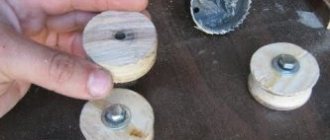
Disc diameter: 200 mm. This size was not chosen by chance; this is the width of standard sandpaper in rolls, which is sold on any market. You can buy a piece of any grain size and cut out the required number of replacement discs. The circle itself is made of plywood. It is screwed to the flange with six M6 bolts. After installation, the circle is turned into place with a chisel (to ensure flatness). The grinding speed (at the edge of the disk) is around 14-15 m/s. which is quite enough for woodworking. The sanding wheel is secured with double-sided tape. I tried changing the sandpaper - it was done easily and quickly, the fastening was strong.
Electrics
No “collective farm” or twisting: all electrical connections are made using terminals, clamps or soldering. A correct reverse circuit for a single-phase motor has been implemented (and not through changing the working and starting windings, as shown in one video on YouTube). Here is a schematic diagram of the electrics and motor connections.
Painting
Regarding painting and putty, I studied the experience of those craftsmen who restore metal machines (but they mostly use epoxy putty).
I didn’t have a utility room to work with - I chose a paint that could be used to paint in a living space and that was safe from an environmental point of view. I settled on water-based acrylic paint. The pigment was selected and mixed separately (the paint was initially white). If I had a workshop, I would now take a more responsible approach to processing and painting the body: I would seal all the cracks and defects of the plywood with putty, sand everything more carefully, and paint it in several layers. If you apply several layers of putty or paint (with intermediate sanding and sealing of all the unevenness and imperfections of the plywood) you will get a very even and smooth surface. With due diligence, you may not even understand what kind of material it is (it will look like plastic, metal).
Angle stop
The last step was making an angular stop for the machine. This is my first stop (which I made and used in my work). Before this I sharpened everything “by eye”, but the result was, to put it mildly, not very good. Working without a stop, jig or guides means getting a mediocre and unpredictable result.
The accuracy of the “scale”, of course, does not reach the factory one, but it allows you to pre-set the angle - and then there is adjustment and more accurate measurements, adjustments. I also recommend moving the axis of rotation of the stop as close as possible to the stop pad. This is not obvious during design, but is clear during operation.
I started making emphasis “from scratch”, not knowing at all what it was and how it would have to be used. At first, there was a lack of understanding of what the length of the thrust pad should be. Therefore, I made two blanks: 100 and 120 mm. I settled on a length of 120 mm. Now I would also provide additional holes for attaching external devices.
Parts for assembling a rough version of the stop, the handle is made from furniture fittings, an aluminum strip (a little wider than necessary) was purchased for the guide. The reason for duplicating the holes was that I couldn’t drill a perpendicular hole the first time (everything was assembled crooked).
We mill a groove for the guide in the machine table. A reinforcing strip of plywood is glued to the bottom. The height of the guide is 6 mm, the depth of the groove is 7 mm, the plywood is 10 mm thick. Initially (in one installation, in one pass of the router) we get a groove of the same width along the entire length of the table. If you make several passes, the groove will be of different widths at the beginning and end (I haven’t figured out how to make it the same width in my conditions, with the tools and skills I have). The guide is shorter in length and can be adjusted to the width of the groove without much difficulty.
Ideally, we will get a smooth movement of the miter gauge (without backlash) along the entire length of the table. In reality, of course, there will be small gaps (due to careless execution, errors and shortcomings of technology, etc.).
Close-up. Numerous flaws in manual marking are visible. In the future, it would be nice to engrave (laser) them directly on the stop or make the scale a separate part and install it on the product.
I tested the miter gauge a little: I tried to grind cubes, and also made a connection at 45 degrees. The cubes did not work out (there was little time and it was necessary to make a device for grinding the edges at 45 degrees (with alignment in three planes)) But the “picture frame” type connection surprisingly turned out to be quite accurate. The planes fit perfectly against each other and form an angle very close to ninety degrees.
Disadvantages, errors:
- the design turned out to be partially non-separable (it is impossible to replace the engine without dismantling part of the housing)
- selected an unsuitable motor with a time limit for continuous operation and rotor imbalance
- Although the grinding disc itself is partially balanced, there are slight vibrations in the machine during operation (due to the motor).
- Now I would redo the electrical circuit of the machine: I would add a large “Stop” button, I would connect the motor not directly, but through a relay (starter). Those. I would make the connection like that of “adult” machines.
Advantages, advantages:
- The dust removal system works very well
- availability of auxiliary devices (angle stop, other additions in the future)
- light weight, compact design dimensions
- low price (if you consider only materials and external work)
Creating a Parametric Model
The last stage of work for me was the creation of a parametric model of the machine in a CAD program.
Drawing in various versions of paper and electronic drawing boards is already a thing of the past. Similar concepts come from the 80s. Now it is much more efficient to model a parameterized solid body and take views and sections from it. This approach is not a replacement for drawings, it is conceptually different. The resulting models can be directly transferred to CAM for production (cutting, milling, 3D printing, etc.).
It was very difficult for me to mentally move from the development concept of “ thought, figured everything out in my head and drew paper/electronic drawings, transferred to production
"to "
thought, created a solid model, corrected errors and inaccuracies, created drawings, transferred them to production
." This took a lot of effort (to change stereotypes), you always want to go the “easy” and familiar path. I remember more than once reading on forums statements from more experienced comrades about which methods of work are most effective, but I passed it by; or could not understand; or understood, but did not have the time and energy to acquire new skills.
For this project I chose FreeCAD. There are quite a lot of lessons and training videos on it. Of course, there are many more complex and professional development packages, but the existing functionality was sufficient for my level and range of tasks. I even managed to set up and launch the rendering (visualization) of the model (although initially I wanted to study Blender 3D for this).
After the stage of getting used to the interface, working with model parameters and assembling all the parts together brings pleasure and allows you to fully concentrate on development, seeing the whole picture as a whole.
I remember how I tried to hold and correlate several interdependent dimensions “in my head” and transfer them to the drawings. And still, after long titanic efforts, I made a mistake and re-ordered the production of individual parts in the assembly.
Conclusions and Conclusion
When practice and theory go side by side, if you have interest and determination, you can master almost any area of human activity and solve a complex complex problem.