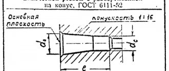
Metric conical threads with a taper of 1:16 are used for conical threaded connections, as well as in connections of external conical threads with internal cylindrical threads with a profile in accordance with GOST 9150-81.
The profile of the internal cylindrical thread connected to the external conical thread must have a flat-cut cavity.
Note.
In the absence of special requirements for density or when using seals to achieve tightness of a threaded connection, the shape of the root of the conical (external and internal) and cylindrical (internal) threads is not regulated.
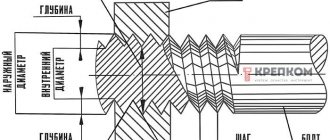
The profile of a metric tapered thread (external and internal) is shown in Fig. 5.
The diameters, pitches, nominal values of the outer, middle and inner diameters of the internal cylindrical thread must correspond to those indicated in Fig. b and in table. 90.
The internal cylindrical thread must ensure screwing in the external conical thread to a depth of at least 0.8l.
The length of the through internal cylindrical thread must be at least 0.8(l1 + l2).
The thread designation must consist of the letters MK (for tapered threads) or M (for internal cylindrical threads), nominal diameter, pitch and standard number (for internal cylindrical threads), for example:
MK20 × 1.5;
M20 × 1.5 GOST 25229-82.
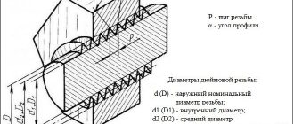
Rice. 5. Tapered thread elements:
d and D are the outer diameters of the external and internal threads, respectively;
d2 and D2 are the average diameters of the external and internal threads, respectively;
d1 and D1 are the internal diameters of the external and internal threads, respectively;
φ—cone angle;
φ/2—slope angle;
P - thread pitch:
H - height of the original triangle
Diameters, steps in the main dimensions of conical (external and internal) threads, mm
l is the working length of the thread; l1 is the length of the external thread from the end to the main plane; l2 - length of internal thread from the end to the main plane
| Thread diameter | R | Thread diameter in the main plane | Thread length | |||||
| 1st row | 2nd row | d = D | d1 = D1 | d2 = D2 | l | l1 | l2 | |
| 6 | — | 1 | 6,000 | 5,350 | 4,917 | 8 | 2,5 | 3 |
| 8 | 8,000 | 7,350 | 6,917 | |||||
| 10 | 10,000 | 9,350 | 8,917 | |||||
| 12 | 1,5 | 12,000 | 11,026 | 10,376 | 11 | 3,5 | 4 | |
| 14 | 14,000 | 13,026 | 12,376 | |||||
| 16 | 16,000 | 15,026 | 14,376 | |||||
| 18 | 18,000 | 17,026 | 16,376 | |||||
| 20 | 20,000 | 19,026 | 18,376 | |||||
| 22 | 22,000 | 21,026 | 20,376 | |||||
| 24 | 24,000 | 23,026 | 22,376 | |||||
| 27 | 2 | 27,000 | 25,701 | 24,835 | 16 | 5 | 6 | |
| 30 | 30,000 | 28,701 | 27,835 | |||||
| 33 | 33,000 | 31,701 | 30,835 | |||||
| 36 | 36,000 | 34,701 | 33.835 | |||||
| 39 | 39,000 | 37,701 | 36,835 | |||||
| 42 | 42,000 | 40,701 | 39.835 | |||||
| 45 | 45.000 | 43.701 | 42.835 | |||||
| 48 | 48,000 | 46,701 | 45,835 | |||||
| 52 | 52,000 | 50,701 | 49,835 | |||||
| 56 | 56,000 | 54,701 | 53,835 | |||||
| 60 | 60,000 | 58,701 | 57,835 | |||||
Rice. 6
For left-hand threads, the letters LH are placed after the conventional designation of the pitch, for example:
MK20 × 1.5LH;
M20 × 1.5LH GOST 25229-82.
The designation of a conical threaded connection corresponds to that adopted for a conical thread.
The connection of an internal cylindrical thread with an external conical thread must be designated by the fraction M/MK, nominal diameter, pitch and standard number, for example:
M/MK20 × 1.5 GOST 25229-82,
M/M20 × 1.5 N GOST 25229-82.
For internal cylindrical threads made in connections with external conical threads, do not indicate the standard number in the designation.
Tolerances
. The axial displacement of the main plane Δl1 of the external and Δl2i of the internal thread (see sketch of Table 91) relative to the nominal location should not exceed the values indicated in Table. 91.
The displacement of the main plane is total, including deviations in the average diameter, pitch, angle of inclination of the side of the profile and cone angle.
The maximum deviations of the cut of the peaks and valleys (dimensions H/8 and H/4), the angle of inclination of the side side of the profile α/2, the thread pitch P and the cone angle φ (the difference in the average diameters over the length l1 + l2) must correspond to those indicated in the table. 92.
The maximum deviations of the internal diameter and cut of the recesses of the internal cylindrical thread (dimensions D1 and H/8) are given in table. 93.
PROFILE
1.1. The nominal profile of the metric tapered thread (external and internal) must correspond to that indicated in the drawing. 1.
The profile of the internal cylindrical thread connected to the external conical thread must have a flat-cut cavity.
Note. In the absence of special requirements for density or when using seals to achieve tightness of a threaded connection, the shape of the cavity of conical (external and internal) and cylindrical (internal) threads is not regulated.
1.2. The dimensions of the profile elements of conical and cylindrical threads are in accordance with GOST 9150-81.
Taper ; ; ;
d
— outer diameter of the external tapered thread;
D
is the outer diameter of the internal tapered thread;
d
2 - average diameter of external tapered thread;
D
2 - average diameter of internal tapered thread;
d
1 - internal diameter of external tapered thread;
D
1 - internal diameter of the internal tapered thread;
- cone angle; — slope angle; P
- thread pitch;
H
- height of the original triangle
Crap. 1
Axial displacement of the main plane Δl1 of the external and Δl2 of the internal thread
Dimensions, mm
In the main plane, the average diameter has a nominal value.
| Nominal thread diameter d | R | Δl1 | Δl2 |
| From 6 to 10 | 1 | ±0,9 | ±1,2 |
| St. 10 to 24 | 1.5 | ±1,1 | ±1,5 |
| » 24 » 60 | 2 | ±1,4 | ±1,8 |
Limit deviations Δl1 and Δl2 do not apply to threads with lengths shorter than those indicated in table. 90.
Scope of application
They are used everywhere - in the automotive industry, machine tool industry, in the manufacture of household appliances and in everyday life. The peculiarity of the technology is that it has firmly entered our lives because of its convenience, and has also captured all areas of production, since structures can be produced both large and miniature. The simplest examples are a nut and a bolt. In the first case, an internal thread was made using a tap, and in the second, an external thread was made using a die.
Nuts and screws of different materials are used everywhere. From the smallest fastenings, for example, when screwing the lid of a mobile phone, to the huge nuts that hold the wheels of heavy-duty vehicles.
Geographically, the method is used all over the world. In Russia there are GOSTs, our markings are measured in mm. Abroad, inch measurements are used. We offer a table showing how millimeters and inches relate:
Diameter in inches
External section in mm
Internal section in mm
How to cut correctly
Threads can be applied to almost any metals and their alloys - steel, copper, aluminum, cast iron, bronze, brass, etc. It is not recommended to do it on hot iron - it is too hard, it will crumble during operation and it will not be possible to achieve high-quality turns, which means the connection will be unreliable.
Tool for the job
Preparation
You need to work on clean metal - remove rust, sand and other contaminants. Then the place where the thread will be applied must be lubricated (except for cast iron and bronze - they must be worked “dry”). There is a special emulsion for lubrication, but if it is not there, you can use soaked soap. You can also use other lubricants:
You can often hear advice to use machine or mineral oil or even lard when cutting threads. They work well, but experts say that it is better not to do this - the chips will stick to the viscous substance, which will lead to rapid wear of the tap or die.
Slicing process
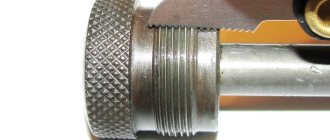
When cutting external threads, the die is placed strictly perpendicular to the surface of the pipe or rod. During operation, it should not wiggle, otherwise the turns will turn out uneven and the connection will be ugly and unreliable. The first turns are especially important. How they “lay down” determines whether the connection will then be skewed.
By applying the internal thread, the part is fixed motionless. If it is a small piece, you can clamp it in a vice. If the plate is large, ensure its immobility using available methods, for example, by fixing it with bars. M
The tap is inserted into the hole so that its axis is parallel to the axis of the hole. With little effort, little by little, they begin to twist in the given direction. As soon as you feel that the resistance has increased, unscrew the tap back and clear it of chips. After cleaning, the process continues.
Photo cutting process
When cutting a thread in a blind hole, its depth should be slightly greater than required - this excess should include the tip of the tap. If this is structurally impossible, the tip of the tap is cut off. At the same time, it is not suitable for further use, but there is no other way out.
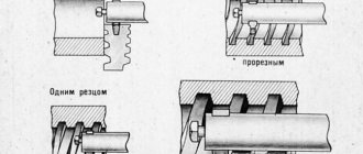
In order for the turns to be of high quality, two taps or dies are used - rough and finishing. The first pass is done as a rough pass, the second as a finishing pass. There are also combined devices for applying threads. They allow you to do everything in one pass.
Another practical tip: to prevent chips from getting into the working area, when cutting, make one full turn clockwise, then half a turn counterclockwise. After this, return the tool to the place where you stopped and make one revolution again. Continue this way until the required length.
Design features
At first, the internal thread was cut using simple devices in the form of a tetrahedral rod sharpened to a cone. At the conical end, cutting teeth were cut out, which, when screwing the rod into the hole, scratched a thread into it. Further improvements resulted in the tap having a positive rake angle, chip ejection flutes, and a better fit of the cutting edges to the thread profile.
A modern tap contains the following mandatory structural elements:
- The head (or intake) part is in the shape of a gentle cone, which serves to begin the formation of the thread profile.
- A certain number (2-6) of lateral grooves that provide chip removal and lubricant (coolant) flow.
- The calibrating part, in the form of an extended cylinder, completes the precise formation of the profile.
- A shank used to secure the tap in the chuck or collar clamping device.
The following types of chip flutes are distinguished:
- Single-radius - the cross-section is an arc of a circle, used on calibration tools.
- Straight - U-shaped cross-section, used for cutting nut threads.
- Mixed - straight front and arched back. This is how most universal tools are made.
Types of tap grooves
In addition, the grooves are divided into:
- Straightforward. Used in a universal tool.
- Left spiral. Left-handed ones are used for cutting threads for passage. The chips are pushed into the space in front of the tap, thus protecting the already formed profile from damage.
- Right spiral. Right-handed taps are used for cutting blind holes; with such grooves, chips are pushed out and do not clog the hole.
The conical shape of the head makes it easier to center the tap in the hole and start cutting the first threads of the thread. The angle of inclination of the cone varies between 3° and 20°, the specific value is determined based on the purpose of the tool - roughing, intermediate or finishing pass.
The cylindrical part is actually an inverse cone with a very small taper angle. The underestimation reaches 0.1 mm, this helps reduce friction during cutting.
Main tap sizes:
- thread pitch;
- profile height;
- full profile height;
- outer thread diameter;
- length of the fence part;
- fence cone angle;
- backing amount.
In addition, the tools are divided into taps with left-hand and right-hand threads.
Types of metric threads
GOST 6211-81 (St Sev 1159-78) basic standards of interchangeability. conical pipe thread
Metric threads are classified according to the following parameters.
- Location of turns. Internal metric threads are found in the holes of parts and products. Taps are used for cutting. External metric threads on rods are obtained using dies.
- Direction of turns. Based on this feature, metric threads are divided into right-handed and left-handed.
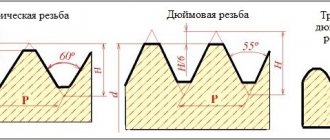
- Step size. The most common are connections with large (standard) pitch. Increasing the number of turns leads to increased reliability. However, the formation of metric threads with fine pitch is possible on workpieces and products made of high-strength materials.
Image No. 5: metric thread with coarse and fine pitch
- Number of visits. Metric threads can be single or multi-start. Increasing the number of visits, if necessary, increases the reliability of connections and solves other production problems.
Features of inch tapered thread
GOST 6211-81. basic norms of interchangeability. conical pipe thread
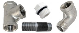
Inch tapered threads have found their application in the industrial sector of Europe and the USA. This type of cutting is used for the manufacture of couplings, elbows, tees, locknuts and other pipe connections. Due to their strength, tapered threads are used in the production of compass gears, screw structures and fasteners for the creation of plumbing fixtures, household appliances and computers, including PCs.
This type of cutting has the following features:
- The tips and turns of inch tapered threads are trimmed or blunted, which provides better tightness;
- the profile angle is constant and equals 55°;
- the conical surface is always at an angle and deviates in a proportion equal to 1:16;
- the maximum cone diameter is 6'';
- the vertices of the thread triangle are always cut or blunted;
- the main cutting parameters (external, internal and average diameters, stroke and pitch) are tabular values.
This type cannot be combined with a cylindrical thread type to create special connections. This is due to different values of the profile angles. If the angle of an inch conical thread is 55°, then the standard cylindrical thread angle is 60°.
This property is due to the conical shape of the helical surface. During tension, the coils are compacted, forming a strong, tight connection and sealing the external cavities of pipes and fastening structures. This feature automatically disappears when the coils are dismantled or recreated.
Most of the parameters of inch tapered threads are indicated in special regulatory reference books, where dimensions and other technical characteristics are recorded in tabular form. The development of all parts and clearances must be carried out within the established values. Otherwise, the structures will not be able to fit tightly together. Mechanisms connected using this type of cutting are easily reconstructed and installed due to the elimination of external defects and deformations of the connections through the tight arrangement of all turns.
Taper thread cutting technology
In the industrial production of npt, threading is performed on a specialized threading machine using a swordsman mounted on a rotating spindle, which automatically forms threads on a stationary pipe.
Design and types of taps
The tap consists of parts:
- shank;
- working part;
- fence element;
- calibration.
Using a shank, the tap is secured in the machine spindle or in a chuck when cutting a threaded connection inside a pipe. The cutting is done by a working part that resembles a screw with spiral grooves. The front part of the tap is often called the fence element, which has the shape of a cone. It is the intake element that begins cutting the thread, then calibration continues. The carving is made by teeth called cutting feathers, which form recesses - grooves through which chips are removed. Sharpening of teeth is subject to technology requirements for cutting parts.
Tap selection
The choice of tap depends on the purpose; they can be hand-held or machine-made. Hand tools are:
- spot;
- uterine;
- nut;
- special.
A die tool is used to pre-cut a threaded connection in one pass. Cleaning of chips is carried out with a mother device with grooves in the right direction.
Grooveless devices are more durable, and the length of the screwed part makes it possible to reconfigure the tool repeatedly. The advantage of grooveless taps is their high productivity and versatility - they can process pipes and blind joints.
By type of work, roughing and finishing taps are distinguished, which are marked according to the size of the thread made by this tool:
- For threads according to the metric standard 8...18 mm, single counters are used.
- In the range of 6…24 mm, a roughing and finishing tap is used.
- Threads 2...52 mm are cut with 3 counters.
Taps have straight and screw versions, right and left, and the cutting part is conical and cylindrical. Conical threads are cut in pipes with through holes, cylindrical ones are used where there are no through passages.
Slicing process
The thread cutting process occurs in stages in several stages:
- Set the direction and speed of spindle rotation.
- The workpiece is fixed in a certain place.
- A tap of a certain standard size is mounted on the spindle, fixing its head with a supporting clamp.
- Turn on the electric drive of the device.
- The threading head is moved to the tubular product by a control lever.
- The workpiece and the thread-cutting tool are fixed and matched with an automatic roller; the machine performs cutting of grooves of the given parameters in automatic mode.
- Having completed the operation, the support with the tap rises automatically, the electric drive is turned off, and the workpiece is dismantled from the machine.
- The accuracy of the geometric parameters is checked and corrections are made if defects are detected.
A conical thread profile is used in cases where communications require complete tightness of the connections of individual pipe elements. The method of tapered threads is invaluable when repairing worn connections on utility pipelines in winter - NPT tapered threads will help restore tightness.
TOLERANCES
3.1. The axial displacement of the main plane of the external and internal threads (Fig. 4) relative to the location should not exceed the values indicated in Table 2.
Damn.4. Axial displacement of the main plane of external and internal threads
Damn.4
Note. In the main plane, the average diameter has a nominal value.
table 2
mm
| Nominal thread diameter | |||
| to 10 | 1 | ±0,9 | ±1,2 |
| » 24 | 1,5 | ±1,1 | ±1,5 |
| » 24 » 60 | 2 | ±1,4 | ±1,8 |
Note. Maximum deviations do not apply to threads with lengths shorter than those indicated in Table 1.
The displacement of the main plane is total, including deviations of the average diameter, pitch, angle of inclination of the side of the profile and cone angle.
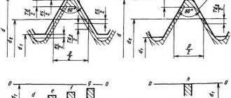
3.2. The maximum deviations of the cut of the peaks and valleys (dimensions and), the angle of inclination of the side of the profile, the thread pitch and the cone angle (the difference in the average diameters along the length) must correspond to those indicated in Fig. 5 and in Table 3.
Damn.5. Limit deviations
Damn.5
Table 3
Dimensions in mm
| Nominal thread diameter | Maximum thread deviations | Difference in average thread diameters over length | |||||||||
| Step on length | Nom. | Prev. off | |||||||||
| external | internal | external | internal | external | internal | ||||||
| to 10 | 1 | +0,032 | ±0,030 | +0,050 | ±0,03 | 0,344 | +0,038 | +0,019 | |||
| +0,015 | -0,019 | -0,038 | |||||||||
| » 24 | 1,5 | +0,048 | ±0,040 | +0,065 | ±0,04 | ±45′ | ±0,04 | ±0,07 | 0,469 | +0,052 | +0,026 |
| +0,020 | -0,026 | -0,052 | |||||||||
| » 24 » 60 | 2 | +0,064 | ±0,050 | +0,085 | ±0,05 | 0,688 | +0,077 | +0,038 | |||
| +0,030 | -0,038 | -0,077 | |||||||||
Note. Maximum deviations are not subject to mandatory control unless specifically stated.
3.3. The tolerance range of the average diameter of the internal cylindrical thread must correspond to 6N according to GOST 16093-81.
3.4. The maximum deviations of the internal diameter and cut of the recesses of the internal cylindrical thread (dimensions and drawing 6) must correspond to those indicated in Table 4.