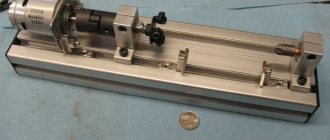
In today's review, the author will share with us his personal experience of making a homemade mini lathe.
The basis of the machine is a square profile pipe 60x60 mm (wall thickness - 3 mm).
The dimensions of the professional pipe were not chosen by chance - it ideally fits a clamping chuck with a diameter of 16 mm. The result is a fairly compact headstock.
If you use a drill chuck with a diameter of 13 mm to make the headstock, then in this case you will need to use a 50x50 mm profile.
We also recommend reading: how to make a simple and compact machine for making clamps for reinforcement cages.
The length of the lathe bed is 22 mm, but if necessary it can be made longer.
Tasks for turning equipment
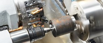
Cylindrical and conical parts are produced using turning. Here the principle of rotation of the part relative to the cutting tool is implemented. In all other types of processing, the workpiece does not move.
When turning, the following operations are performed.
- The cylindrical surface is turned. If necessary, steps are made on it: one or more cylinders of different diameters are placed according to the designer’s ideas.
- They sharpen ledges and grooves for stops or installation of fixing rings or washers.
- Boring internal cylinders or conical surfaces.
- Threads of the required diameter are cut with a certain pitch. It is placed inside or outside the part.
- Using an auxiliary tool, coaxial holes are drilled, countersinks and reamers are used to achieve the required accuracy and cleanliness of processing.
- If necessary, knurling is used to give a special corrugation to the surface or to roll a thread of a special profile.
- Having blanks, thin-walled parts are made from metal or plastic materials using presses using plastic deformation.
- In furniture production, products of complex shapes are often machined; they are called shaped surfaces of rotation. Manufacturing is carried out according to special templates or programs.
Purpose of the equipment
In the technology of processing materials by cutting, it is customary to distinguish processing installations by accuracy classes. The main criterion is the material that needs to be given certain shapes and parameters:
- Wooden blanks are turned on machines that provide accuracy up to 1 mm.
- Structural steel products are sharpened with an accuracy of 0.05 mm.
- On high-precision machines (processing products made of tool steels) equipped with micrometric measuring tools, it is possible to achieve performance up to 0.005 mm.
Woodworking equipment is created for home use, and if it is necessary to work on metal blanks, metal machines are needed. The main differences are in the drive for the tool.
If you need to turn a wooden part, use a stop. The tool is rested on it. Longitudinal and transverse feeding is performed manually.
When processing metal, you have to counteract significant resistance forces. It is quite difficult to hold the cutting edges with your hands. Therefore, auxiliary devices are used that help stabilize the position. Machine tool builders have a concept of AIDS strength.
This abbreviation is deciphered as follows: machine, fixture, tool, part. All these elements must maintain a certain rigidity, then the required accuracy during processing is guaranteed.
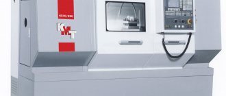
Which motor is better
Assembly drawing of a lathe.
The electric motor is a key part of any metal lathe. The movement of the working part of the apparatus occurs thanks to it and nothing else. The more powerful the motor, the more powerful the machine itself.
The power level of the motor must be calculated depending on the planned work - the size of the metal parts that you are going to work with on your new unit.
If you plan to work with small parts, a motor with a power of about 1 kW will be sufficient. Such motors are found on sewing machines or other household electrical appliances. If your future parts are larger, choose a motor with a power of 1.5 to 2.0 kW.
The power also depends on the material you are going to work with. If, for example, your material is wood, then DIY wood lathes, including a homemade wood lathe cutter, will not require much power.
The most important issue is reliable insulation of all electrical components. The best option would be to consult a specialist. Confidence in the safety of the device and the professional reliability of the design will not hurt you: after all, you are going to work with electricity and metals. And they don't joke with them.
Main nodes
Diagram of a screw-cutting lathe:
The main components and parts of a lathe are:
- All elements are placed on the bed. It is the basis for all equipment. Its strength guarantees the precision of workpiece processing. Industrial designs are cast from malleable or modified cast iron. Then guides are machined along which auxiliary devices can slide. To ensure stability, they try to make this element massive and additionally attach it to a powerful base. Anchors are used to secure the foundation.
- The headstock is equipped with a spindle. A cartridge or drive mechanisms are installed on it. The gearbox is located inside the headstock. If necessary, the chuck rotation speed can be low or high.
- There is also a feed box at the bottom of the headstock. It is needed to organize the movement of the tool.
- The tailstock is installed on the back side of the frame. The most commonly used tool is a quill. It is placed coaxially with the headstock spindle. To process long workpieces, a cone is placed here. It can be stationary or rotating in bearings. You can place drills or threading tools here. A special handwheel allows for longitudinal feed.
- The support is located on the side of the bed. It moves along the guides of the bed. There are devices for fixing cutters installed in a tool holder (a special device for installing several types of tools). The support has auxiliary devices that allow longitudinal and transverse feeding of the tool during processing. By setting the conditions of movement, it is possible to process the surface of parts along a complex profile.
The following are used as auxiliary devices of the machine:
- pump for supplying lubricating coolant (coolant) to the processing zone;
- pallet, chips are collected here, coolant is drained here;
- local illumination helps the turner to direct the lighting to the cutter and the part;
- The protective screen will protect a person from chips, moisture and other dangerous elements.
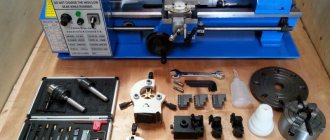
Step-by-step device assembly process
When all the necessary parts have been turned, it is necessary to assemble them into a single structure.
The parts of the future tabletop lathe are assembled on the assembly table.
It was decided to make the structure from flanges machined from round timber with a diameter of 120 mm. To make them easier, a central hole of Ø 55 mm is drilled in them. There are three holes Ø 20 mm.
Additional holes for threaded fasteners are drilled at the end. M6 screws can be used to secure the remaining parts in a given position.
A bronze bushing is pressed in for the future lead screw. Internal Ø 16 mm.
The bed guides are made of ductile cast iron. They have longitudinal grooves. The cylindrical part allows it to be fixed in the flange holes.
The guide is inserted so as to combine all the existing elements.
To maintain a given distance, spacer bushings are used. They are installed in the spacer between the flanges.
The second guide is made exactly the same as the first.
Having assembled the base for the headstock, proceed to assembling the rear one.
The frame is tightened with nuts. The foundation of the future bed has been created.
The machine will stand resting on the front supports. They are secured with screws to the flanges.
Support bushings move along the guides. The caliper and tailstock will be mounted on them. The long sleeve acts as a guide, and the short one acts as a support. The grooves on the rollers do not allow them to move.
Structurally, the support bushings are made of different lengths. This solution allows you to increase the working stroke.
The length of the processed parts can be sufficient so that the parts have dimensions up to 250 mm.
The caliper platform is secured with M6 screws.
The holes for the platform are drilled in place. This part is made individually. If you try to make it only according to the drawing, a jamming effect may appear.
By analogy, the tailstock platform is made. It is also drilled in place. It is necessary to ensure sliding movement along the guides.
It is necessary to ensure the rigidity of the frame. A special cylindrical half ring is machined for the headstock. It is bolted to the flanges.
The movement of tools on the support or tailstock is carried out by a lead screw. A rectangular thread with a slight slope (12.5 ⁰) is machined on it. When the lead screw rotates, the parts attached to it move forward or backward. Depends on the direction of rotation.
A hole with a pressed bushing was created for the lead screw.
To ensure that the screw rotates freely, but does not itself move along its axis, thrust bearings are used. They are placed in front and behind the rear support.
To prevent axial movement of the lead screw, a locking sleeve is installed. It is secured with an M6 bolt. Now the screw will not move along the axis, but it can rotate.
A vernier (a device with notches) is placed on top of the fixing sleeve. One turn of the screw moves the caliper or tailstock 10mm. Using the scale as a guide, precise displacements can be made in the longitudinal direction.
To rotate the lead screw, a handwheel is installed. The small handle allows you to easily rotate the flywheel.
Risk helps you navigate. Looking at it, the desired axial displacement is set.
The machine bed is assembled. Now you need to install the headstock. The part will be recorded in it.
Transverse movement guides are installed on the plates.
The headstock is mounted on top. The picture shows a pulley block, a three-jaw chuck and a central bushing.
The pulleys can be easily removed and installed on the spindle.
The spindle itself is installed inside the central bushing.
There are radial bearings between the spindle and the bushing. They allow free rotation.
The central bushing is bolted to the frame.
After installing the bearings, a spindle with a three-jaw chuck is mounted. A hole Ø 35 mm is machined inside the spindle. If necessary, workpieces of smaller diameter can pass through it.
The machine is ready. The drive is carried out through V-belts from an electric motor installed to the side.
Video: DIY mini lathe.
Safety precautions
Since we are talking about an electrical machine and working with metals, the requirements for compliance with safety regulations will be clear and strict, from which there is no escape. The first step is to check the functionality of the new machine immediately after its manufacture.
How to check the performance of the machine: the spindle should rotate without the slightest difficulty. It is necessary to measure the coincidence of the axis of rotation of the parts in the machine with the center of symmetry of the same part. The common axis should be visible at the front and rear centers.
Elements of the design of a lathe.
The electric motor is always covered with a special casing, which protects the motor from dirt and metal particles, as well as the machine operator himself. If your device is made from a drill, no casing is needed.
If you decide to equip your homemade lathe with a powerful motor, be sure to test on your home network to see if it is enough for your powerful motor. In general, it is better to adhere to established traditions and use old friends - electric motors from household appliances.
Making a homemade metal lathe with your own hands is an excellent and elegant solution from all points of view. Ease of execution, cost savings, efficient processing of parts - all this is about homemade lathes.